World Journal of Mechanics
Vol. 1 No. 3 (2011) , Article ID: 5778 , 18 pages DOI:10.4236/wjm.2011.13019
A Mathematical Model for Magnetohydrodynamic Convection Flow in a Rotating Horizontal Channel with Inclined Magnetic Field, Magnetic Induction and Hall Current Effects
Department of Mathematics, Narajole Raj College, West Bengal, India.
Aerospace Engineering, Department of Engineering and Mathematics, Sheaf Building, Sheffield Hallam University, Sheffield, UK.
Heat Transfer Research, Mechanical Engineering Department, Gonzaga University, Spokane, USA.
E-mail: g_swapan2002@yahoo.com, o.beg@shu.ac.uk, aziz@gonzaga.edu
Received April 8, 2011; revised May 10, 2011; accepted May 20, 2011
Keywords: Hydromagnetic Flow, Hall Current, Electrical Conductance, Free And Forced Convection, Critical Grashof Number, Rotation, Complex Variables, Asymptotic Analysis, Ekman-Hartmann Boundary Layers, Astronautics
ABSTRACT
Closed-form and asymptotic solutions are derived for the steady, fully-developed hydromagnetic free and forced convection flow in a rotating horizontal parallel-plate channel under the action of an inclined magnetic field and constant pressure gradient along the longitudinal axis of the channel. The magnetic field is strong enough to generate Hall current effects and the magnetic Reynolds number of sufficient magnitude that induced magnetic field effects are also present. Secondary flow is present owing to the Hall current effect. The channel plates are also taken to be electrically-conducting. The conservation equations are formulated in an (x, y, z) coordinate system and non-dimensionalized using appropriate transformations. The resulting non-dimensional coupled ordinary differential equations for primary and secondary velocity components and primary and secondary induced magnetic field components and transformed boundary conditions are shown to be controlled by the dimensionless pressure gradient parameter (px), Hartmann number (M2), Grashof number (G), Hall current parameter (m), rotational parameter (K2), magnetic field inclination (q), and the electrical conductance ratios of the upper (f1) and lower (f2) plates. Solutions are derived using the method of complex variables. Asymptotic solutions are also presented for very high rotation parameter and Hartmann number of order equal to unity, for which Ekman-Hartmann boundary layers are identified at the plates. A parametric study of the evolution of velocity and induced magnetic field distributions is undertaken. It is shown that generally increasing Hall current effect (m) serves to accentuate the secondary (cross) flow but oppose the primary flow. An increase in rotational parameter (K2) is also found to counteract primary flow intensity. An elevation in the Grashof number i.e. free convection parameter (G) is shown to aid the secondary induced magnetic field component (Hz); however there is a decrease in magnitudes of the primary induced magnetic field component (Hx) with increasing Grashof number. Increasing inclination of the applied magnetic field (q, is also found to oppose the primary flow (u1) but conversely to strongly assist the secondary flow (w1). Both critical primary (Gcx) and secondary (Gcz) Grashof numbers are shown to be reduced with increasing inclination of the magnetic field (q), increasing Hall parameter (m) and rotational parameter (K2). Applications of the study arise in rotating MHD induction power generators and also astrophysical flows.
1. Introduction
Magnetohydrodynamic (MHD) convection flows constitute a major field of interest in many areas of engineering and the physical sciences. Both translational and rotational flows are of significance in various aspects of astronautical propulsion [1,2], nuclear energy systems [3,4], electro-chemical engineering [5], astrophysics [6], plasma physics [7,8], magneto-lubrication [9,10] and geophysics [11]. Numerous complex phenomena have been addressed for a diverse range of geometries including Hall currents [12], three-dimensional flow [13], wall-conductance effects [14] and impulsive motion [15]. Rotational hydromagnetic flows in particular have attracted considerable attention in the context of MHD energy systems operations and magnetic materials processing. Many techniques have also been employed to render solutions to these boundary-value problems. Takhar et al. [16] obtained numerical solutions for the transient Von Karman swirling magnetohydrodynamic flow from a spinning disk. Bestman and Adjepong [17] studied buoyancyinduced transient compressible rotating MHD convection from a vertical plate with thermal radiation present, using asymptotic methods. Kumari et al. [18] investigated the unsteady vortex magneto-hydrodynamic flow at a stagnation point numerically. Ram and Takhar [19] used a complex variables to study the natural convection rotating hydromagnetic flow from a plate with Hall currents and ionslip effects. Takhar et al. [20] examined Strouhal and Hartmann number and Hall current parameter effects on transient dusty hydromagnetic flow in a rotating channel. Singh et al. [21] obtained exact solutions for rotating HartmannCouette hydromagnetic flow in a parallel plate channel with one of the plates has been set into uniformly accelerated motion. They found that the primary velocity is enhanced with magnetic field i.e. Hartmann number, but reduced with rotation, with the converse response computed for the secondary velocity. Ghosh and Bhattacharjee [22] further studied hydromagnetic convection flows in rotating channels, again presenting closed-form solutions for the effects of rotation parameter and Hartmann number. Asymmetrical wall heating effects on hydromagnetic translational channel flow were considered by Ghosh and Nandi [23]. Vempaty and Satyamurty [24] analyzed the effects of Elsasser magnetic number on hydromagnetic rotating flow in a region bounded by three electrically insulating rigid walls for both antisymmetric and symmetric cases, obtaining analytical solutions for both the transition field regime and strong magnetic field regime. They showed that a separate magnetic boundary layer does not exist, contrary to the case when the rotation vector and applied magnetic field are aligned. They also found that the transition field regime is characterized by the Stewartson double layer boundary layer structure although the outer Stewartson layer is weak and also sub-boundary layers with an axial scale equal to the corresponding boundary layer scale develop at specific locations. Chakraborti et al. [25] studied the rotating hydromagnetic viscous flow and heat transfer past a porous plate rotating with a uniform angular velocity about an axis normal to the plate but with the fluid at infinity rotating with the same angular velocity about a noncoincident parallel axis. They found that a uniform magnetic field applied parallel to the axis of rotation reduces the boundary-layer thickness with an increase in either the plate suction or magnetic parameter, and temperature increases with increasing magnetic field, but decreases with suction. Bég et al. [26] used the implicit Blottner difference method to study hydromagnetic convection boundary layer flow from a spinning sphere with impulsive effects. Further studies using finite element, Laplace transform and network simulation methods on rotating magnetohydrodynamic convection flow have been presented respectively by Naroua et al. [27], Ghosh et al. [28] and Bég et al. [29]. In MHD generator systems the confining walls may exert a considerable role on the flow dynamics and heat transfer processes. Guria et al. [30] therefore analyzed the influence of wall conductance on hydromagnetic channel flows under asymmetric heating boundary conditions. The above studies all considered the applied magnetic field to be either aligned with the flow or transverse to the principal flow direction. However in actual practical systems, the magnetic field may be inclined. Inclination can exert a substantial role on the performance of MHD generator systems. Seth and Ghosh [31] obtained exact solutions for the transient MHD flow in a rotating channel with periodic pressure gradient and a uniform magnetic field inclined with the axis of rotation. They found using asymptotic analysis that for large Hartmann, rotation or oscillation frequency values, the flow is demarcated into two distinct regimes, namely a boundary layer region and a central core region. With large rotation and frequency, flow reversal in the direction of the pressure gradient are generated. Ghosh [32] further studied inclined magnetic field effects on both steady and unsteady hydromagnetic flow with pressure gradient for slowly rotating systems with low frequency of oscillation with low conductivity and weak applied magnetic field. Further studies of magnetic field inclination on hydromagnetic rotating flows were subsequently presented by Ghosh and Bhattacharjee [33] and Pop et al. [34], the latter considering Hall currents. Bég et al. [35] studied the effects of porous drag on rotating MHD flow in a channel under an inclined magnetic field. Bég et al. [36] used the Sparrow-Quack-Boerner local nonsimilarity method to study numerically magnetic Prandtl number effects on two-dimensional, steady forced convection MHD boundary layers, discussing in detail the evolution of the induced magnetic field, temperature and velocity profiles. Ghosh et al. [37] also investigate analytically the magnetohydrodynamic natural convection boundary layer and Rayleigh flow with magnetic induction. In the present study we study the induced magnetic field and velocity distributions in a rotating two-dimensional channel system under an inclined magnetic field with Hall current effects. Using complex variables, exact solutions are derived for the non-dimensionalized flow and magnetic induction equations, subject to prescribed boundary conditions at the plates. We examine in detail the influence of Hartmann number (M2), Grashof number (G), Hall current parameter (m), rotational parameter (K2), magnetic field inclination (q) on primary and secondary velocity and induced magnetic field component distributions. Furthermore we present detailed asymptotic solutions for very high rotation parameter and Hartmann number of order equal to unity, for which Ekman-Hartmann boundary layers are shown to form at the plates. The results are tabulated and presented graphically. We also consider for the first time the variation of the critical Grashof number for both the primary (Gcx) and secondary flow (Gcz) fields. Gcx is minimized with strong rotation and for the case of an applied magnetic field aligned with the positive x-direction (q =p/2). Gcx is also reduced both with a rise in Hall current parameter (m). A similar trend is observed for Gcz which is also shown to be reduced with an increase in inclination, Hall parameter (m) and also rotation (K2). The present study reveals new interesting observations for hydromagnetic phenomena in rotating channels and has thus far not appeared in the scientific literature. The results are relevant to rotating MHD induction energy devices.
2. Mathematical Model
We consider the steady, fully developed magnetohydrodynamic flow of a viscous, incompressible, electrically-conducting Newtonian fluid between parallel plates under the action of a constant pressure gradient, in an (x’, y’, z’) coordinate system. The system rotates with uniform angular velocity, W, about the y’ axis perpendicular to the plane of the flows (x’-z’), in the presence of a uniform magnetic field, H0, which is inclined with the positive direction of the axis of rotation in the x’-y’ plane. The regime is illustrated in Fig. 1 below. Both the fluid and the channel rotate in unison as a rigid body with the same constant angular velocity of rotation. The channel plates are both electrically-conducting with conductivities s1 (upper plate) and s2 (lower plate). The applied magnetic field, Ho, is strong enough to generate Hall current effects, as discussed by Sato [12] and a secondary flow is thereby mobilized in the regime. Magnetic Reynolds number is also of sufficient magnitude that magnetic induction effects become important. Since the plates are infinite along the x and z directions, all physical quantities with the exception of pressure will be functions of the independent variable, y, only. Following Cramer and Pai [38] and Shercliff [39], we take the following vectorial field definitions:
 (1)
(1)
 ;
; 
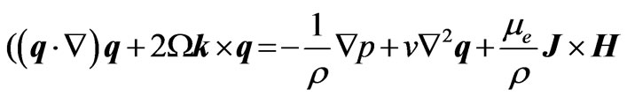
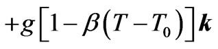
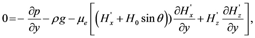
where q, H, E, J are, respectively, the velocity vector, the induced magnetic field vector, the electric field vector and the current density vector. The equations of motion with buoyancy incorporated, for the flow in a rotating frame of reference may be presented as follows:
 (2)
(2)
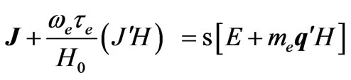
Ohm’s law for a moving conductor incorporating Hall current takes the form:
 (3)
(3)
where  is the fluid density, n is kinematic viscosity,
  is the magnetic permeability,
  is pressure,
  is fluid electrical conductivity,
  is the cyclotron frequency,
  is the electron collision time, b is the coefficient of volume expansion,
  is fluid temperature,
  is the temperature in the reference state,
  is the applied magnetic flux density and
  is the unit vector directed along the y-axis (rotation axis). The equation of continuity (mass conservation),
  , gives
 . The solenoidal relation,
 . The conservation of electric charge (Gauss’s law) gives
 , so that
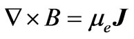
  throughout the fluid regime. The Maxwell electromagnetic equations therefore reduce to the following:
 (4a)
(4a)
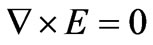 (4b)
(4b)
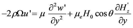
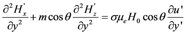
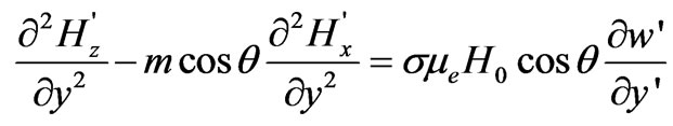
where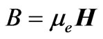 . Under assumptions (1), Equations (2) and (3) may therefore be presented in component form, as:
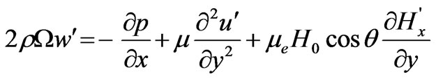 (5)
(5)
 (6)
(6)
 (7)
(7)
 (8)
(8)
 (9)
(9)
Assuming uniform axial temperature variation along the plates of the channel, the temperature of the fluid can be written as:
 (10)
(10)
where N denotes the uniform temperature gradient at the plate and the other terms have been defined earlier. The equation of state is:
 (11)
(11)
Using (10) and (11) and integrating Equation (6) we obtain:
 (12)
(12)
Now using (12), Equation (4) may be written as:
 (13)
(13)
Equations (13), (7), (8) and (9) may further be simplified by casting into non-dimensional form which leads to:
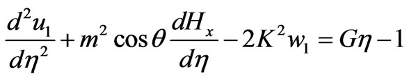 (14)
(14)
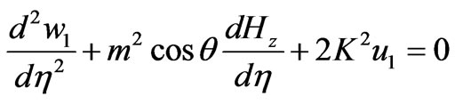 (15)
(15)
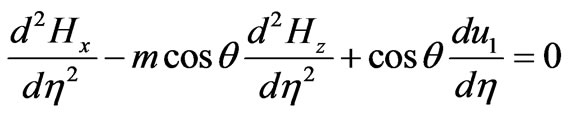 (16)
(16)
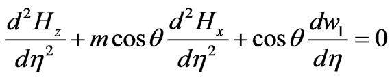 (17)
(17)
where  is the dimensionless distance along the rotational axis,
  is dimensionless primary velocity,
  is dimensionless secondary velocity,
  is dimensionless x-direction (primary) induced magnetic field component,
  is dimensionless z-direction (secondary) induced magnetic field component,
  is the Grashof (free convection) number,
  is the rotation parameter i.e. reciprocal of the Ekman number,
  is the Hartmann hydromagnetic number and
  is the Hall current parameter. The corresponding velocity (no-slip) boundary conditions at the plates are:
 (18)
(18)
The generalized boundary conditions for the induced magnetic field take the form:
 (19a)
(19a)
 (19b)
(19b)
where  and
and  are the dimensionless electrical conductance ratios, L is plate separation, h1 and h2 are the upper and lower plate thicknesses and all other parameters have been defined earlier.
Inspection of (19) indicates that the induced magnetic field depends on the individual values of the conductance ratios,  and
and  Since the plates are electrically conducting, following Mazumder [14], the following condition is satisfied:
 (20)
(20)
3. Complex Variable Solutions
Equations (14) to (17) under conditions (18) and (19(a), (b)) constitutes a two-point ordinary differential equation boundary value problem. The linearity of the equations permits a complex variable solution which is now described. Introducing the complex variables:
 (21a)
(21a)
 (21b)
(21b)
Using (21), Equations (14) to (17) reduce to the following pair of coupled, linear ordinary differential equations:
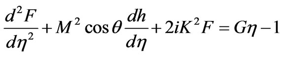 (22)
(22)
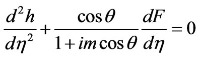 (23)
(23)
The transformed boundary conditions become:
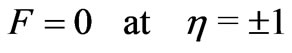 (24)
(24)
The generalized boundary conditions for the induced magnetic field take the form:
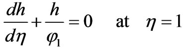 (25a)
(25a)
 (25b)
(25b)
Combining Equations (22) and (23) together with the boundary conditions (24) and (25(a), (b)), the solutions for the velocity and induced magnetic field distributions can be rendered as the following:

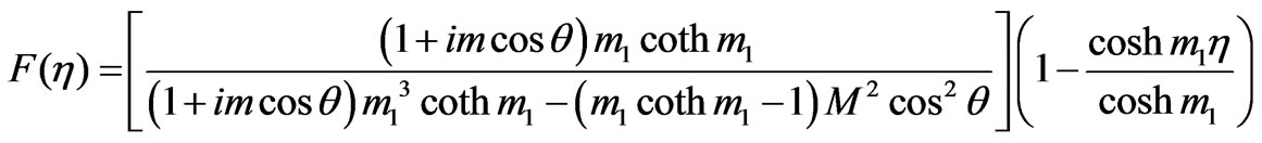 , (26)

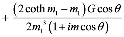

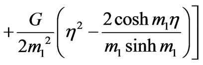 (27)
(27)
The solutions (26) and (27) are valid for nonconducting plates with reference to (20). Equations (22) and (23) can be solved with the help of boundary conditions (24) and (25). This leads to the generation of the following expressions in which ,
,  and
and  are independent of h but are dependent on
  and
and :
:
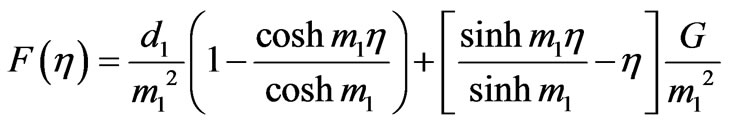 (28)
(28)
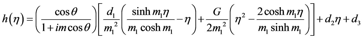 (29)
(29)
where : 
 (30)
(30)
4. Special Cases
I) Forced Convection In the absence of buoyancy forces (G ® 0) the solutions (26) and (27) reduce to the case for pure forced magnetohydrodynamic convection:
 (31)
(31)

 (32)
(32)
I) Forced Convection with a Transverse Magnetic Field With , the applied magnetic field,
  will become orientated along the y-axis i.e. at exactly 90 degrees to the x-z plane of flow. The corresponding solutions will then reduce from (31) and (32) to:
 (33)
(33)
 (34)
(34)
with:
 (35)
(35)
5. Shear Stress Distributions
Let us now consider the important flow quantities from an engineering design point. The shear stress at the upper and lower plates can be derived by taking the first gradient of the velocity function, F, viz.:
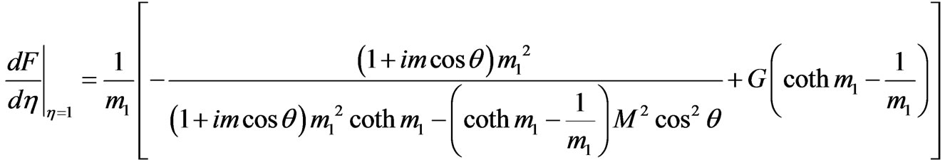 (36)
(36)
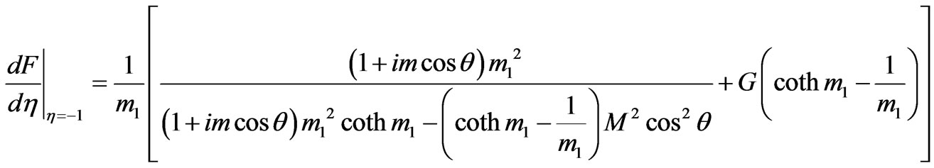 (37)
(37)
From (36) and (37) it is evident that the shear stresses due to the primary and secondary flows vanish neither on the upper plate or the lower plate. There will therefore not be any flow reversal i.e. backflow generated for G = 0 when the plates are assumed non-conducting. These shear stresses are however strongly affected by rotation ( ), Hall current (
 ), and the inclination of the magnetic field (
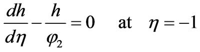
 ). The shear stress due to the primary flow, however, will vanish at the lower plate (h = –1) when the following condition prevails:
 (38)
(38)
Therefore there will be an incipient flow reversal at the lower plate due to the primary flow when:
 (39)
(39)
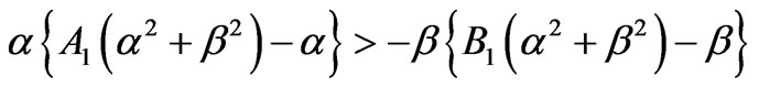
Similarly the shear stress due to the secondary flow will vanish at the lower plate (h = -1) when the following condition is attained:
 (40)
(40)
Equation (40) indicates that flow reversal will arise in the secondary flow due to a decrease in temperature at the lower plate when:
 (41)
(41)
And
 (42)
(42)
Proceeding exactly the same way, the primary flow reversal at the upper plate (h = 1) occurs when:
 (43)
(43)
Similarly the secondary flow reversal arises at the up per plate (h = 1) when:
 (44)
(44)
in which:
 ,
, 
 (45)
(45)
The critical Grashof number given by Equations (43) and (44) will be equivalent to numerically to those given by Equations (38) and (40). We also note that the magnetic boundary conditions (25) for non-conducting walls are in agreement with  at
at . The solutions derived for the velocity and induced magnetic field distributions given in (26) and (27) produce the same results for
  at
at  and
and
 .
.
6. Asymptotic Solutions
We now consider asymptotic solutions. Of course these are restricted to extremely low or high values of certain parameters. We consider here the case for  and M2 ~ O (1). Such conditions will correspond to boundary-layer flow.
  and therefore
  will physically imply very high rotation parameters and correspond to very high Coriolis forces compared with weak viscous forces. M2 ~ O (1) implies weak magnetic field (applied). In the MHD rotating induction motor [8] very rapid rotation will therefore occur i.e. this is extreme end of operating conditions. At the upper plate,
 , using
 , from (26) and (27) we obtain:
 (46)
(46)
 (47)
(47)
 (48)
(48)
 (49)
(49)
where:
 (50a)
(50a)
 (50b)
(50b)
with:
 (51)
(51)
 (52)
(52)
 (53)
(53)
 (54)
(54)
 (55)
(55)
 (56)
(56)
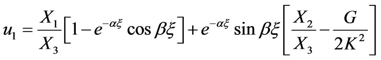
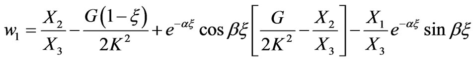
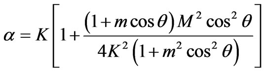
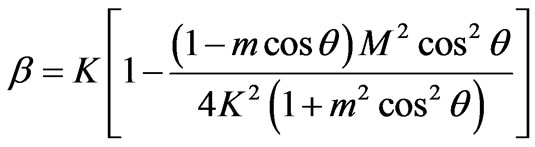
Inspection of expressions (46) to (49) with the inclusion of (50a,b) to (56) reveals that there exists a thin boundary layer of thickness O(a) which we indentify as the Ekman-Hartmann boundary layer. Clearly the boundary layer thickness is dependent on the rotation, Hall current and the inclination angle of the applied magnetic field but independent of the Hartmann number. Conversely the boundary layer thickness is independent of the Hall current and Hartmann number for the case of a longitudinally applied magnetic field for which q= p/2. For this special case the boundary layer thickness will be a function solely of the rotation parameter. The exponential terms in Equations (46) to (49) damp out quickly as x increases when
 . For this scenario we have
 (57)
(57)
 (58)
(58)
 (59)
(59)
 (60)
(60)
Expressions (57) to (60) demonstrate that the primary and secondary flows are affected by Hall current (m), rotation ( ) and Hartmann number (
 ) due to the magnetic field inclination (
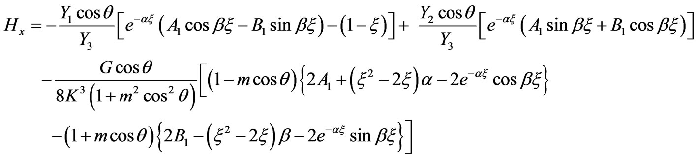
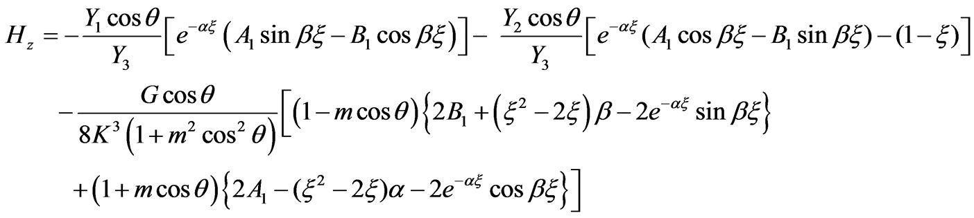
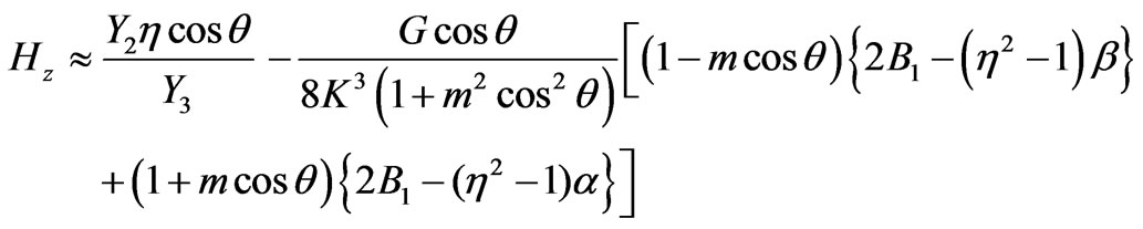
 ); however the secondary flow exhibits buoyancy effects with the variation in the width of the channel (i.e. plate separation). The flow persists in the direction of the longitudinal pressure gradient. The primary and secondary induced magnetic field components, Hx and Hz, as defined by (59) and (60) are clearly affected by the rotation, Hall current, and Hartmann number and depend on channel width. The Grashof number clearly appears as a numerator in both (59) and (60); the coefficient is however negative so that buoyancy force therefore will inhibit magnetic induction. We also note that the induced magnetic field components will change direction while passing through the central section of the channel (
 ) for
) for  (free convection).
  will correspond to cooling of the plates by free convection currents and
  to heating of the plates. Inspection of (57) and (58) shows that while both primary velocity and secondary velocity are influenced by the angle of inclination of the magnetic field, only the latter is affected by buoyancy, via the
  term.
term.
Of course the complex nature of the functions  and
and  necessitates much more detailed analysis to reveal the exact influence of the physical parameters on the magnetofluid dynamic behaviour, which we shall now discuss.
7. Results and Discussion
In Figures 1 to 11 we have presented computations for the variation of primary and secondary velocity components ( ) and primary and secondary induced magnetic field components (
 ) with all key parameters in the model. Figures 2(a) and (b) present the velocity distributions for weak buoyancy (
 ), weak magnetic field (
 ), Hall currents present (
 ) and strong rotation (
 ) with only magnetic field inclination (
 ) varied. It is important to note from the generalized induced magnetic field boundary conditions (25(a), (b)) that three cases can be assessed for the plates. When
 the walls are electrically non-conducting. For
 , the walls are perfectly conducting. For operational conducting walls,
 . We shall principally consider the flow and induced magnetic field characteristics at the centre line of the channel i.e.
 .
.
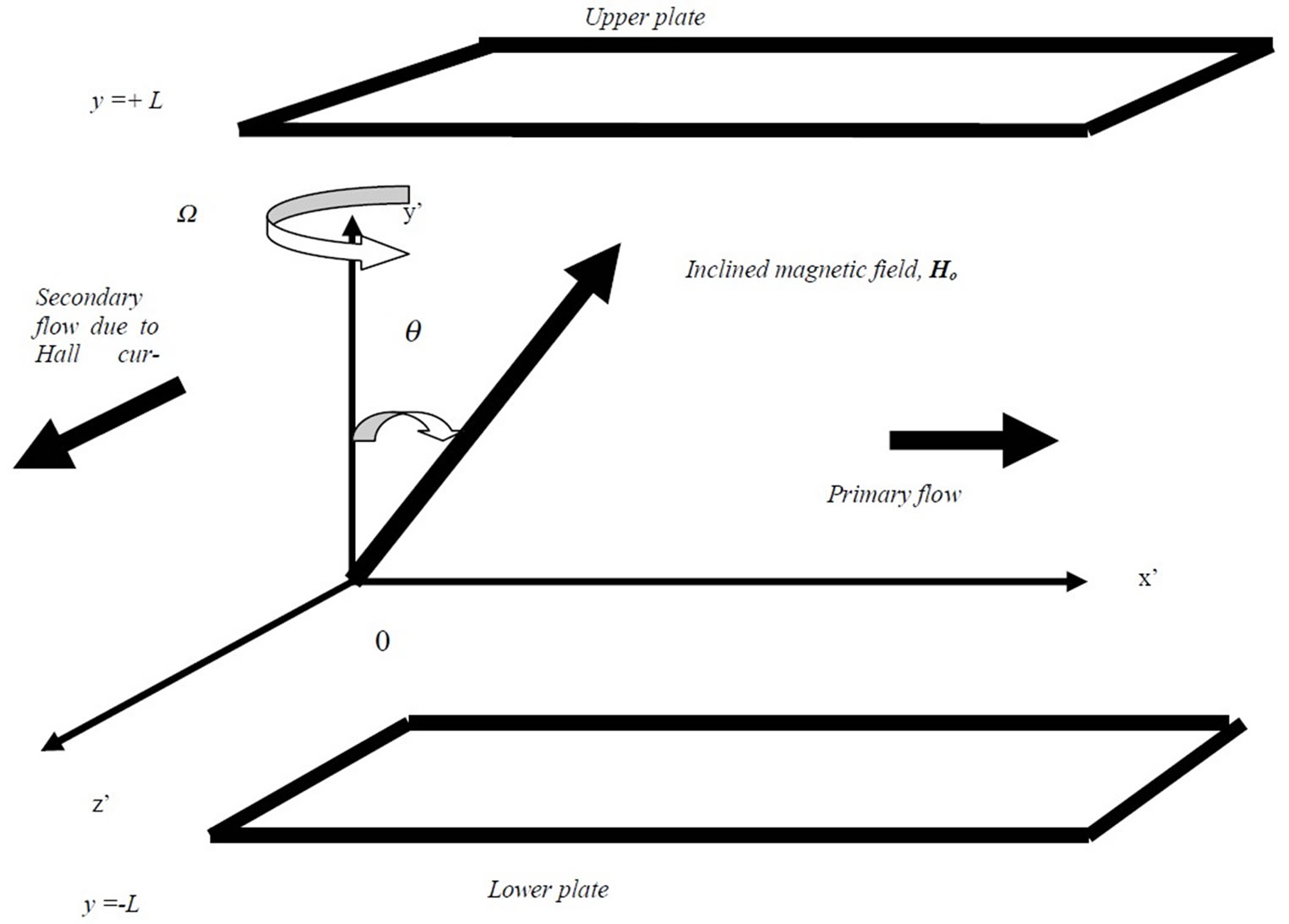
Figure 1. Physical model and coordinate system.
 (a)
(a)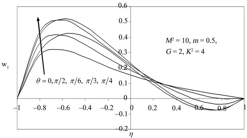 (b)
(b)
Figure 2. Primary (u1) and secondary velocity (w1) distribution for various values of q.
 (a)
(a)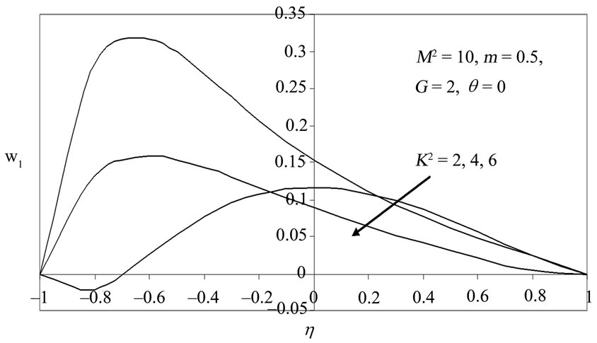 (b)
(b)
Figure 3. Primary (u1) and secondary velocity (w1) distribution for various values of K2 with θ = 0.
 (a)
(a)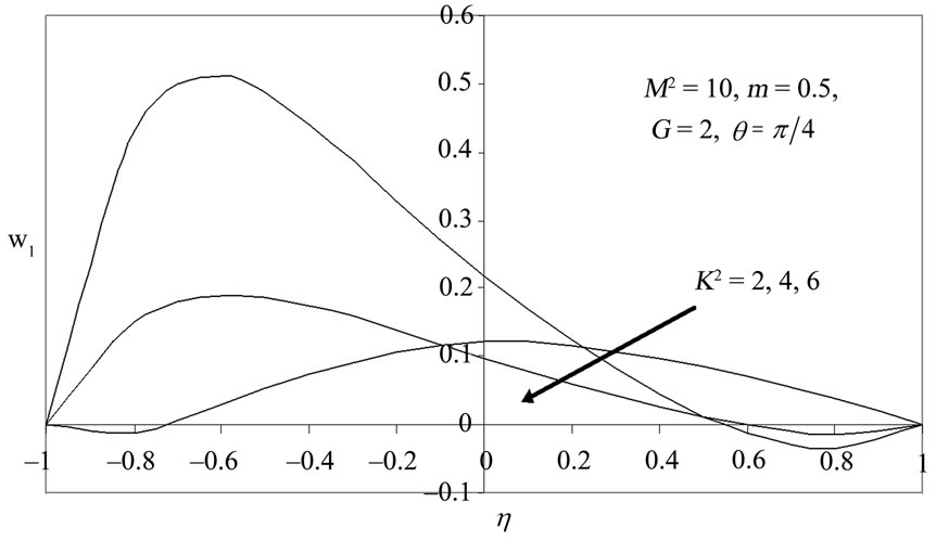 (b)
(b)
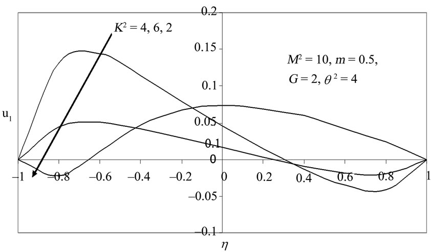
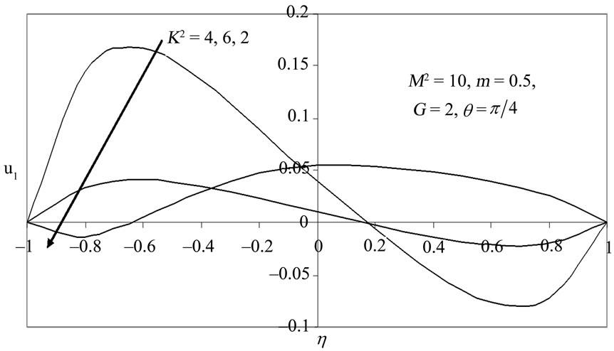
Figure 4. Primary (u1) and secondary velocity (w1) distribution for various values of K2 with θ = π/4.
 (a)
(a)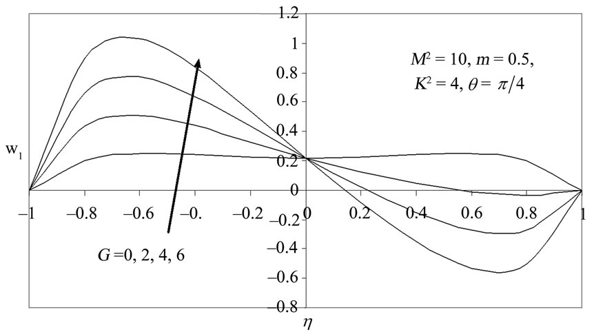 (b)
(b)
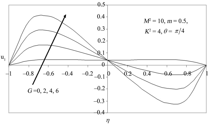
Figure 5. Primary (u1) and secondary velocity (w1) distribution for various values of G.
 (a)
(a)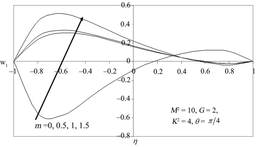 (b)
(b)
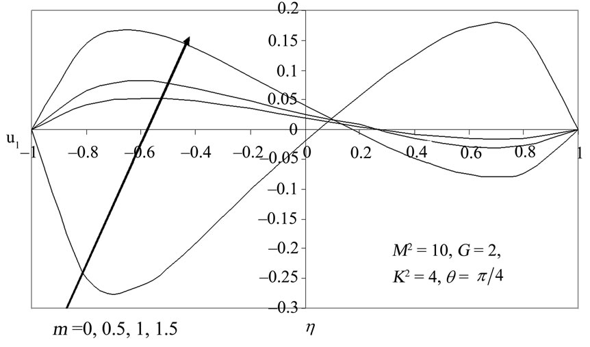
Figure 6. Primary (u1) and secondary velocity (w1) distribution for various values of m.
 (a)
(a)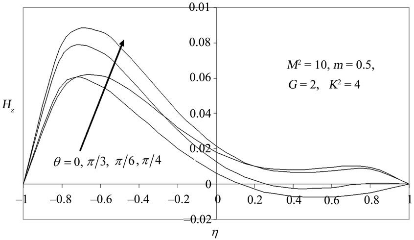 (b)
(b)
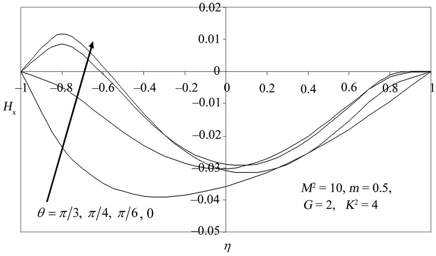
Figure 7. Primary (Hx) and secondary (Hz) induced magnetic field distribution for various values of θ.
 (a)
(a)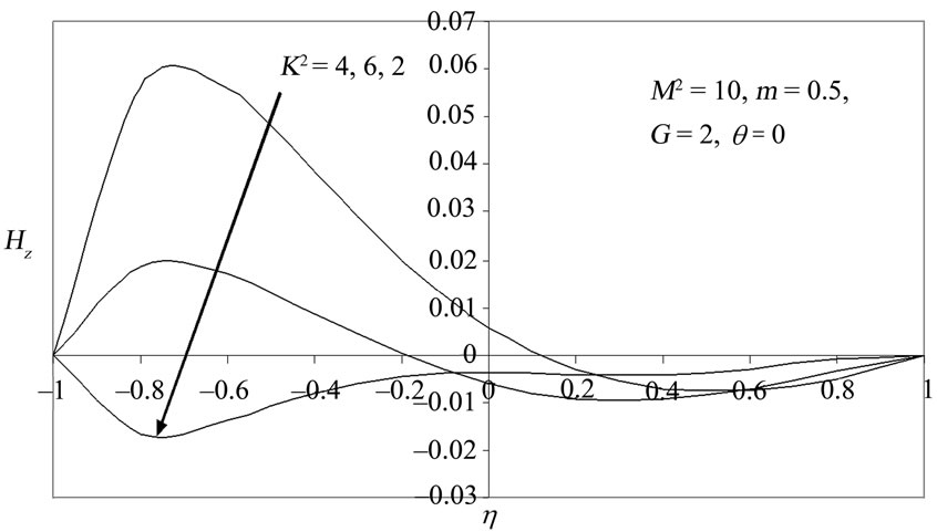 (b)
(b)
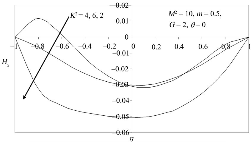
Figure 8. Primary (Hx) and secondary (Hz) induced magnetic field distribution for various values of K2 with θ = 0.
 (a)
(a)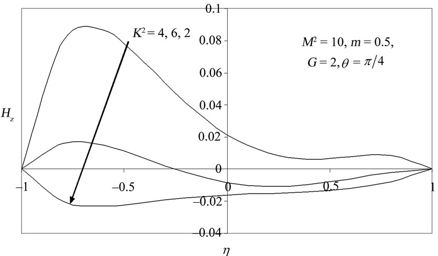 (b)
(b)
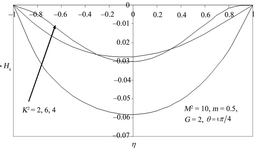
Figure 9. Primary (Hx) and secondary (Hz) induced magnetic field distribution for various values of K2 with θ = π/4.
 (a)
(a)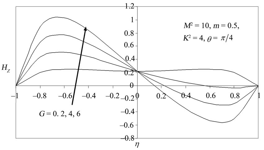 (b)
(b)
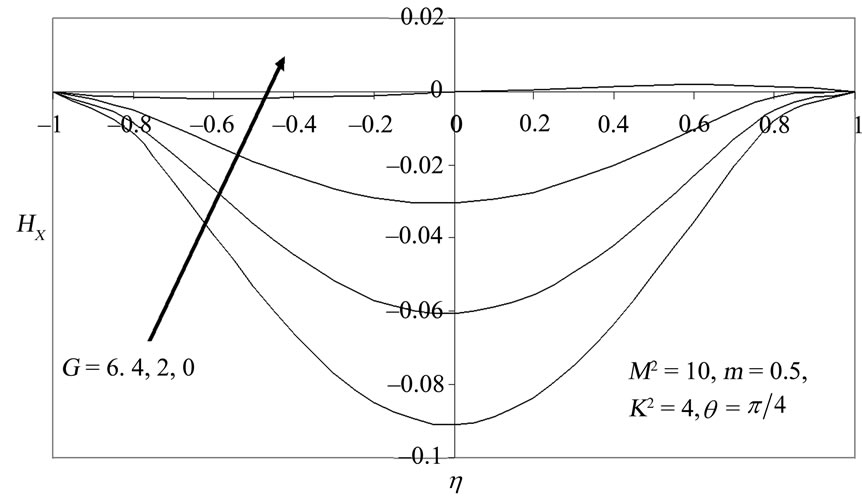
Figure 10. Primary (Hx) and secondary (Hz) induced magnetic field distribution for various values of G.
 (a)
(a)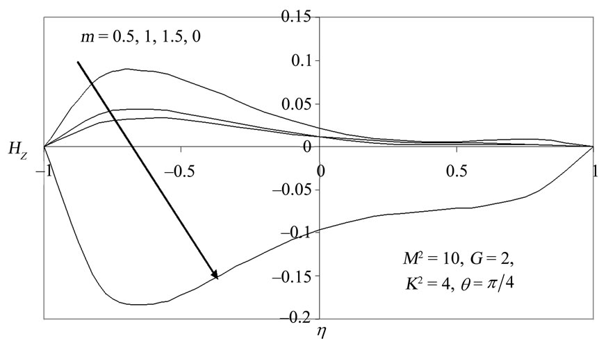 (b)
(b)
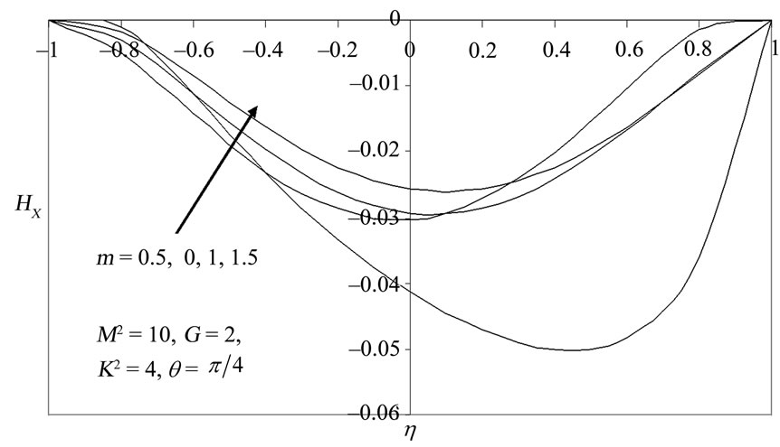
Figure 11. Primary (Hx) and secondary (Hz) induced magnetic field distribution for various values of m.
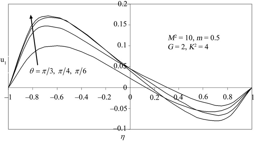
Inspection of Figure 2(a) indicates that primary velocity is generally positive in the lower half of the channel (i.e. for –1 < h <0) and except in close proximity to the channel centre line (h = 0) is negative for the majority of the region in the upper half of the channel (i.e. for 0.2 < h < 1). An increase in inclination, q, from 0 to p/6 (30 degrees to the vertical rotation axis) initially increases primary flow velocity, u1; however with a subsequent increase in inclination to p/4 (45 degrees) and then p/3 (60 degrees), the primary velocity is infact reduced.
In Figure 2(b) a different response is observed for the secondary flow velocity; for the transverse magnetic field case (i.e. the case of a magnetic field aligned with the y-axis, q = 0) the primary velocity in the lower half of the channel is minimized; however only for this scenario is there no backflow throughout the width of the channel (the q = 0 profile remains positive for all h). With an increase in inclination from to p/6 the secondary flow velocity rises at the lower section of the channel and then increases again for q = p/4; however with subsequent increase in inclination to p/3, secondary velocity is reduced a trend sustained with the highest inclination i.e. for the case of the aligned magnetic field (q = p/2). Secondary backflow (i.e. flow reversal) does not occur for q = p/2; however for all other intermediate inclinations flow reversal is caused in upper sections of the upper halfspace of the channel (0.4 < h <1). Therefore we conclude that flow is maximized in the lower halves of the channel section for both primary and secondary distributions; for the former the maximum response is achieved for q = p/6; for the latter it is attained for q = p/4. The worst case i.e. most deceleration of the flow is attained again in the lower channel section for both primary and secondary regimes for q = p/3 and q = 0; the practical implications of these deductions are important in operational conditions of rotating MHD induction devices.
Figures 3(a) and (b) illustrate the velocity component distributions for the case of a transverse applied magnetic field (q = 0) for the effect of various rotation parameters, . The distributions over the same range of
  values, for the case of an inclined applied magnetic field (H0 at 45 degrees to the y-axis) are provided in Figure 4(a) and (b). The primary velocity response (Fig. 3a) is complex in that although the minimal velocity in the lower sections of the channel corresponds to the weakest rotation case (
 = 2) and is infact negative for –1 < h < –0.65, a completely opposite response is observed in the upper channel half space where the velocity is maximum for this value of
 . As such an undulating profile is computed throughout the channel width. An increase in
  to 4 accelerates significantly the primary flow in the lower channel half space (–1 < h <0) which becomes positive throughout this range, peaking in the vicinity of h = –0.7 after which it descends gradually becoming negative (back flow onset) at h ~0.3 and attaining the minimum at h ~0.75. With further increase in
  to 6, the primary flow is however strongly decelerated in the lower channel but less so in the upper channel half space. The parameter,
  , is an inverse Ekman number. It expresses the ratio of Coriolis force to viscous force. Increasing Coriolis force sucks momentum away from the positive longitudinal direction and this is channeled into the negative x-direction (a “tornado effect”) and also spread laterally into the direction normal to the x-axis in the horizontal plane i.e. the z-direction. As a result the secondary flow will be accelerated at the channel centre i.e. h = 0 although only up to a critical point. Inspection of Figure 3b indeed confirms this where we observe that the channel centerline velocity is boosted from 0.12 for
  = 2 to 0.15 for
  = 4; however for
  = 6 the secondary velocity falls to 0.08 at h = 0. For
  > 2 no back flow arises anywhere across the channel. The peak secondary velocity is obtained for
  = 4 at h ~ –0.65; the minimum secondary velocity arises for
  = 2 at h ~ –0.8. As such the results indicate that primary flow can be inhibited in an MHD rotating induction system at the channel centre, with increasing the rotational velocity of operation, whereas secondary flow can be enhanced, although in the latter case, only up to an optimum level after which the further increase in rotational velocity is counter-productive. For the case of inclined magnetic field (q = p/4), Figures 4(a) and (b) we observe that primary velocity, is further reduced at the channel centre with inclination of the applied field. The primary flow is therefore both reduced by increasing rotational velocity, W, and also by inclination of the field, q. Secondary flow (Figure 4(b)) however is further boosted by inclination of the applied magnetic field; values of w1 increase at the channel centre for K2 = 4 from 0.15 approximately to 0.22. Converse to the case for q = 0, there is a backflow induced in the secondary flow with q = p/4, but this is restricted to the lowest part of the channel for K2 = 2 and to the uppermost regions of the channel for K2 = 4 and 6. For the vast majority of the channel width however secondary flow reversal is not instigated.
The effects of the free convection parameter i.e. Grashof number (G) on u1 and w1, again for the inclined applied magnetic field case (H0 at 45 degrees to the y-axis) are presented in Figures 5(a) and (b). The effects of an increase in the free convection parameter on u1 and w1, indicate that an increase in G has no effect on the velocity values at the channel centre which remain fixed at 0.04 and 0.21, respectively. However throughout the channel domain, especially in the vicinity of the plates (h = ± 1) a substantial change in velocities is observed. For the forced convection case (G = 0) velocities are significantly lower in the primary flow throughout the channel width, although backflow never occurs. The profile for this case is a flattened plateau across the channel width. With a rise in G to 2 (free convection), primary velocity is boosted in the lower half of the channel but decreases in the upper half of the channel, leading to significant flow reversal in the latter regime. This trend is maintained with further rise in G to 4 and maximized with the largest value of G = 6. Primary flow is therefore increasingly accelerated in the lower half section of the channel with the cooling of the plates by free convection currents which adds thermal energy to the fluid regime (G > 0); it is consistently decelerated in the upper half region of the channel. Secondary flow is also significantly enhanced in the lower half of the channel with a rise in G from 0 through 2, 4 to 6; reversal does occur in the secondary flow but this is confined to the uppermost section of the channel and is again intensified with an increase in G. Magnitudes of the secondary velocity, w1 are consistently greater for all G compared with the primary velocity. Increasing free convection effects therefore strongly accelerate primary and secondary flows in the lower channel half space but decelerate these velocities in the upper channel half space.
Figures 6(a) and (b) depict the variation of u1 and w1 with the Hall current parameter, m. Without Hall currents (m = 0), backflow is strong in both the primary and secondary velocities in the lower half section of the plate; in the upper half flow reversal is absent for m = 0. An increase in m eliminates the reversal in the primary (u1) and secondary (w1) flow in the lower half of the channel but induces backflow in the upper half of the channel. Both primary and secondary flow are accelerated therefore in the lower channel section (–1.0 < h < 0) but retarded in the upper channel section (0 < h < 1.0). With increasing m, the primary velocity at the channel centre is increased consistently from m = 0 through m = 0.5, to m = 1.0, attaining a maximum of 0.04 for m = 1.5. The peak primary velocity across the channel width however does not arise at the centre but again as in the earlier figures, at h ~ –0.65. A similar trend occurs for the secondary flow velocity at the channel centre, however the magnitudes of velocity are much larger in the lower channel half space for secondary flow since the Hall current effect is strongly associated with secondary flow in magnetohydrodynamics. Conversely the backflow velocities for the primary flow are much greater in the upper channel half space than for the secondary flow. We also note that backflow is initiated closer to the channel centre line for m = 1.5 for primary flow then for the secondary flow.
Figures 7 to 11 illustrate the variation of primary and secondary induced magnetic field components (Hx, Hz) with all key parameters in the model. In Figure 7(a) we observe that the primary induced magnetic field component, Hx is strongly decreased with an increase in the inclination of the applied magnetic field, q. For q = 0, p/6 values are positive only for a short range (–1 < h < –0.6); for q = p/4, p/3, values are always negative. A reversal in the primary magnetic field lines is therefore induced with increasing inclination of magnetic field. This trend is sustained throughout the upper half space of the channel for all values of q. Secondary induced magnetic field component, Hz, (Figure 7(b)) however remains positive in the lower half of the channel (–1.0 < h < 0) for all q and positive for the entire channel width for q = p/3, q = p/4. Hz, is consistently increased with a rise in q. Magnetic field reversal is caused only for q = 0, p/6 in the upper half space of the channel. Peak secondary induced magnetic field component therefore arises for q = p/4 at h ~ –0.7 and the minimal Hz value occurs for q = 0 at h ~ 0.5.
Figures 8(a) and (b) show that an increase in rotation parameter, K2, with q = 0, causes an escalation in primary induced magnetic field component, Hx; for K2 = 2, 6, values are negative throughout the entire channel width; with intermediate K2 (= 6) magnitudes are however positive for a short extent from the lower plate into the lower half space (–1 < h< –0.55). Generally therefore primary magnetic line reversal occurs throughout the channel width except for the intermediate rotation parameter case. Secondary induced magnetic field component, Hz is also reversed for K2 = 2, but for the majority of the lower section of the channel, values become positive for K2 = 4 and K2 = 6. Peak Hx and Hz both correspond therefore to K2 = 4 and attain values of 0.014 (primary) at h ~ –0.8 and 0.06 at h ~ –0.7; once again the secondary positive values are much greater in magnitude than the primary field values. Figures 9(a) and (b) (for q = p/4), indicate that primary induced magnetic field component, Hx; is negative for all K2 values and secondary induced magnetic field component, Hz is negative across the entire channel width only for K2 = 2. The symmetry of primary profiles about the centre line is evident in Figure 9(a). At the centerline Hx values are lowered for the K2 = 4 case from -0.05 (for q = 0, Figure 8(a)) to –0.058 for q = p/4. With K2 = 4, Hz is always positive; for K2 = 6, Hz is negative only towards the centre of the channel and for the entire upper half space region.
Figures 10(a) and (b) indicate that an increase in free convection parameter i.e. Grashof number (G), causes a reversal in the primary induced magnetic field component, Hx; for pure forced convection (G = 0) Hx is positive only in the upper half of the channel and negative in the lower half. For G > 0, the magnitude of Hx is significantly increased but direction reversed. The profiles are symmetrical again about the channel centerline for the free convection cases (G = 6, 4, 2). A markedly different response is shown for the secondary induced magnetic field component, Hz (Figure 10(b)); for pure forced convection (G = 0) secondary induced magnetic field is always positive throughout the channel width. For G > 0, Hz is however completely positive only in the lower channel half space. Flux reversal is produced for G = 6, 4, 2 for h > 0.15, h > 0.21 and h > 0.55, respectively. Effectively free convection currents therefore aid the secondary magnetic induction field (mainly in the lower channel half) but inhibit the primary magnetic induction field throughout the channel.
Finally Figures 11(a) and (b) indicate that the presence of Hall current (m) sustains a decrease in the primary induced magnetic field component, Hx; magnetic line reversal is consistently caused even without Hall current but the effect is amplified in the absence of Hall current (m = 0) for which the least value of Hx (Figure 11(a)) is observed to fall to –0.05 at h = 0.7. On the other hand, secondary induced magnetic field component, Hz is reversed only with Hall current absent (m = 0); for m > 0, values are always positive. Therefore the Hall current assists the secondary magnetic induction but opposes the primary magnetic induction. We note that the Figures 11(a) and (b) correspond to the inclined applied magnetic field case of q = p/4. In Tables 1 to 6 the critical Grashof number as computed in Equations (38) and (40) has been evaluated for various values of the thermophysical parameters for both the primary and secondary flow fields. We note that the critical Grashof number for the primary flow, as defined by
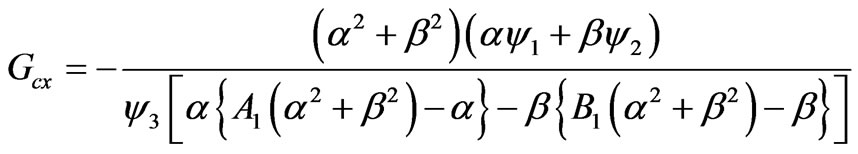
in Equation (38) in the absence of Hall current (m = 0) is observed in Table 1 to be consistently lowered with increasing inclination of the magnetic field, q. With a rise in m, for each inclination angle Table 1 shows that Gcx is progressively also generally decreased, and the trend for variation with q for a given m, also remains the same. There is no effect on Gcx for q = p/2 for any value of m, as discussed earlier. Table 2 shows that Gcx is reduced both with a rise in K2 and also with a rise in m value. Increasing angular velocity of rotation and Hall current therefore reduces the threshold for Gcx. Table 3 indicates that again with increasing rotation parameter, K2, and applied magnetic field (H0) inclination, q, Gcx is gradually lowered. The least value of Gcx therefore corresponds to the case of strong rotation (K2 = 6) and an applied magnetic field aligned with the positive x-direction (q = p/2).
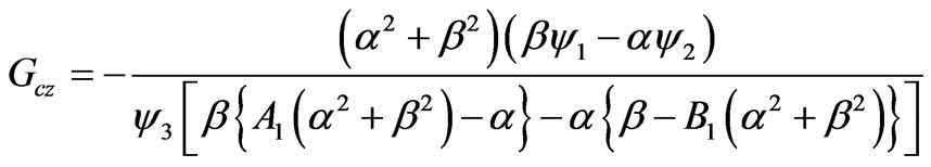
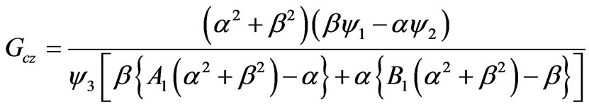
In Tables 4 to 6, the critical Grashof number for the secondary flow, as defined by (40), viz.

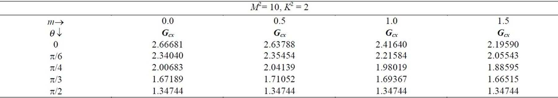
Table 1. Critical Grashof number for primary flow (Gcx) with q and m variation.
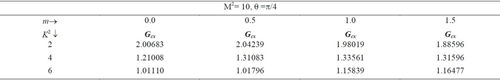
Table 2. Critical Grashof number for primary flow (Gcx) with K2 and m variation.
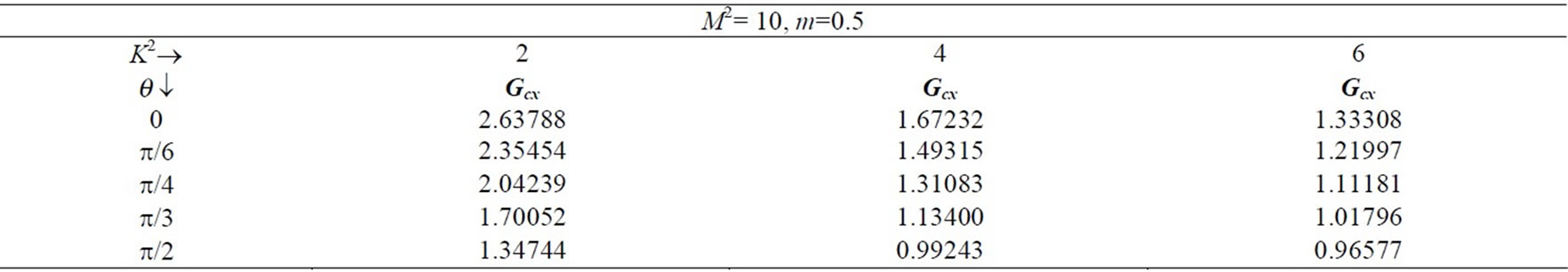
Table 3. Critical Grashof number for primary flow (Gcx) with q and K2 variation.
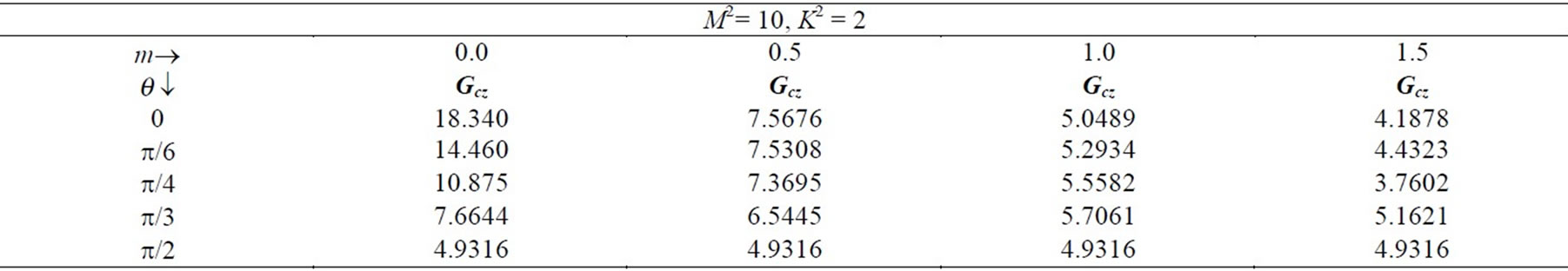
Table 4. Critical Grashof number for secondary flow (Gcz) with q and m variation.
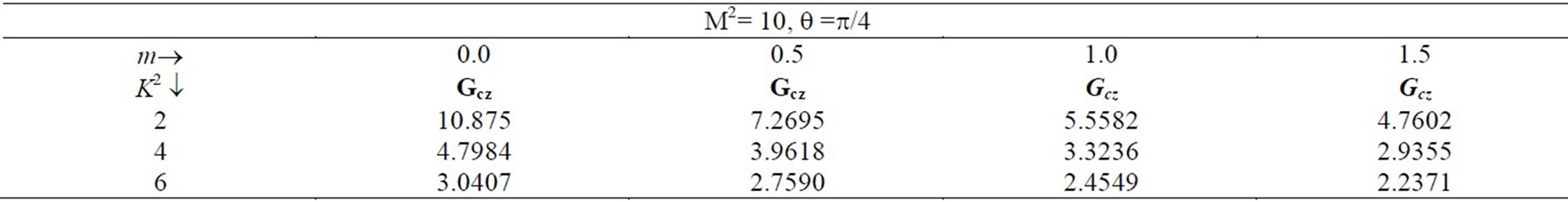
Table 5. Critical Grashof number for secondary flow (Gcz) with K2 and m variation.
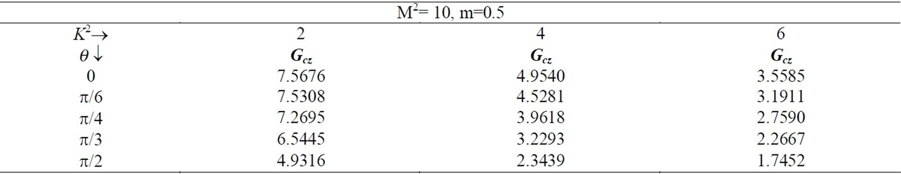
Table 6. Critical Grashof number for secondary flow (Gcz) with q and K2 variation.
at which the shear stress due to the secondary flow will vanish at the lower plate (h = –1), is tabulated for various combinations of q , m and K2. As with the primary flow, an increase in inclination, q for a given m, strongly reduces the value of Gcz. An increase in m also reduces Gcz values for any inclination. Similarly Gcz values reduce also with an increase in m and K2.
8. Conclusions
Asymptotic and complex variable solutions have been derived for the rotating, magneto hydrodynamic free and forced convection flow in a parallel plate channel with Hall currents and inclined magnetic field present. Damping behaviour and critical behaviour have been examined. Our results have indicated that generally Hall currents boost secondary flow and inhibit primary flow; rotation also inhibits primary flow. Increasing Grashof number (free convection) assists the secondary magnetic induction field but opposes development of the primary magnetic induction field. Increasing inclination of the applied magnetic field also serves to inhibit primary flow but aids the secondary flow. The present model finds useful applications in for example hybrid designs for the MHD induction motor. However only Newtonian effects have been examined for steady state flow. Future investigations will extend the current work to consider micropolar [40,41] and viscoelastic [42,43] nonNewtonian fluids and also transient effects [44].
9. Acknowledgements
The authors acknowledge the important comments of the reviewer which have helped to improve the present article.
REFERENCES
- K. Takenouchi, “Transient Magnetohydrodynamic Channel Flow with Axial Symmetry at a Supersonic Speed,” Journal of the Physical Society of Japan, Vol. 54, No. 4, 1985, pp. 1329-1338. doi:10.1143/JPSJ.54.1329
- R. C. Goforth and C. H. Kruger, “Investigation of Secondary Flows in Magneto-Hydrodynamic Channels,” AIAA Journal of Propulsion and Power, Vol. 9, No. 6, 1993, pp. 889-897. doi:10.2514/3.23704
- S. Khan and J. N. Davidson, “Magneyohydrodynamic Coolant Flows in Fusion Reactor Blankets,” Annals Nuclear Energy, Vol. 6, No. 9-10, 1979, pp. 499-515. doi:10.1016/0306-4549(79)90023-9
- H. Kumamaru and Y. Fujiwara, “Magnetohydrodynamic Flow in Rectangular Channel. Effect of Wall Thickness and Interaction of Parallel Channel Flows,” Journal of Nuclear Science Technology, Vol. 36, No. 1, 1999, pp. 110-113. doi:10.3327/jnst.36.110
- Z. P. Aguilar, P. Arumugam and I. Fritsch, “Study of Magnetohydrodynamic Driven Flow through LTCC Channel with Self-Contained Electrodes,” Journal of Electroanalytical Chemistry, Vol. 591, No.2, 2006, pp. 201-209. doi:10.1016/j.jelechem.2006.04.019
- O. Nath, S. N. Ojha and H. S. Takhar, “Self Similar MHD Shock Waves for a Rotating Atmosphere under the Influence of Gravitation,” Astrophysics and Space Science Journal, Vol. 200, No. 1, 1993, pp. 27-34. doi:10.1007/BF00658107
- S. S. Niranjan, V. M. Soundalgekar and H. S. Takhar, “Free Convection Effects on MHD Horizontal Channel Flow with Hall Currents,” IEEE. Transactions on Plasma Science, Vol. 18, No. 2, 1990, pp. 177-183. doi:10.1109/27.131017
- P. C. Ram, A. K. Singh and H. S. Takhar, “Effects of Hall and Ionslip Currents on Convective Flow in a Rotating Fluid with a Wall Temperature Oscillation,” Magnetohydrodynamics and Plasma Research, Vol. 5, No. 1, 1995, pp. 1-16.
- A. S. Slaouti, H. S. Takhar and G. Nath, “Spin-up and Spin-down for a Rotating Disc in the Presence of Buoyancy Force and Magnetic Field and Buoyancy Force,” Acta Mechanica, Vol. 156, 2002, pp. 109-129. doi:10.1007/BF01188745
- J. Zueco and O. Anwar Bég, “Network Numerical Analysis of Hydromagnetic Squeeze Film Flow Dynamics between Two Parallel Rotating Disks with Induced Magnetic Field Effects,” Tribology International, Vol. 43, No. 3, 2010, pp. 532-543. doi:10.1016/j.triboint.2009.09.002
- D. E. Loper, “A Linear Theory of Rotating, Thermally Stratified, Hydromagnetic Flow,” Journal of Fluid Mechanics, Vol. 72, No. 1, 1975, pp. 1-16. doi:10.1017/S002211207500290X
- H. Sato, “The Hall Effect in the Viscous Flow of Ionized Gas between Parallel Plates under Transverse Magnetic Field,” Journal of the Physical Society of Japan, Vol. 16, No. 7, 1961, pp. 1427-1433. doi:10.1143/JPSJ.16.1427
- B. C. Chandrasekhara and N.Rudraiah, “Three Dimensional Magnetohydrodynamic Flow between Two Porous Disks,” Applied Scientific Research, Vol. 25, No. 1, 1972, pp. 179-192. doi:10.1007/BF00382294
- B. S. Mazumder, “Effect of Wall Conductances on Hydromagnetic Flow and Heat Transfer in a Rotating Channel,” Acta Mechanica, Vol. 28, No. 1-4, 1977, pp. 85-99. doi:10.1007/BF01208791
- H. S. Takhar and G. Nath, “Unsteady Flow over a Stretching Surface with a Magnetic Field in a Rotating Fluid,” Zeitschrift fur Angewwandte Mathematik und Physik, Vol. 49, No. 6, 1998, pp. 989-1001. doi:10.1007/s000330050135
- H. S. Takhar, A. K. Singh and G. Nath, “Unsteady MHD Flow and Heat Transfer on a Rotating Disk in an Ambient Fluid,” International Journal of Thermal Sciences, Vol. 41, No. 2, 2002, pp. 147-155. doi:10.1016/S1290-0729(01)01292-3
- A. R. Bestman and S. K. Adjepong, “Unsteady Hydromagnetic Free-Convection Flow with Radiative Heat Transfer in a Rotating Fluid: II—Compressible Optically Thin Fluid,” Astrophysics and Space Science Journal, Vol. 143, No. 2, 1988, pp. 217-224. doi:10.1007/BF00637135
- M. Kumari, H. S. Takhar and G. Nath, “Vorticity Interaction in a Two-Dimensional Unsteady Stagnation Point Flow with an Applied Magnetic Field,” Mechanics Research Communications, Vol. 18, 1991, pp. 151-156. doi:10.1016/0093-6413(91)90061-Z
- P. C. Ram and H. S. Takhar, “MHD Free Convection from an Infinite Vertical Plate in a Rotating Fluid with Hall and Ionslip Currents,” Fluid Dynamics Research, Vol. 11, No. 3, 1993, pp. 99-105. doi:10.1016/0169-5983(93)90009-Y
- H. S. Takhar, P. C. Ram and S. S. Singh, “Unsteady MHD Flow of a Dusty Viscous Liquid in a Rotating Channel with Hall Currents,” International Journal of Energy Research, Vol. 17, No. 1, 1993, pp. 69-74. doi:10.1002/er.4440170109
- A. K. Singh, N. C. Sacheti and P. Chandran, “Transient Effects on Magneto-Hydrodynamic Couette Flow with Rotation: Accelerated Motion,” International Journal of Engineering Science, Vol. 32, No. 1, 1994, pp. 133-139. doi:10.1016/0020-7225(94)90155-4
- S. K. Ghosh and P. K. Bhattacharjee, “Magnetohydrodynamic Convection Flow in a Rotating Channel,” Archives of Mechanics, Vol. 52, No. 2, 2000, pp. 303-318.
- S. K. Ghosh and D. K. Nandi, “Magnetohydrodynamic Fully Developed Combined Convection Flow between Vertical Plates Heated Asymmetrically,” Journal of Technical Physics, Vol. 41, No. 2, 2000, pp. 173-185.
- S. Vempaty and P.. Satyamurty, “Rotating Hydromagnetic Flow in the Presence of a Horizontal Magnetic Field,” Zeitschrift für angewandte Mathematik und Physik, Vol. 55, No. 5, 2004, pp. 800-825. doi:10.1007/s00033-003-1123-y
- A. Chakraborti, A. S. Gupta, B. K. Das and R. N. Jana, “Hydromagnetic Flow Past a Rotating Porous Plate in a Conducting Fluid Rotating about a Non-Coincident Parallel Axis,” Acta Mechanica, Vol. 176, No. 1-2, 2005, pp. 107-119. doi:10.1007/s00707-004-0144-8
- O. A. Bég, H. S. Takhar, G. Nath and A. J. Chamkha, “Mathematical Modeling of Hydromagnetic Convection from a Rotating Sphere with Impulsive Motion and Buoyancy Effects,” Non-Linear Analysis: Modeling and Control Journal, Vol. 11, No. 3, 2006, pp. 227-245.
- H. Naroua, H. S. Takhar, P. C. Ram, T. A. Bég, O. A. Bég and R. Bhargava, “Transient Rotating Hydromagnetic Partially-Ionized Heat-Generating Gas Dynamic Flow with Hall/Ionslip Current Effects: Finite Element Analysis,” International Journal of Fluid Mechanics Research, Vol. 34, No. 6, 2007, pp. 493-505. doi:10.1615/InterJFluidMechRes.v34.i6.10
- S. K. Ghosh, O. A. Bég and J. Zueco, “Rotating Hydromagnetic Optically-Thin Gray Gas Flow with Thermal Radiation Effects,” Journal of Theoretical Applied Mechanics, Vol. 39, No. 1, 2009, pp. 101-120.
- O. A. Bég, J. Zueco and H. S. Takhar, “Unsteady Magnetohydrodynamic Hartmann–Couette Flow and Heat Transfer in a Darcian Channel with Hall Current, Ionslip, Viscous and Joule Heating Effects: Network Numerical Solutions,” Communications in Nonlinear Science Numerical Simulation, Vol. 14, No. 4, 2009, pp. 1082-1097. doi:10.1016/j.cnsns.2008.03.015
- M. Guria, B. K. Das, R. N. Jana, R. N. and S. K. Ghosh, “Effects of Wall Conductance on MHD Fully Developed Flow with Asymmetric Heating of the Wall,” International Journal of Fluid Mechanics Research, Vol. 34, No. 6, 2007, pp. 521-534. doi:10.1615/InterJFluidMechRes.v34.i6.40
- G. S. Seth and S. K. Ghosh, “Unsteady Hydromagnetic Flow in a Rotating Channel in the Presence of Inclined Magnetic Field,” International Journal of Engineering Science, Vol. 24, No. 7, 1986, pp. 1183-1193. doi:10.1016/0020-7225(86)90013-3
- S. K. Ghosh, “ A Note on Steady and Unsteady Hydromagnetic Flow in a Rotating Channel in the Presence of Inclined Magnetic Field,” International Journal of Engineering Science, Vol. 29, No. 8, 1991, pp. 1013-1016. doi:10.1016/0020-7225(91)90175-3
- S. K. Ghosh and P. K. Bhattacharjee, “Hall Effects on Steady Hydromagnetic Flow in a Rotating Channel in the Presence of an Inclined Magnetic Field,” Czechoslovak Journal of Physics, Vol. 50, No. 6, 2000, pp. 759-767. doi:10.1023/A:1022839020051
- I. Pop, S. K. Ghosh and D. K. Nandi, “Effects of the Hall Current on Free and Forced Convection Flows in a Rotating Channel in the Presence of an Inclined Magnetic Field,” Magnetohydrodynamics, Vol. 37, No. 4, 2001, pp. 348-359.
- O. Anwar Bég, L. Sim, J. Zueco and R. Bhargava, “Numerical Study of Magnetohydrodynamic Viscous Plasma Flow in Rotating Porous Media with Hall Currents and Inclined Magnetic Field Influence,” Communications in Nonlinear Science and Numerical Simulation, Vol. 15, No. 2, 2010, pp. 345-359. doi:10.1016/j.cnsns.2009.04.008
- O. Anwar Bég, A. Y. Bakier, V. R. Prasad and S. K. Ghosh, “Nonsimilar, Laminar, Steady, Electrically-Conducting Forced Convection Liquid Metal Boundary Layer Flow with Induced Magnetic Field Effects,” Internatinal Journal of Thermal Sciences, Vol. 48, No. 8, 2009, pp. 1596-1606. doi:10.1016/j.ijthermalsci.2008.12.007
- S. K. Ghosh, O. Anwar Bég, J. Zueco, “Hydromagnetic Free Convection Flow with Induced Magnetic Field Effects,” Meccanica, Vol. 45, No. 2, 2010, pp. 175-185. doi:10.1007/s11012-009-9235-x
- K. R. Cramer and S-I. Pai, “Magnetofluid Dynamics for Engineers and Applied Physicists,” MacGraw-Hill, New York, 1973.
- J. A. Shercliff, “A Textbook of Magnetohydrodynamics,” Pergamon, Oxford, 1965.
- M. M. Rashidi, M. Keimanesh, O. Anwar Bég and T. K. Hung, “Magneto-Hydrodynamic Biorheological Transport Phenomena in a Porous Medium: A Simulation of Magnetic Blood Flow Control and Filtration,” International Journal for Numerical Methods in Biomedical Engineering, 2011.
- O. Anwar Bég, V. R. Prasad, B. Vasu, N. Bhaskar Reddy, Q. Li and R. Bhargava, “Free Convection Heat and Mass Transfer from an Isothermal Sphere to a Micropolar Regime with Soret/Dufour Effects,” International Journal of Heat and Mass Transfer, Vol. 54, No. 1-3, 2011, pp. 9-18. doi:10.1016/j.ijheatmasstransfer.2010.10.005
- O. Anwar Bég, J. Zueco and S. K. Ghosh, “Unsteady Hydromagnetic Natural Convection of a Short-Memory Viscoelastic Fluid in a Non-Darcian Regime: Network Simulation,” Chemical Engineering Communications, Vol. 198, No. 2, 2011, pp. 172-190.
- O. Anwar Bég and O. D. Makinde, “Viscoelastic Flow and Species Transfer in a Darcian High-Permeability Channel,” Journal of Petroleum Science and Engineering, Vol. 76, No. 3-4, 2011, pp. 93–99. doi:10.1016/j.petrol.2011.01.008
- O. Anwar Bég, J. Zueco, S. K. Ghosh and A. Heidari, “Unsteady Magneto-Hydrodynamic Heat Transfer in a Semi-Infinite Porous Medium with Thermal Radiation Flux: Analytical and Numerical Study,” Advances in Numerical Analysis, Vol. 2011, 2011, pp. 1-17. Article ID 304124.