Advances in Chemical Engineering and Science
Vol. 2 No. 3 (2012) , Article ID: 20837 , 8 pages DOI:10.4236/aces.2012.23046
Optimal Aerations in the Inverse Fluidized Bed Biofilm Reactor When Used in Treatment of Industrial Wastewaters of Various Strength
Department of Chemical and Bioprocess Engineering, University of Technology and Life Sciences, Bydgoszcz, Poland
Email: sokolwlodzimierz@yahoo.com
Received December 13, 2011; revised January 15, 2012; accepted February 1, 2012
Keywords: Optimal Aeration; Aerobic Wastewater Treatment; Biological Wastewater Treatment; Inverse Biofilm Reactor; Fluidized Bed Bioreactor; Low-Density Biomass Support
ABSTRACT
The aim of this work was the determination of the optimal aerations, and more specifically the corresponding optimal air velocities uopt, at which the largest COD removals were achieved in treatment of industrial wastewaters of various strength conducted in the inverse fluidized bed biofilm reactor. The largest COD removals were achieved at the following air velocities uopt and retention times ts, and (Vb/VR) = 0.55: 1) for CODo = 72,780 mg/l at uopt = 0.052 m/s and ts = 80 h; 2) for CODo = 62,070 mg/l at uopt = 0.042 m/s and ts = 65 h; 3) for CODo = 49,130 mg/l at uopt = 0.033 m/s and ts = 55 h; 4) for CODo = 41,170 mg/l at uopt = 0.028 m/s and ts = 45 h; 5) for CODo = 35,460 mg/l at uopt = 0.025 m/s and ts = 27.5 h; and 6) for CODo = 26,470 mg/l at uopt = 0.014 m/s and ts = 22.5 h. In the treatment operation conducted in a reactor optimally controlled at the above values of uopt, ts and (Vb/VR), the following decreases in COD were obtained: 1) from 72,780 to 5410 mg/l; 2) from 62,070 to 3730 mg/l; 3) from 49,130 to 2820 mg/l; 4) from 41,170 to 1820 mg/l; 5) from 35,460 to 1600 mg/l; and 6) from 26,470 to 1180 mg/l, that is, approximately a 93%, 94%, 95%, 96%, 95% and 96% COD reduction was attained, respectively.
1. Introduction
Biological wastewater treatment conducted in systems based on activated sludge requires retention time of many days [1,2]. On the other hand, the same treatment can be achieved in a fluidized bed biofilm reactor (FBBR) in retention time of several hours [1,3]. The fluidized bed technology owes its high-rate success to much higher surface area and biomass concentration than those that can be achieved in the conventional treatment processes.
The FBBRs, in which the biomass is fixed on inert particles, are among the most effective apparatuses used in wastewater treatment [1]. The bed consisting of small particles offers a vast surface area for microbial growth in the state of fluidization. This enables far greater microbial concentration in a reactor than that maintained in the conventional fixed bed systems. The large biofilmliquid interfacial area, high interfacial velocities and good mass transfer characteristics are the main advantages of this type of reactors.
The three-phase (gas-liquid-solid) FBBR has been successfully applied in aerobic biological treatment of industrial and municipal wastewaters [4-8]. The reactor outperforms other reactor configurations used in wastewater treatment such as the activated sludge system and packed-bed (or trickling-filter) reactor [1,2]. The superior performance of the FBBR stems from the very high biomass concentration (up to 30 - 40 kg/m3) that can be achieved due to immobilization of cells onto or into the support media.
However, the excessive growth of biomass on the media can lead to washout of bioparticles (particles covered by biomass) from a reactor since the biomass loading can increase to such an extent that the bioparticles began to be carried over from the reactor [9,10]. The application of the inverse FBBR, in which a bed consisting of low density (matrix particle density smaller than that of liquid) particles expands downwards during fluidization, allows the control of biomass loading and provides the high oxygen concentration in the reacting liquid media [1,3].
In a FBBR containing low-density particles, fluidization can be conducted either by an upward co-current flow of gas and liquid through a bed (Figure 1) [3,10] or by a downward flow of liquid and countercurrent upward flow of gas [11,12]. In the former, fluidization is achieved by an upward flow of gas whereby the gas bubbles make
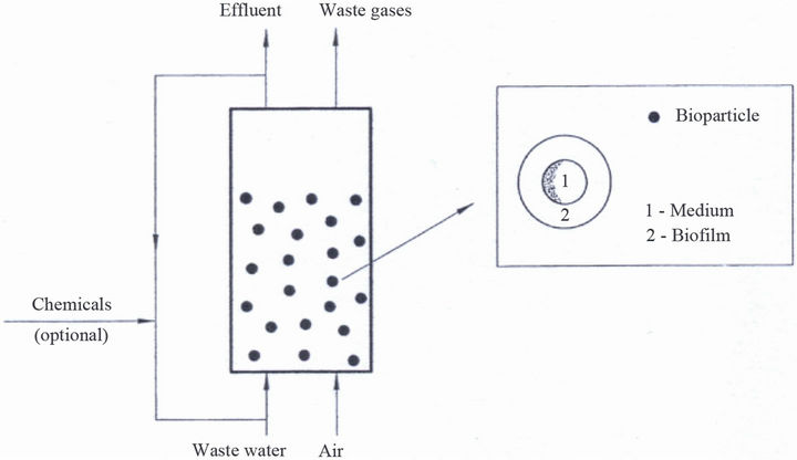
Figure 1. Scheme of the inverse fluidized bed biological reactor.
the bed expanding downwards into the less dense mixture of gas and liquid. In the latter, the bed is fluidized by a downward flow of a liquid counter to the net buoyancy force of the particles. At a small flow of the liquid, not sufficient to counter to the net buoyancy force, fluidization can be achieved by an adequate upward flow of the gas. The fluidization where fluidized bed expands downwards is termed the inverse fluidization.
In this study, the optimal aeration in the inverse FBBR, for which the largest COD removals were achieved, was determined for treatment of industrial wastewaters of various strengths. The polypropylene particles of density 910 kg/m3 were fluidized by an upward flow of air through a bed. Experiments on COD reduction were performed for the ratio of settled bed volume to reactor volume (Vb/VR) = 0.55, and various air velocities u and residence times t. The ratio (Vb/VR) = 0.55 was applied because for this value of (Vb/VR) Sokół and Korpal [1], and Sokół et al. [3] have obtained the largest reduction in COD in treatment of refinery wastewaters.
2. Experimentation
2.1. Experimental Set-Up
Experiments were conducted in the reactor shown in Figure 2. A growing medium, stored in a reservoir 1, was pumped into the bottom of the reactor by a centrifugal pump 5. Before entering the bed, the liquid was mixed with air by means of a sparger. The air was introduced to the bed through a distributor 7 whose plate had 200 holes of 4 mm diameter on a triangular pitch. The fluidised bed section 9, made of Duran glass, had a 20 cm internal diameter and was 6 m high. It was ended bya disengaging cap 10 with a 60 cm internal diameter and a height of 80 cm. The biomass sloughed off from the particles was separated from the effluent in a vessel 6 and removed from the system. The flow rate of the liquid was measured by a rotameter 4 and controlled by a ball valve. The air flow rate was measured using a rotameter 11 and controlled by a needle valve. The pH was adjusted by a control system 3, consisting of a pH-meter and micropumps supplying base or acid; as required. The temperature control system 2 consisted of a coil with cold water and an electric heater coupled with a contact thermometer.
The biomass support was the polypropylene particles of density 910 kg/m3 which are described elsewhere [9].
2.2. Feed and Microorganisms
The growing medium was the wastewater (Feed 1) taken from a local refinery. The Feed 1 was diluted so as to obtain the Feeds 2-6 whose composition is given in Table 1. The wastewaters were enriched in mineral salts by adding the following (mg/l): (NH4)2SO4—500; KH2PO4 —200; MgCl2—30; NaCl—30; CaCl2—20; and FeCl3— 7 [1].
The inoculum was the activated sludge taken from the biological treatment unit operated at the refinery.
2.3. Methodology
Sokół and Korpal [1] have established that the optimal ratio (Vb/VR) for a FBBR when used in biological wastewater treatment was equal to 0.55. Therefore, in this study experiments were performed for the ratio (Vb/VR) = 0.55.
2.3.1. Biomass Culturing
The particles and the growing medium (Feed 6) were introduced into the reactor to give a ratio (Vb/VR) = 0.55. To start growth of the microorganisms on the particles, a

Figure 2. Schematic diagram of the experimental apparatus: 1. Reservoir; 2. Temperature control system; 3. pH control system; 4. Liquid rotameter; 5. Pump; 6. Intermediate reservoir; 7. Air distributor; 8. Sampling; 9. Fluidized section; 10. Disengaging section; 11. Air rotameter.
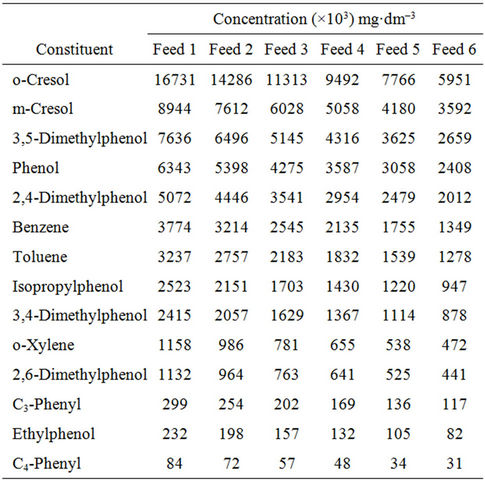
Table 1. Composition of wastewaters (feeds).
batch culture was first initiated by introducing about [5] of the inoculum into the reactor. Then the culture was incubated for approximately 48 h to encourage cell growth and the adhesion of freely suspended biomass on the particles. The air was supplied at the flow rate of 0.03 m3/s and this was found to be sufficient for biomass growth [1, 3]. The pH was controlled in the range 6.5 - 7.0 and the temperature was maintained at 28˚C - 30˚C.
When the biofilm had begun to grow on the particles, the growing medium was started to be pumped into the reactor at a dilution rate D = 0.40 h–1. This value of D corresponded to the smallest time t applied for Feed 6 (t = 1/D = 2.5 h in Figure 3). Next, the air velocity u was set at the smallest value applied for Feed 6 (u = 0.009 m/s in Figure 3) and the cultivation was continued until the constant biomass loading was achieved in a reactor.
The occurrence of the steady-state biomass loading was established by weighting the mass of cells grown on the support. The biomass was scraped from sample particles and dried at temperature 105˚C for 30 minutes. It
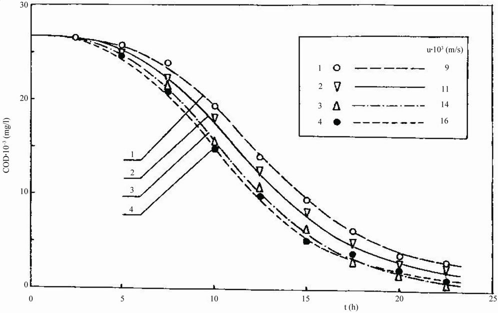
Figure 3. Dependence of chemical oxygen demand COD on residence time t for treatment of Feed 6.
was considered that the steady state occurred when the weight of biomass in two consecutive samples differed less than 5%. The steady-state biomass loading was attained in a reactor after the cultivation for approximately two weeks.
2.3.2. Treatment Operation
When the steady-state biomass loading was achieved, a sample liquid was withdrawn from the reactor and COD was measured by the procedure recommended by Verstraete and van Vaerenbergh [13]. It was established that once the constant biomass loading occurred in a reactor, the value of COD was practically at steady state.
Next, the air velocity u was increased stepwise to its next value applied for Feed 6 (u = 0.011 m/s in Figure 3) and the cultivation was continued until the new steadystate biomass loading was achieved. When this was attained, COD was measured by the method mentioned earlier [13]. These experiments for Feed 6 were conducted for all values of u shown in Figure 3.
Then the dilution rate D was decreased stepwise to its next value applied for Feed 6 (t = 1/D = 5 h in Figure 3) and the air velocity u was re-set to its smallest value applied for Feed 6 (u = 0.009 m/s in Figure 3). The cultivation was continued until the steady-state biomass loading was achieved. When this occurred, COD was measured following the procedure mentioned above [13]. These experiments were conducted for all air velocities u and times t shown in Figure 3. The results are given in Figure 3.
The above experiments were also performed for Feeds 1-5 (Table 1). The results are shown in Figures 4-8.
It should be pointed out that the air velocities u applied in the experiments were several times larger than the minimum fluidization air velocity uf. This was possible because the reactor was operated at the ratio (Vb/VR) = 0.55 which was smaller than the critical ratio (Vb/VR)cr [1, 9]. On the other hand, the air velocities u were smaller than the critical velocity ucr at which the entire bed settled at the reactor bottom.
3. Results and Discussion
It can be seen in Figures 3-8 that for a set time t, a concentration of COD in effluent depended on the air velocity u. A reduction in COD initially increased, and then decreased with an increase in u. For example, it can be noticed in Figure 4 that for a set t the values of COD were decreasing with an increase in u from 0.009 up to 0.014 m/s. A further increase in u did not improve a COD removal. The smallest value of COD was attained for um = 0.014 m/s. This can be explained by the fact that with an increase in u up to 0.014 m/s, an interfacial (air-

Figure 4. Dependence of chemical oxygen demand COD on residence time t for treatment of Feed 5.

Figure 5. Dependence of chemical oxygen demand COD on residence time t for treatment of Feed 4.
liquid) area increased, and consequently the amount of the oxygen supplied for biomass growth increased [1,14]. Thus, for the u smaller than 0.014 m/s, oxygen was the limiting factor for biomass growth. On the other hand,
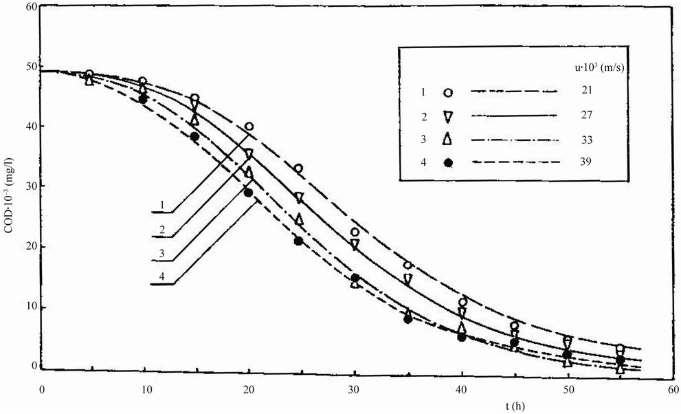
Figure 6. Dependence of chemical oxygen demand COD on residence time t for treatment of Feed 3.

Figure 7. Dependence of chemical oxygen demand COD on residence time t for treatment of Feed 2.
for the air velocities greater than 0.014 m/s, the degradation rate of the constituents of the wastewaters was the controlling factor of the treatment process [3,15].
As can be noticed in Figure 3, the value of COD was
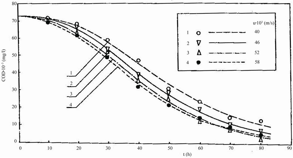
Figure 8. Dependence of chemical oxygen demand COD on residence time t for treatment of Feed 1.
practically at steady state for times t greater than 22.5 h. The largest COD removal occurred when the reactor was operated at (Vb/VR) = 0.55 and uopt = 0.024 m/s. A decrease in COD from 26,470 to 1180 mg/l, that is, a 96% COD reduction, was achieved when a reactor was optimally controlled at (Vb/VR) = 0.55, uopt = 0.014 m/s and t = 22.5 h.
The optimal air velocity uopt for which the largest decrease in COD was obtained strongly depended on value of COD (Figures 4-8).
The biomass loading was successfully controlled in a reactor containing low density particles used as biomass support. This was due to particle geometry and particularly availability of the internal surface and the grooves on external surface of the particles for biomass growth. With such geometry of the particles, shear forces occurring between the particles and the liquid sloughed off excess of biomass mainly from the external, and to less extend from the internal, surface of the particles. Furthermore, attrition, associated with particle-particle and particle-wall collisions, of biomass grown in the grooves and on the internal surface was less abrupt than the cells grown on the external surface of the particles.
The steady-state biomass loading in a reactor depended on an air velocity u. After change in u, the new steady-state biomass loading occurred after the culturing for about 2 days.
4. Conclusions
The optimal operating parameters for a reactor when used in treatment of industrial wastewaters were as follows: uopt = 0.052 m/s and ts = 80 h for CODo = 72,780 mg/l; uopt = 0.042 m/s and ts = 65 h for CODo = 62,070 mg/l; uopt = 0.033 m/s and ts = 55 h for CODo = 49,130 mg/l; uopt = 0.028 m/s and ts = 45 h for CODo = 41,170 mg/l; uopt = 0.025 m/s and ts = 27.5 h for CODo = 35,460 mg/l; and uopt = 0.014 m/s and ts = 22.5 h for CODo = 26,470 mg/l.
In a reactor controlled at the optimal values of uopt and ts, the following COD reductions were obtained: from 72,780 to 5410 mg/l; from 62,070 to 3730 mg/l; from 49,130 to 2820 mg/l; from 41,170 to 1820 mg/l; from 35,460 to 1600 mg/l; and from 26,470 to 1180 mg/l, i.e. a 93%, 94%, 95%, 96%, 95% and 96% COD removal was attained, respectively.
REFERENCES
- W. Sokół and W. Korpal, “Aerobic Treatment of Wastewaters in the Inverse Fluidised Bed Biofilm Reactor,” Chemical Engineering Journal, Vol. 118, No. 3, 2006, pp. 199-205. doi:10.1016/j.cej.2005.11.013
- P. Hüppe, H. Hoke and D. C. Hempel, “Biological Treatment of Effluents from a Coal Tar Refinery Using Immobilized Biomass,” Chemical Engineering Technology, Vol. 13, No. 1, 1990, pp. 73-79. doi:10.1002/ceat.270130110
- W. Sokół, A. Ambaw and B. Woldeyes, “Biological Wastewater Treatment in the Inverse Fluidised Bed Reactor,” Chemical Engineering Journal, Vol. 150, No. 1, 2009, pp. 63-68. doi:10.1016/j.cej.2008.12.021
- A. Lohi, M. Aivarez-Cuenca, G. Anania, S. R. Upreti and L. Wan, “Biodegradation of Diesel Fuel-Contaminated Wastewater Using a Three-Phase Fluidized Bed Reactor,” Journal of Hazardous Materials, Vol. 154, No. 1-3, 2008, pp. 105-111. doi:10.1016/j.jhazmat.2007.10.001
- M. Bajaj, C. Gallert and J. Winter, “Biodegradation of High Phenol Containing Synthetic Wastewater by an Aerobic Fixed Bed Reactor,” Bioresource Technology, Vol. 99, No. 17, 2008, pp. 8376-8381. doi:10.1016/j.biortech.2008.02.057
- P. A. Fitzgerald, “Comprehensive Monitoring of a Fluidized Bed Reactor for Anaerobic Treatment of High Strength Wastewater,” Chemical Engineering Science, Vol. 51, No. 11, 1996, pp. 2829-2834. doi:10.1016/0009-2509(96)00160-1
- R. Sowmeyan and G. Swaminathan, “Evaluation of Inverse Anaerobic Fluidized Bed Reactor for Treating High Strength Organic Wastewater,” Bioresource Technology, Vol. 99, No. 9, 2008, pp. 3877-3880. doi:10.1016/j.biortech.2007.08.021
- R. Sowmeyan and G. Swaminathan, “Performance of Inverse Anaerobic Fluidized Bed Reactor for Treating High Strength Organic Wastewater During Start-Up Phase,” Bioresource Technology, Vol. 99, No. 14, 2008, pp. 6280-6284. doi:10.1016/j.biortech.2007.12.001
- W. Sokół and M. R. Halfani, “Hydrodynamics of a GasLiquid-Solid Fluidized Bed Bioreactor with a Low Density Biomass Support,” Biochemical Engineering Journal, Vol. 3, No. 3, 1999, pp. 185-192. doi:10.1016/S1369-703X(99)00016-9
- W. Sokół, “Operational Range for a Gas-Liquid-Solid Fluidized Bed Aerobic Biofilm Reactor with a Low-Density Biomass Support,” International Journal of Chemical Reaction Engineering, Vol. 8, 2010, Article A111. http://www.bepress.com/ijcre/vol8/A111.
- L. Nikolov and D. Karamanev, “Experimental Study of the Inverse Fluidised Bed Biofilm Reactor,” Canadian Journal of Chemical Engineering, Vol. 65, 1987, No. 2, pp. 214-217. doi:10.1002/cjce.5450650204
- N. Fernandez, S. Montalvo, R. Borja, L. Guerrero, E. Sanchez, I. Cortes, M. F. Comenarejo, L. Traviso and F. Raposo, “Performance Evaluation of an Anaerobic Fluidized Bed Reactor with Natural Zeolite as Support Material When Treating High-Strength Distillery Wastewater,” Renewable Energy, Vol. 33, No. 11, 2008, pp. 2458-2466. doi:10.1016/j.renene.2008.02.002
- W. Verstraete and E. van Vaerenbergh, “Aerobic Activated Sludge,” In: W. Schonborn, Ed., Biotechnology, VCH Verlagessellschaft GmbH, Weinheim, 1986, pp. 43- 112.
- D. G. Karamanev, T. Nagamune and K. Endo, “Hydrodynamics and Mass Transfer Study of a Gas-Liquid-Solid Draft Tube Spouted Bed Bioreactor,” Chemical Engineering Science, Vol. 47, No. 13-14, 1992, pp. 3581-3588. doi:10.1016/0009-2509(92)85073-K
- W. Sokół and B. Woldeyes, “Evaluation of the Inverse Fluidized Bed Biological Reactor for Treating HighStrength Industrial Wastewaters,” Advances in Chemical Engineering and Science, Vol. 1, No. 4, 2011, pp. 239- 244.
Notation
COD: Chemical oxygen demand (mg/l);
D: Dilution rate (h–1);
t: Mean residence time (h);
u: Superficial upflow air velocity (m/s);
uf: Minimum fluidization air velocity (m/s);
ucr: Critical air velocity (m/s);
Vb: Volume of settled bed (m3);
VR: Reactor volume (m3).
Subscripts
o: Denotes initial (before treatment) COD value;
opt: Denotes values of air velocity giving the largest COD reduction;
s: Denotes steady-state.

