Agricultural Sciences
Vol.3 No.3(2012), Article ID:19039,8 pages DOI:10.4236/as.2012.33046
Effects of drip irrigation circuit design and lateral line lengths: I—On pressure and friction loss
![]()
1WRFI Department, National Research Center (NRC), Giza, Egypt; *Corresponding Author: tayelmynrc@yahoo.com
2Southern Illinois University Carbondale, Carbondale, USA
Received 7 January 2012; revised 13 February 2012; accepted 11 March 2012
Keywords: Drip; Irrigation; Circuit; Laterals; Pressure; Friction
ABSTRACT
Laboratory tests were conducted at the Irrigation Devices and Equipment’s Test Laboratory, Agricultural Engineering Research Institute, Agriculture Research Center, Giza, Egypt. The experimental design of laboratory experiments was split in randomized complete block design with three replicates. Laboratory tests carried out on three irrigation lateral lines of 40, 60, 80 m under the following three drip irrigation circuit (DIC) designs; 1) one manifold for lateral lines or closed circuits with one manifold of drip irrigation system (CM1DIS); 2) closed circuits with two manifolds for lateral lines (CM2DIS), and 3) traditional drip irrigation system (TDIS) as a control. The aims of the work were to study the effect of drip irrigation circuits (DIC) and lateral lines lengths (LLL; where): (LLL1 = 40 m, LLL2 = 60 m, and LLL3 = 80 m) on pressure head (PH) and friction loss (FL). Regarding to LLL and according to PH values, DIC designs could be ranked in the following ascending order: TDIS < CM1DIS < CM2DIS. The differences in PH among DIC designs were significant at the 1% level. The depressive effects of LLL on PH could be ranked in the following ascending order: LLL1 < LLL2 ≤ LLL3. Differences in PH among LLL treatments were significant at the 1% level except that between LLL2 and LLL3. The effects of interactions among: DIC × LLL on PH were significant at the 1% level with some exceptions. The highest value of PH (9.5 m) and the lowest one (6.05 m) were achieved in the interactions of CM2DIS × LLL1 and TDIS × LLL3, respectively. The shapes of the energy gradient lines were affected by DIC and LLL treatments used through their effect on ∆H/H ratio. However, they followed similar trends. According to the FL values, DIC and LLL treatments could be ranked in tha following descending orders TDIS > CM1DIS > CM2DIS and LLL1 > LLL2 > LLL3. The differences in FL among DIC and LLL were significant and the effects of interactions among DIC × LLL on FL were significant at the 1% level. The maximum and minimum values of FL were obtained in the interactions: TDIS × LLL3 and CM2DIS × LLL1, respectively. Therefore, the CM2DIS system is recommended for use where technically feasible.
1. INTRODUCTION
Differences in emitter geometry may be caused by variation in injection pressure and heat instability during their manufacture, as well as by a heterogeneous mixture of materials used for their production [1]. One some of the factors affecting drip irrigation design was inlet pressure. It was one of the most important factors in drip irrigation design. If the inlet pressure head becomes greater than the required pressure head; it may cause water back-flow and if the inlet pressure head becomes lower than the total required pressure head, it may create negative pressure at the lateral which will affect distribution uniformity. Consequently, to avoid both problems, the inlet pressure head must be determined precisely to balance the energy gain due to inlet flow and the total required pressure head within the lateral line [2]. [3,4] attempted a mathematical approach to calculate the inlet pressure head. In any irrigation system, energy required for system operation depends on the required head and the system discharge. [5] used the relationship:
 (1)
(1)
where: qe is the emitter flow rate (L3t–1); k is the emitter constant; x is the pressure head exponent; and H is pressure head (L).
[6] indicated that the relation between the flow rate and the pressure head is nonlinear in the transition and the turbulent flow types. Also he proposed a method to incorporate pipe components into the hydraulic network analysis by adding their contribution to the nodal equations instead of treating them as separate items. [7] used the Darcy-Wiesbach equation to evaluate the friction losses in a plastic pipe. He expressed the friction loss in the pipe as follows:
 (2)
(2)
where: hloss = Head loss (m), fs = the coefficient of friction (m/100 m); Q = the flow moving through the pipe (l·h–1); l = the pipe length (m); g = the gravitational acceleration (m/sec–2); and D = the pipe inside diameter (mm).
[2] used the Darcy-Wiesbach equation and calculated the value of fs. Based on the work of [7,8] they used their equation to calculate the friction coefficient based on the flow type being laminar, transient or turbulent. The local head loss is mainly due to friction losses in PE tubes and changes in water temperature in the lateral. Friction loss due to the velocity of water can be determined using Darcy-Weisbach equation. Although a single emitter generally produces a small local loss but due to the high number of emitters installed along a lateral, the total amount of local losses can become a significant fraction of the total energy loss [9]. [10] found that the head loss in elbows, tees, and valves can significantly affect the pressure in an irrigation network. [11] developed a computer model to optimize the irrigation system design for small areas in South Dakota, USA. The model considers crop type, soil type, irrigation interval, system layout, and pressure requirements of the emitter. Some of the parameters needed for the system design were calculated using the generalized equation for predicting parameters, such as the wetting diameter, the shortest irrigation interval, etc.
The manuscript aims to study the effect of drip irrigation circuits (DIC) used: 1) Closed irrigation circuit with one manifold for lateral lines (CM1DIS) 2) Closed irrigation circuit with two manifolds for lateral lines (CM2DIS), 3) traditional drip irrigation system (TDIS) as a control and lateral lines lengths (LLL): (LLL1 = 40 m, LLL2 = 60 m, LLL3 = 80 m) on: pressure head and friction loss.
2. MATERIAL AND METHODS
The laboratory tests were conducted at Irrigation Devices and Equipments Tests Laboratory, Agricultural Engineering Research Institute, Agriculture Research Center, Giza, Egypt. The experimental design of laboratory experiments was split in randomized complete block design with three replicates. Laboratory tests carried out on three irrigation lateral lines 40, 60, 80 m under the following three drip irrigation circuits (DIC) of: 1) one manifold for lateral lines or closed circuits with one manifold of drip irrigation system (CM1DIS); 2) closed circuits with two manifolds for lateral lines (CM2DIS), and 3) traditional drip irrigation system (TDIS) as a control, Figures 1-4 showed the directions of flow inside manifold and lateral tubes in the different DIC tested. Details of the pressure and water supply control have been described by [12]. Tests had been carried out in order to resolve the problem of lack of pressure head at the end of lateral lines in the TDIS.
Irrigation networks shown in Figures 1-3 included the following components: 1) Control head: It was located at the water source supply. It consists of a centrifugal pump 3''/3'', driven by electric engine (pump discharge of 80 m3/h and 40 m lift), sand media filter 48'' (two tanks),
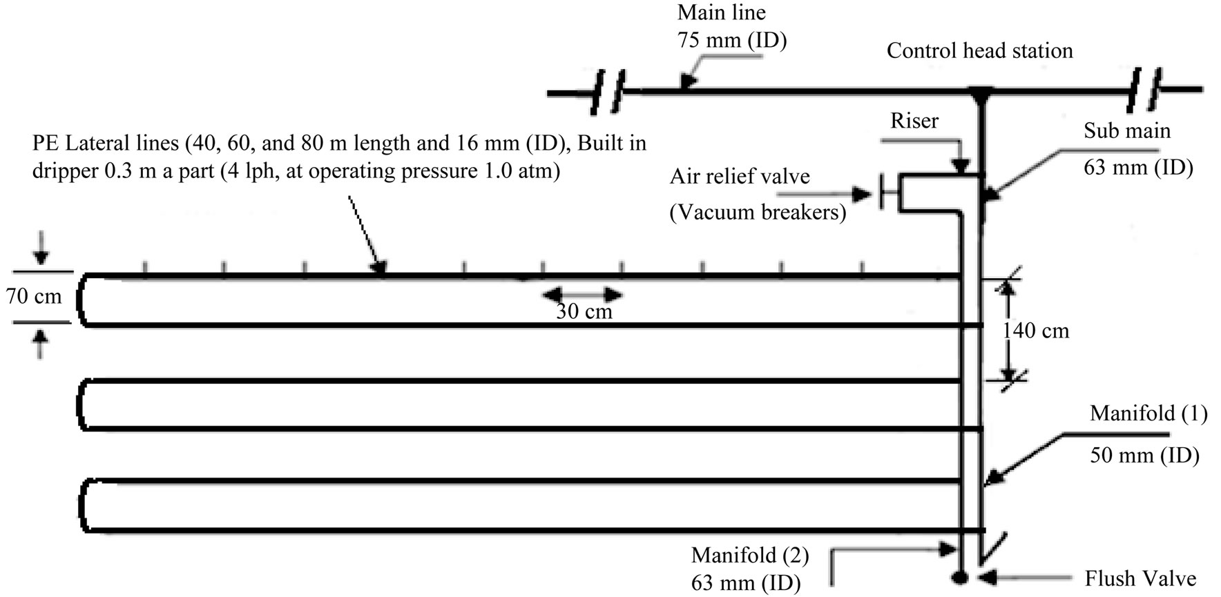
Figure 1. Layout of drippers in a closed circuit design with two manifolds (CM2DIS) for the lateral lines.
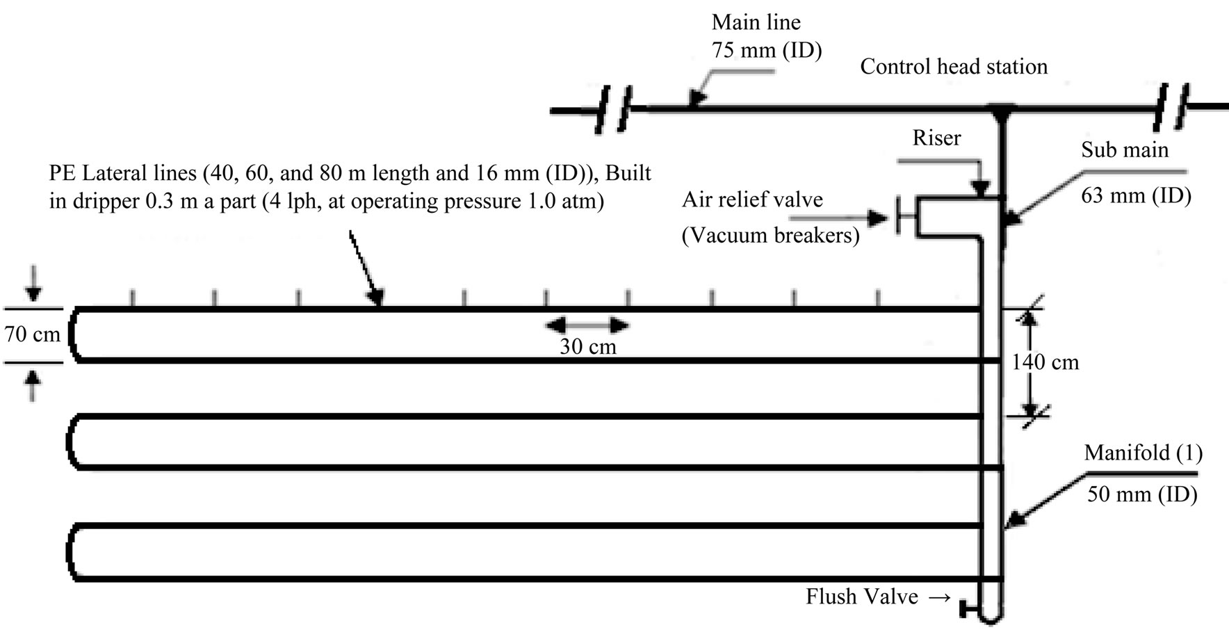
Figure 2. Layout of drippers in a closed circuit design with one manifold (CM1DIS) for the lateral lines.
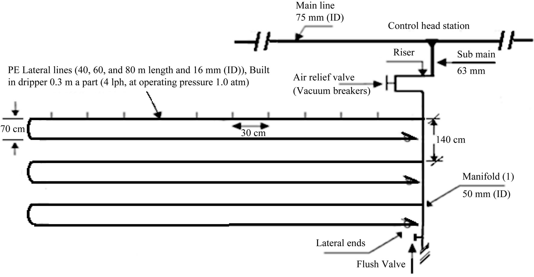
Figure 3. Layout of traditional drip irrigation system (TDIS).
screen filter 2'' (120 mesh), back flow prevention device, pressure regulator, pressure gauges, flow-meter, control valves and chemical injection port. 2) Main line: PVC pipes of 75 mm in (ID) to convey the water from the source to the main control points in the field. 3) Submain lines: PVC pipes of 75 mm in (ID) were connected to with the main line through a control unit consists of a 2'' ball valve and pressure gauges. 4) Manifold lines: PVC pipes of 50 mm in (ID) were connected to the sub main line through control valves 1.5''. 5) Lateral lines: PE tubes of 16 mm in (ID) were connected to the manifolds through beginnings stalled on manifolds lines. 6) Emitters: These emitters (GR) are built in PE tubes 16 mm in (ID), emitter discharge 4 l·h–1 at 1 atm. nominal operating pressure and 30 cm spacing in-between. The components of closed circuits of the drip system include, supply lines, control valves, supply and return manifolds, drip lateral lines, emitters, check valves and air relief valves/vacuum breakers [13].
The flow rate through the pipe depends on pipe surface roughness and air layer resistance. The change of hydraulic friction coefficient values, depending on variations in Re number values. Hydraulic losses at plastic pipes might be calculated as losses at hydraulically smooth pipes, multiplied by correction coefficients that assess losses at pipe joints and air resistance.
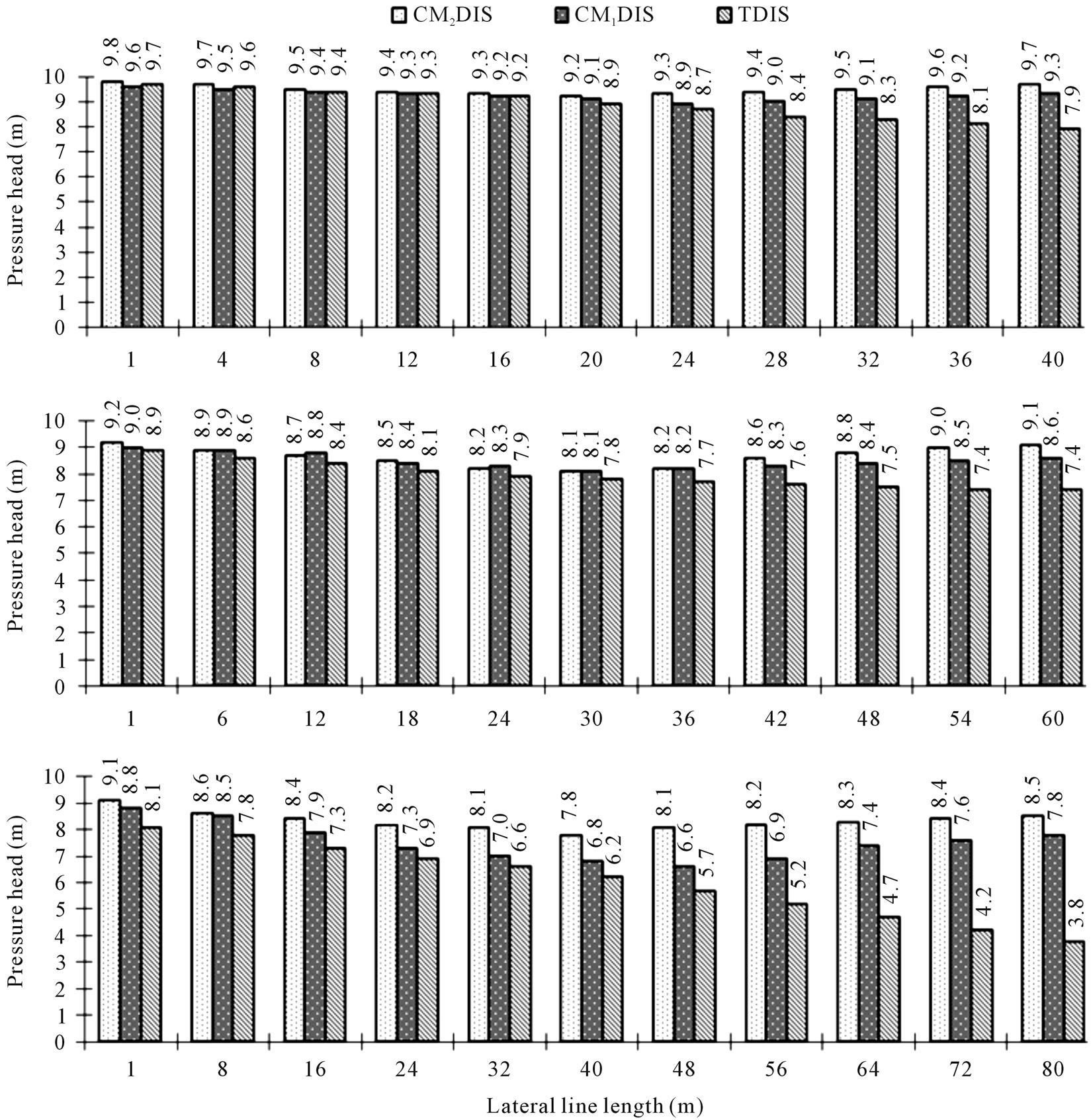
Figure 4. Effect of different irrigation circuits designs on pressure head along different lateral line lengths under (operating pressure = 1.0 atm and slope = 0%).
The energy loss (or head loss) in pipes due to water flow is inversely proportional to the pipe’s length.
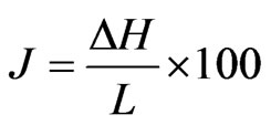 (3)
(3)
where J = The head loss coefficient in a pipe is usually (%) or m/100 m∆H = change in water head (m), and L = length of tube (m).
Coefficient of friction loss was given by [14,15]. The head loss due to friction is calculated by Hazen-Williams equation:
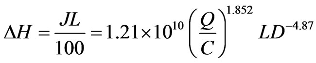 (4)
(4)
whereΔH = Head loss due to friction (m), J = coefficient of head loss (m/100 m) or %, Q = flow rate is (m3/h)L = pipe length (m), D = (inner diameter) ID Ø of a pipe (mm), and C = (Hazen-Williams coefficient) smoothness (the roughness) of the internal pipe, (the range for a commercial pipe is 80 - 150). For polyethelene tubes when ID < 40 mm C = 150 [14,15]. [16] stated that head loss due to friction was calculated using the following Darcy-Weisbach equation:
 (5)
(5)
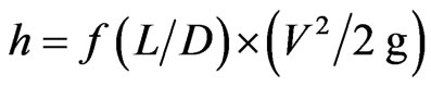
where h = head loss, m; f = friction factor ; L = length of pipe, m; D = ID Ø of pipe work, m; v = velocity of fluid, m/s; g = acceleration due to gravity, m/s–2.
Friction factor can be expressed as:
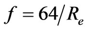 (For Re ≤ 2000)(6)
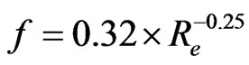 (For Re ≥ 2000) (7)
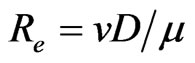
where Re = Reynolds’ number, which can be expressed as:
 (8)
(8)
Where v = fluid velocity, m/sec; D = ID Ø of lateral, m; and µ = kinematic viscosity of water = 1 × 10⁻⁶ m2/sec, at 20˚C.
Velocity v (m/s) can be expressed as:
 (9)
(9)
where, Q = lateral flow rate (m3∙sec–1) (average flow rate per emitter × number of emitters), and A = cross sectional area of lateral (m2).
MSTATC program (Michigan State University, East Lansing, MI, USA) was used to carry out statistical analysis. Treatments mean were compared using the technique of analysis of variance (ANOVA) and the least significant difference (L.S.D) between systems at 1% [17].
3. RESULTS AND DISCUSSION
Table 1 and Figures 4 and 5 showed the effect of the DIC used; closed DIC having two and/or one manifolds (CM2DIS; CM1DIS), TDIS and LLL (LLL1 = 40 m, LLL2 = 60 m; LLL3 = 80 m) on the parameter under investigation. It can be noticed that PH decreased along the LLL up to 50% - 60% of its length then, it increased again to reach nearly its inlet head pressure in both CM2DIS and CM1DIS. On the other hand, it decreased continuously with distance from lateral line inlet in TDIS. This may be due to the existence of two inlets in both CM2DIS and CM1DIS which cut down the LLL by about 50% - 60%. According to the Hazen-Williams equation; there is a direct relation between LLL and friction loss. Differences in PH between CM2DIS and CM1DIS may be explained on the basis that lateral lines are supplied with water from two manifolds and one manifold, respectively. In other words, the inlet pressure was higher in CM2DIS relative to CM1DIS, due to doubling the cross sectional area of the manifolds and that they are connected in parallel in CM2DIS. Whereas in CM1DIS, manifold is connected in series and both manifold length (Lm) and resistance increased (Figures 1 and 2).
Regardless of LLL, and according the PH values, DIC used could be ranked in the following ascending order: TDIS < CM1DIS < CM2DIS. Difference in PH between any two DIC values was significantly at the 1% level.
Concerning the depressive effect of LLL on PH, LLLs could be ranked in the following ascending order: LLL1 < LLL2 = LLL3. Differences in PH between LLL1 from one side and both LLL2 and LLL3 from the other one were significant at the 1% level. This is due to the direct
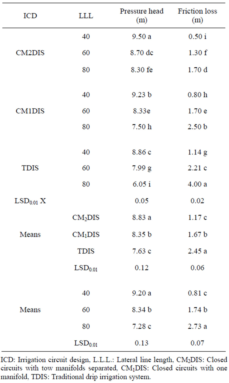
Table 1. Effect of drip irrigation circuits (DIC) on pressure head and friction loss (operating pressure = 1 atm and slope = 0%).
relation between friction and both lateral line discharge and its length.
The effect of DIC × LLL on PH was significant at the 1% level except between the two interactions: CM2DIS × LLL3 and CM1DIS × LLL2. The highest (9.5 m) and the lowest (6.05 m) values of PH were achieved in the interactions: CM2DIS × LLL1 and TDIS × LLL3, respectively.
It is worthy to mention that the allowable drop in pressure between the maximum and minimum pressure along the lateral lines must be ≤1.1 m under turbulent flow condition. This is very necessary for drip irrigation system to be economic and water and fertilizers distribution along the lateral to be acceptable. Data, indicated that all LLL of 16 mm inside Ø under TDIS and that of 80 m in length under CM2DIS and CM1DIS were not recommended to avoid high cost and the lower uniformity of both water and fertilizers distribution along the
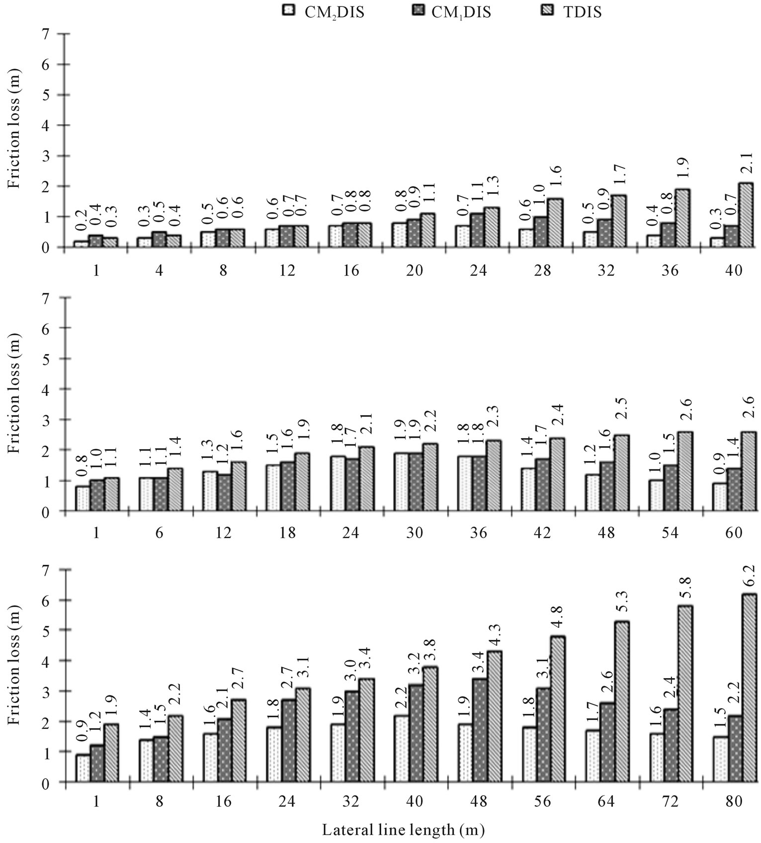
Figure 5. Effect of different irrigation circuits designs on friction loss along different lateral line lengths under (operating pressure 1.0 atm and slope = 0%).
LLL. Therefore, for 16 mm inside Ø and 80 m long laterals, either LLL should be shorten or their inside Ø should be increased.
Data given in Table 1 and plotted in Figure 5 indicated that the change in friction loss took an opposite trend to that of PH. Friction loss increased with distance from lateral inlet reaching its maximum at 50% to 60% of lateral length, then it decreased again up to the lateral line end in the case of using CM2DIS and CM1DIS. In other words, the minimum values of friction loss existed at both the inlets and the end of the lateral lines. Reasons for this are due to the direct relation between friction loss from one side and its length and discharge from the other side.
According to the friction loss values, DIC could be ranked in the following descending order: TDIS > CM1DIS > CM2DIS. Differences in friction loss between any two DIC were significant at the 1% level.
The ascending order: LLL1 < LLL2 < LLL3 illustrated the mean effect of LLL on friction loss. Differences in friction loss among LLL treatments were significant at the 1% level.
The effect of the DIC × LLL on friction loss was significant at the 1% level. The maximum and minimum values of friction loss were obtained in the interactions: TDIS × LLL3 and CM2DIS × LLL1, respectively.
As the flow rate in lateral line decreases (with respect to its length due to dripper discharges from the lateral lines) the energy gradient line will not be a straight line but a curve of an exponential type Figures 6-8. This is in agreement with [18,19]. [19] mentioned that only the total friction drop ratio (∆H/H) affected the shape of the energy gradient lines. It is clear from Figures 6-8 that all factors affecting the ratio (∆H/H) including DIC and
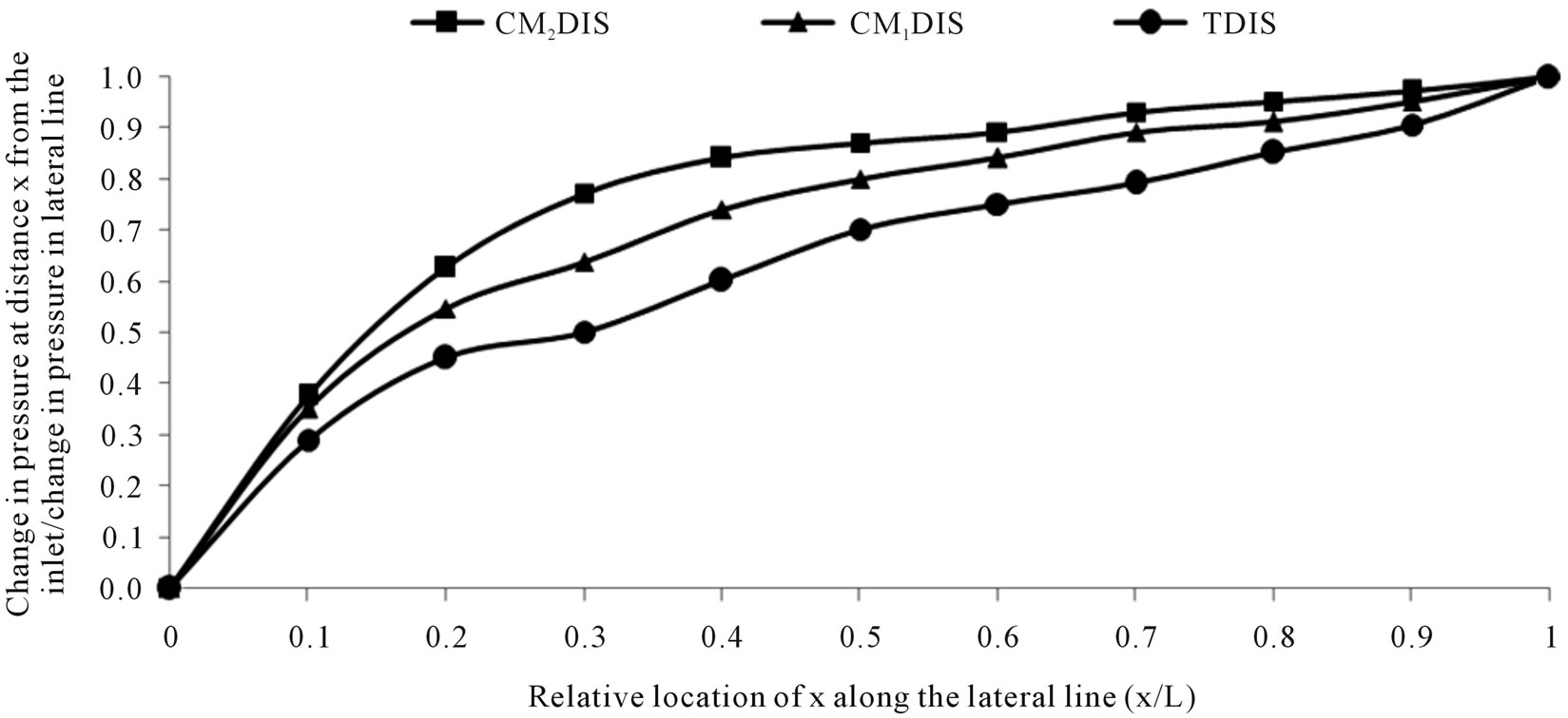
Figure 6. Dimensionless curves showing the friction drop pattern in drip lateral line under different irrigation circuits (lateral line length = 40 m, operating pressure = 1.0 atm and slope = 0%).
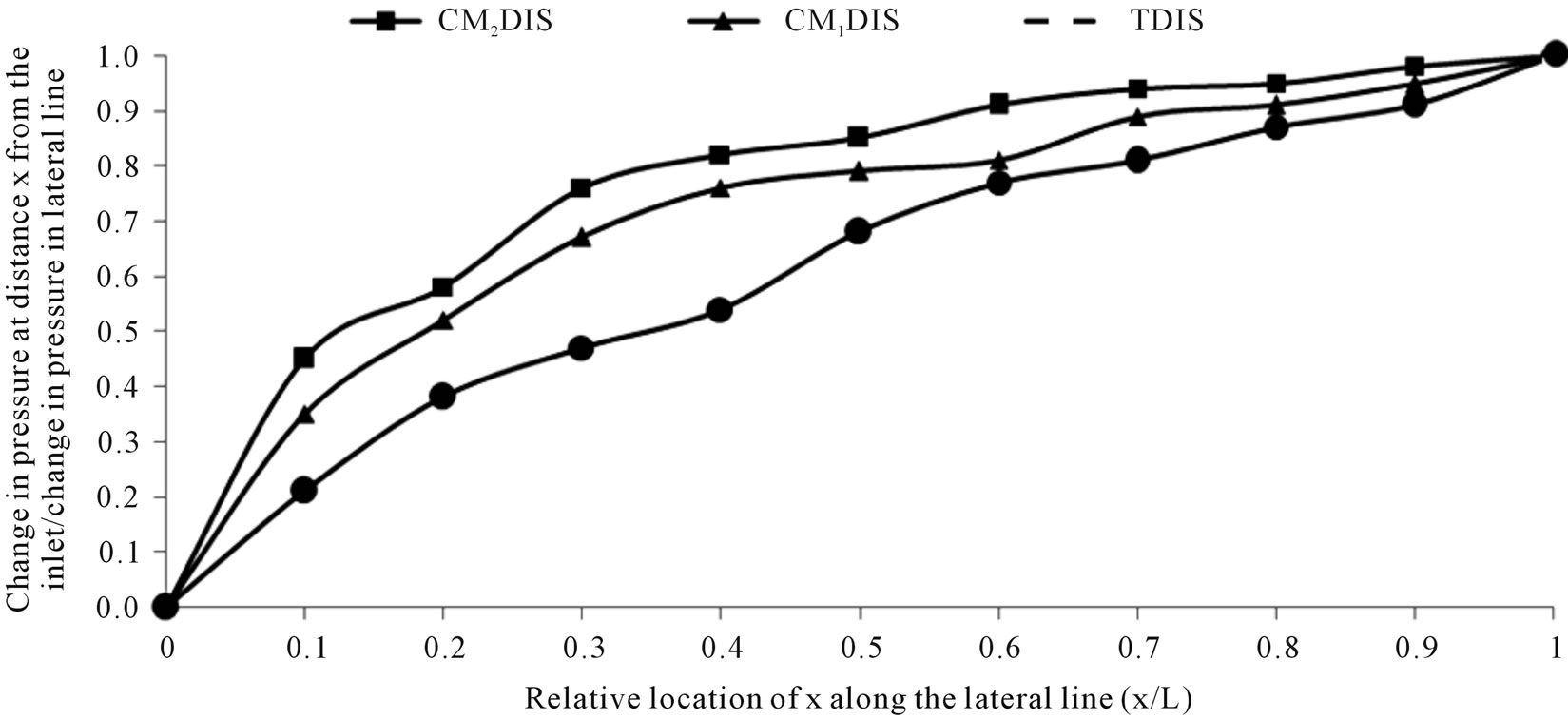
Figure 7. Dimensionless curves showing the friction drop pattern in drip lateral line under different irrigation circuits (lateral line length = 60 m, operating pressure = 1.0 atm and slope = 0%).
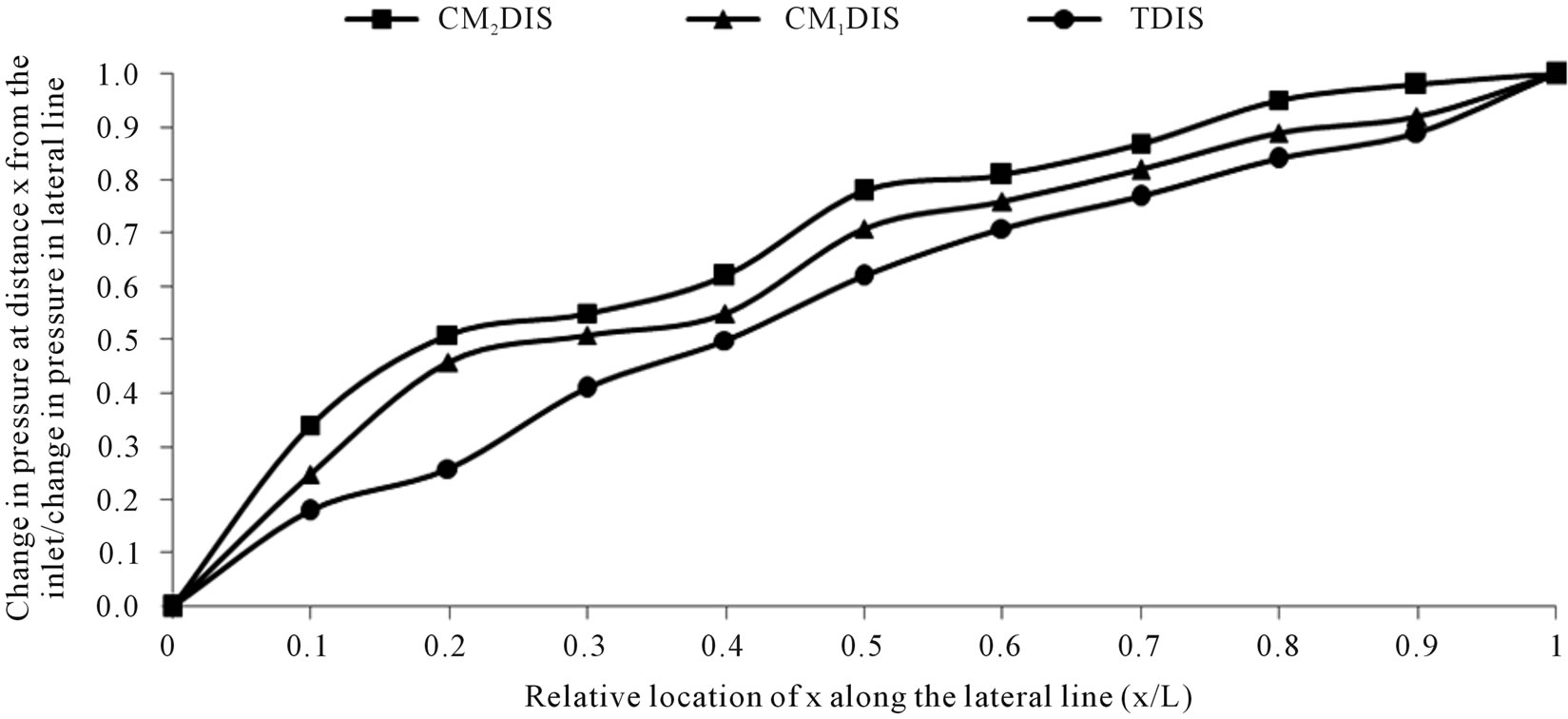
Figure 8. Dimensionless curves showing the friction drop pattern in drip lateral line under different irrigation circuits (lateral line length = 80 m, operating pressure = 1.0 atm and slope = 0%).
LLL used also affected the shape of the energy gradient lines.
4. SUMMARY AND CONCLUSIONS
Closed-circuits designs were proposed as incorporating modifications to the TDIS. There were seven major conclusions from the work:
1) From LLL and PH values, DIC could be ranked in the following ascending order: TDIS < CM1DIS < CM2DIS. The differences in PH among DIC were significant at the 1% level.
2) The depressive effects of LLL on PH could be ranked in the following ascending order: LLL1 < LLL2 ≤ LLL3. Differences in PH among LLL treatments were significant at the 1% level except that between LLL2 and LLL3.
3) The effects of interactions: DIC X LLL on PH were significant at the 1% level with some exceptions.
4) The highest value of PH (9.5 m) and the lowest one (6.05 m) were achieved in the interactions: CM2DIS × LLL1 and TDIS × LLL3, respectively.
5) The shapes of the energy gradient lines were affected by DIC and LLL treatments used through their effect on ∆H/H ratio, but they took the same trend.
6) According to the FL values, DIC and LLL treatments could be ranked in the following descending orders: TDIS > CM1DIS > CM2DIS and LLL1 > LLL2 > LLL3, respectively. The differences in FL among DIC and LLL were significant at the 1% level.
7) The effects of interaction: DIC X LLL on FL were significant at the 1% level. The maximum and minimum values of FL were obtained in the interactions: TDIS × LLL3 and CM2DIS × LLL1, respectively.
Therefore, the CM2DIS system is recommended for use where technically feasible.
REFERENCES
- Kirnak, H., Dogan, E., Demir, S. and Yalcin, S. (2004) Determination of hydraulic performance of trickle irrigation emitters used in irrigation system in the Harran Plain. Turkish Journal of Agriculture and Forestry, 28, 223- 230.
- Hathoot, H.M., Al-Amoud, A.I. and Mohammed, F.S. (1993) Analysis and design of trickle irrigation laterals. Journal of Irrigation and Drainage Engineering, 119, 756-767. doi:10.1061/(ASCE)0733-9437(1993)119:5(756)
- Yildirim, G. and Agiralioglu, N. (2008) Determining operating inlet pressure head incorporating uniformity parameters for multi outlet plastic pipelines. Journal of Irrigation and Drainage Engineering, 134, 341-348. doi:10.1061/(ASCE)0733-9437(2008)134:3(341)
- Deba, P.D. (2008) Characterization of drip emitters and computing distribution uniformity in a drip irrigation system at low pressure under uniform land slopes. M.Sc. Thesis, Texas A&M University.
- Bralts, V.F., Edwards, D.M. and Wu, I.-P. (1987) Drip irrigation design and evaluation based on the statistical uniformity concept. Advances in Agronomy, 4, 67-117.
- Gerrish, P.J., Shayya, W.H. and Bralts, V.F. (1996) An improved analysis of incorporating pipe components into the analysis of hydraulics networks. Transactions of the ASAE, 39, 1337-1343.
- Von Bernuth, R.D. (1990) Simple and accurate friction loss equation for plastic pipes. Journal of Irrigation and Drainage Engineering, 116, 294-298. doi:10.1061/(ASCE)0733-9437(1990)116:2(294)
- Hathoot, H.M., Al-Amoud, A.I. and Mohammed, F.S. (1991) Analysis of a pipe with uniform lateral flow. Alexandria Engineering Journal, 30, C49-C54.
- Smajstrla, A.G. and Clark, G.A. (1992) Hydraulic performance of microirrigation drip tape emitters. ASAE Paper No. 92-2057. http://www.toromicroirrigation.com
- Wood, D.J. and Rayes, A.G. (1981) Reliability of algorithms for pipe network analysis. Journal of the Hydraulics Division, 107, 1145-1161.
- Narayanan, R., Steele, D.D. and Scherer, T.F. (2000) Computer model to optimize above-ground drip irrigation systems for small areas. Applied Engineering in Agriculture, 18, 459-469.
- Safi, B., Neyshabouri, M.R., Nazemi, A.H., Masiha, S. and Mirlatifi, S.M. (2007) Subsurface irrigation capability and effective parameters on onion yield and water use efficiency. Journal of Scientific Agricultural, 1, 41-53.
- Netafim Irrigation, Inc. (2002) Bioline design guild. http://www.netafim.com
- Mogazhi, H.E.M. (1998) Estimating Hazen-Williams coefficient for polyethylene pipes. Journal of Transportation Engineering, 124, 197-199. doi:10.1061/(ASCE)0733-947X(1998)124:2(197)
- Bombardelli, F.A. and Garcia, M.H. (2003) Hydraulic design of largediameter pipes. Journal of Hydraulic Engineering, 129, 839-846. doi:10.1061/(ASCE)0733-9429(2003)129:11(839)
- Hathoot, H.M., Al-Amoud, A.I. and Mohammed, F.S. (1994) The accuracy and validity of Hazen-Williams and scobey pipe friction formulas.” Alexandria Engineering Journal, 33, C97-C106.
- Steel, R.G.D and Torrie, J.H. (1980) Principles and procedures of statistics. A biometrical approach. 2nd Edition, McGraw Hill Inter Book Co, Tokyo.
- Bazaraa, A.S. (1982) Pressurized irrigation systems sprinkler and trickle irrigation. Faculty of Engineering, Cairo University, Cairo.
- Wu, I.P. (1992) Energy gradient line approach for direct hydraulic calculation in drip irrigation design. Irrigation Science, 13, 21-29. doi:10.1007/BF00190241