Journal of Minerals and Materials Characterization and Engineering
Vol.1 No.5(2013), Article ID:37217,14 pages DOI:10.4236/jmmce.2013.15040
Thermodynamic Calculation for Silicon Modified AISI M2 High Speed Tool Steel
Steel Technology Department, Central Metallurgical R&D Institute (CMRDI), Helwan, Egypt
Email: hossamhalfa@cmrdi.sci.eg
Copyright © 2013 Hossam Halfa. This is an open access article distributed under the Creative Commons Attribution License, which permits unrestricted use, distribution, and reproduction in any medium, provided the original work is properly cited.
Received June 8, 2013; revised July 12, 2013; accepted July 23, 2013
Keywords: Phase Diagram; High Speed; Silicon; Carbides; Thermo-Calc
ABSTRACT
During high speed tool steel production up to 0.2 wt % silicon is added, primarily to react with oxygen e.g. silicon acts as a de-oxidizer. If more than 0.2 wt % silicon is added, it serves to improve the deep hardening properties. An addition up to ~1 wt % silicon provides hardness and improves temper-stability but reduces the ductility. At high concentration, silicon causes embrittlement. Alloying with silicon raises the solubility of carbon in the matrix and hence the as-quenched hardness. It has virtually no influence on the carbide distribution, but it promotes the formation of M6C type carbides. The many essential alloy additions to iron (C, W, Mo, V, Cr, Si) make the high speed tool steel, HSS a complex multi-component system. Its complete experimental investigation would require enormous time and effort. Instead, the CALPHAD method has been successfully used for computation of phase equilibrium the multi-component HSS system. In the present work, the Thermo-Calc program has been applied to the system Fe-C-Cr-W-Mo-V-Si with the thermodynamic information contained in the solid-solution-database of the TCFE. In the present work, some temperature-concentration diagrams for silicon modified AISI M2 steel are presented by calculated quantities (melting and transformation temperatures, amount and compositions of phases). Calculated data are compared with standard AISI M2 high speed tool steel.
1. Introduction
High-speed steels are used for applications requiring long life at relatively high operating temperatures such as for heavy cuts or high-speed machining. High-speed steels are the most important alloy tool steels because of their very high hardness and good wear a resistance in the heat-reacted condition and their ability to retain high hardness and the elevated temperatures often encountered during the operation of the tool at high cutting speeds [1-3].
During steel production up to 0.2 wt % silicon is added, primarily to react with oxygen e.g. silicon acts as a deoxidizer. It makes steel sound, by removing oxygen bubbles from the molten steel. The percentage of silicon in the analysis was related to the type of steel, rimmed and capped steels (made by the ingot method) had no silicon intentionally added. Semi-killed steels typically contained up to 0.10% max silicon, and fully killed steels could have up to 0.60% maximum [4].
In addition to deoxidiation silicon also influences the steel five different ways [5]:
1) Silicon helps increase the steel’s strength and hardness, but is less effective than manganese in these functions.
2) In electrical and magnetic steels, silicon helps to promote desired crystal orientations and electrical resistivity.
3) In some high temperature service steels, silicon contributes to their oxidation resistance.
4) In alloy grades, silicon also increases strength (but not plasticity) when quenched and tempered.
5) Silicon also has a moderate effect on harden ability of steel.
But there are always less desirable aspects of any element in an alloy
• Silicon is detrimental to surface quality in low carbon steels, a condition that is especially magnified in low carbon resulfurized steels.
• Silicon is detrimental to tool life in machining as it forms hard abrasive particles which increase tool wear and thus lower the steel’s machinability.
The variety of the alloy additions occurring in the high-speed steels (C, W, Mo, V, Si, Cr,) makes them the extraordinarily complex multi-phase system. The diversity of transformations, physical relationships, decides that their structural investigations call for using the most subtle investigation methods employed in the materials engineering.
Alloying with silicon raises the solubility of carbon in the matrix and hence the as-quenched hardness. It has virtually no influence on the carbide distribution [6], but it promotes the formation of M6C type carbides [7,8].
In the present work, the Thermo-Calc program has been applied to the system Fe-C-Cr-W-Mo-V-Si with the thermodynamic information contained in the solid-solution-database of the TCFE. In the present work, some temperature-concentration diagrams for silicon modified AISI M2 steel are present and calculated quantities (melting and transformation temperatures, amount and compositions of phases). Calculated data are compared with standard AISI M2 high speed tool steel.
2. Experimental Work
2.1. Melting and Casting
To study the effect of silicon as alloying element, four alloying chemical composition range from 0 wt % silicon to 5 wt % silicon based on high speed tool steel AISI M2 were investigated. Five kilograms of each of the high speed tool steel AISI M2 alloys were melted from pure elements in a skull induction-melting furnace (ISM), which employed a water-cooled copper crucible. High purity argon was used as an inert gas, and titanium getters were melted to minimize interstitial gases including oxygen and nitrogen from the furnace atmosphere before melting.
New and developed batch of high speed tool steel AISI M2 was loaded into the skull induction melting furnace crucible under vacuum with pressure 1 × 10⁻³ mbar. The entire crucible was inductively heated noting the power
(based on voltage, current, and time at each setting) required for melting. The skull induction melting ingot was melted two times, inverting the ingot after each melting to ensure homogeneity. Cylindrical samples were obtained by drop casting into a Cu-mould of diameter 60 mm.
2.2. Thermo-Calc Experimental
The data for all edge binaries with Fe and C, Fe-M, and C-M, as well as for ternaries Fe-C-M (M = metal), are contained in the optimized TCFE database, together with data for other edge binaries and higher-order systems (M1-M2, M1-M2-C, M1-M2-Fe.). All phases in the database are described according to a sub-lattice model [9, 10]. Phases other than those in Table 1 have not been considered as possible stable phases in the calculations performed here, since they have not been reported in real high-speed-steel alloys.
It is important to mention that such a data base represents years of research with thousands of single measurements. The data base may be incomplete, or the models used to generate it may not be perfect, but it provides the most reliable prediction of phase relations available, though not the only possible ones.
2.3. Testing
The remelted ingots were cut in the longitudinal and transverse directions to physically examine the presence of any cavity or holes. All alloy samples under investigation were examined by radiographic tests to ensure that they were free from solidification defects.
Compositional analysis of the produced ingots was evaluated by standard gravimetric wet analytical techniques and further substantiated by induction-coupled plasma atomic emission (ICP-AES) technique. Carbon was analyzed using a gas analysis technique using a Leco
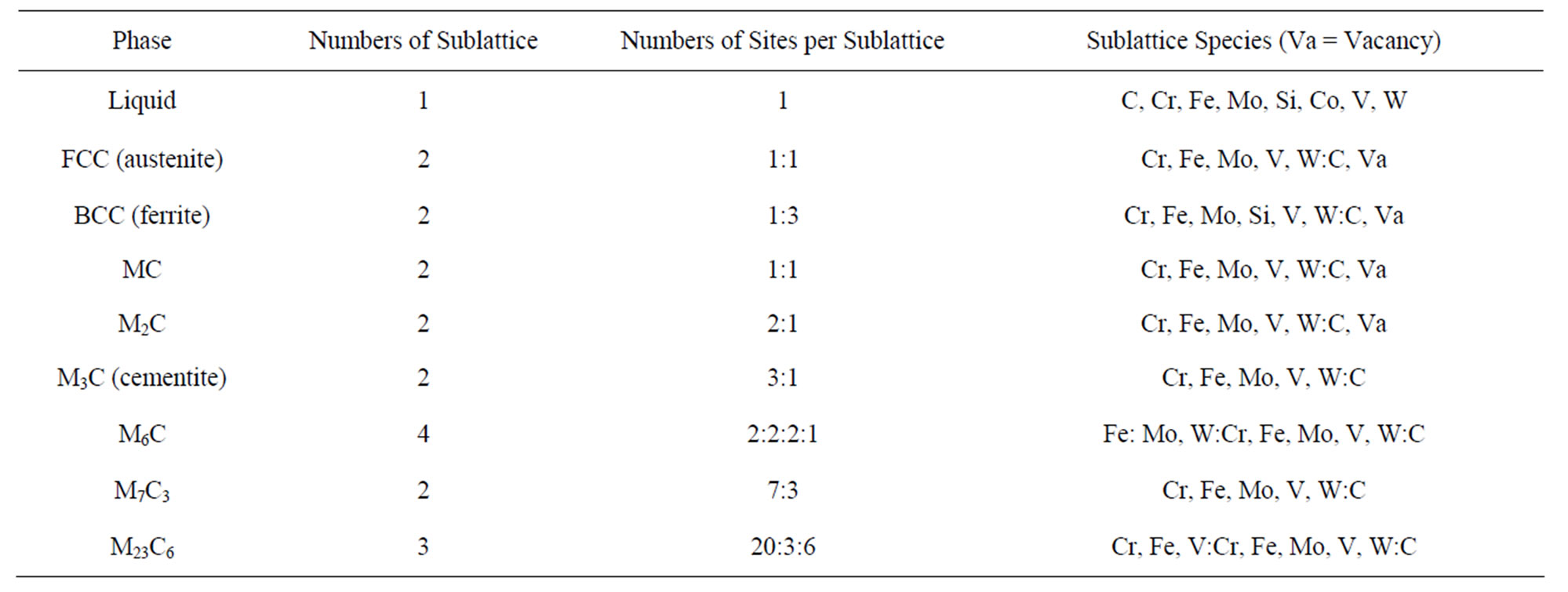
Table 1. Models of the phases considered in the calculations.
gas analyzer.
2.4. Qualitative Carbide Description
In order to determine the nature of the different carbides encountered in the studied material, a Nital (3%) etching was made on a polished samples coming from the top and the bottom of the ingots were taken both at the center, half radius and the edge. The nature of the carbides is determined by means of electron microscopy (SEM and EDX), and the results are given in Table 2. It is well known that four groups of carbides were presence in HSS M2:MC (rich in V), M2C (rich in Mo), M6C (rich in W and Mo) in addition to M7C3 and M23C7 carbides which rich in Cr. Furthermore, Groesbeck’s reagent [11] was used to differentiate each group of carbides, by means of optical microscopy. MC carbides are not etched and appear in pink in the matrix; M2C in dark brown and M7C3-M6C in blue or yellow. Both M6C and M7C3, which are always associated and have the same colour, have to be considered as a whole when using optical microscopy.
2.5. Image Processing
First, carbides and matrix are separated by a simple thresholding. Because the etching is not totally reproducible from one sample to another and sometimes heterogeneous on the sample surfaces, the operator for every image chooses threshold levels interactively. Secondly, isolated MC carbides are easily extracted thanks to their average gray level. After these two first operations, unclassified pixels are MC, M23C6 and M7C3-M6C carbides belonging to clusters.
Pixels are finally assigned to one of the three carbide types (MC, M23C6 and M7C3-M6C) on the basis of their gray level value and of some criteria. For example, around and inside M23C6-M7C3-M6C carbides, matrix is digitized by pixels with gray level values equal to those of the MC because they are a transition between a bright matrix and darker carbides. So, one criterion is to assign these pixels to the matrix. Three binary images of every kind of carbides are finally obtained. Any combination of these images can be considered, like image of all carbides.
3. Results and Discussions
The alloys presented in Table 3 correspond to the classical HSS 6-5-2 (AISI M2) and to some of their siliconalloyed variant.
3.1. Temperature-Concentration Sections
High-speed tool steels are complex, multi-component alloy systems in which microstructures are very dependent on the kinetics of solidification and solid-state reactions and the non-uniform distributions of phases that accom-
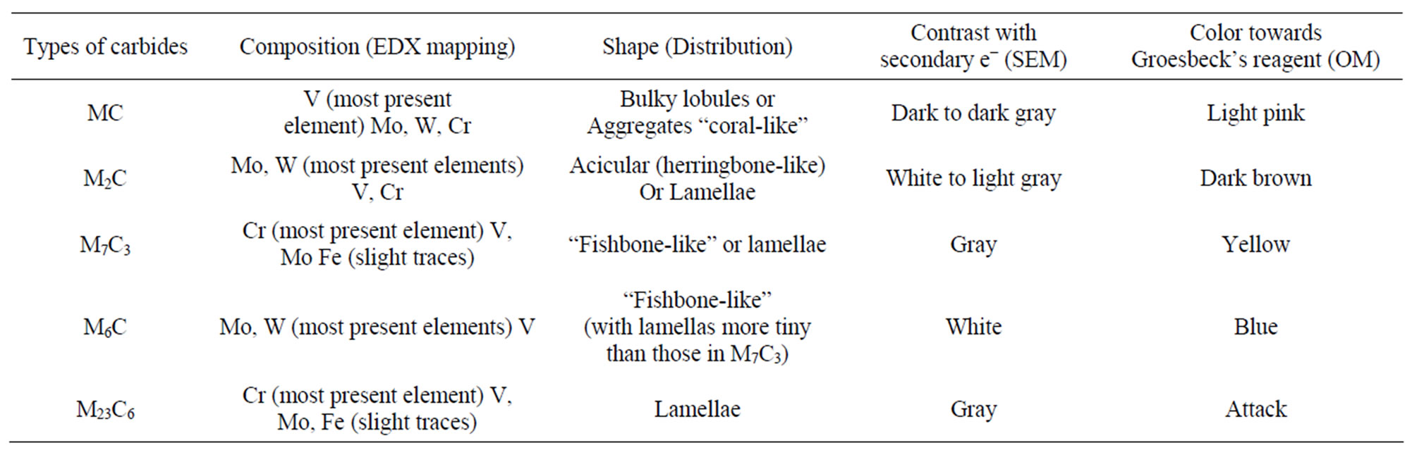
Table 2. General characterization of carbides in investigated high speed tool steel.
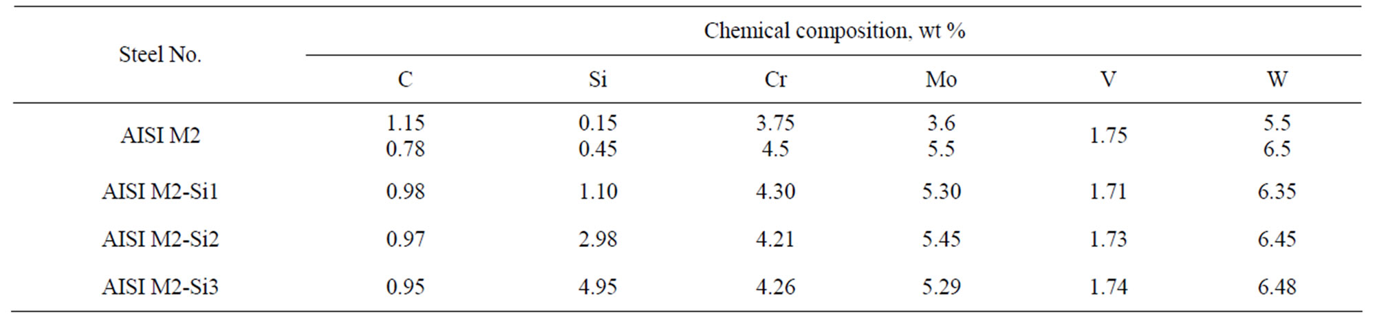
Table 3. Chemical composition of the investigated steels (wt %).
pany these reactions. Following Hoyle [12], the best way to rationalize the microstructural changes that occur during the processing of high-speed tool steels is to consider vertical sections through the multi-component systems that make up these steels. The vertical sections plot regions of phase stability as a function of temperature and carbon content but do not give the compositions of the coexisting phases or the configuration of the phases. Nevertheless, the vertical sections indicate when various phases must form during processing, and this information together with other observations provides a good understanding of the evolution of microstructure in high-speed steels.
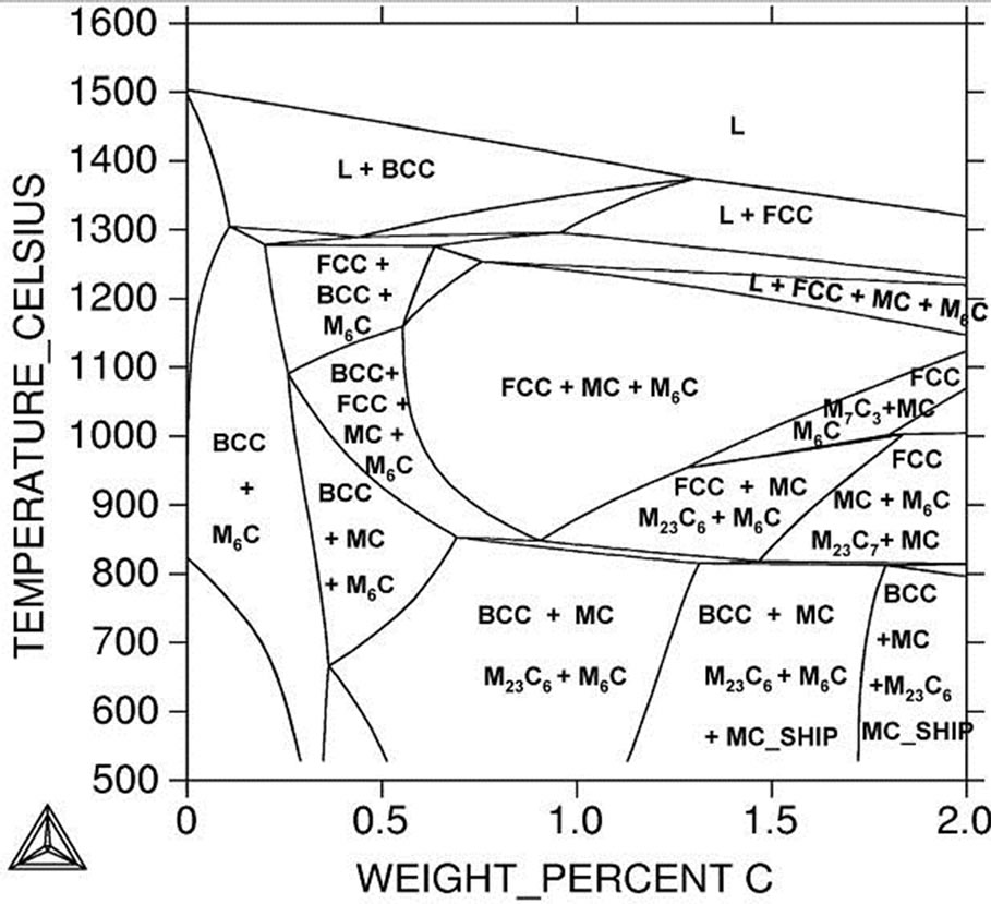
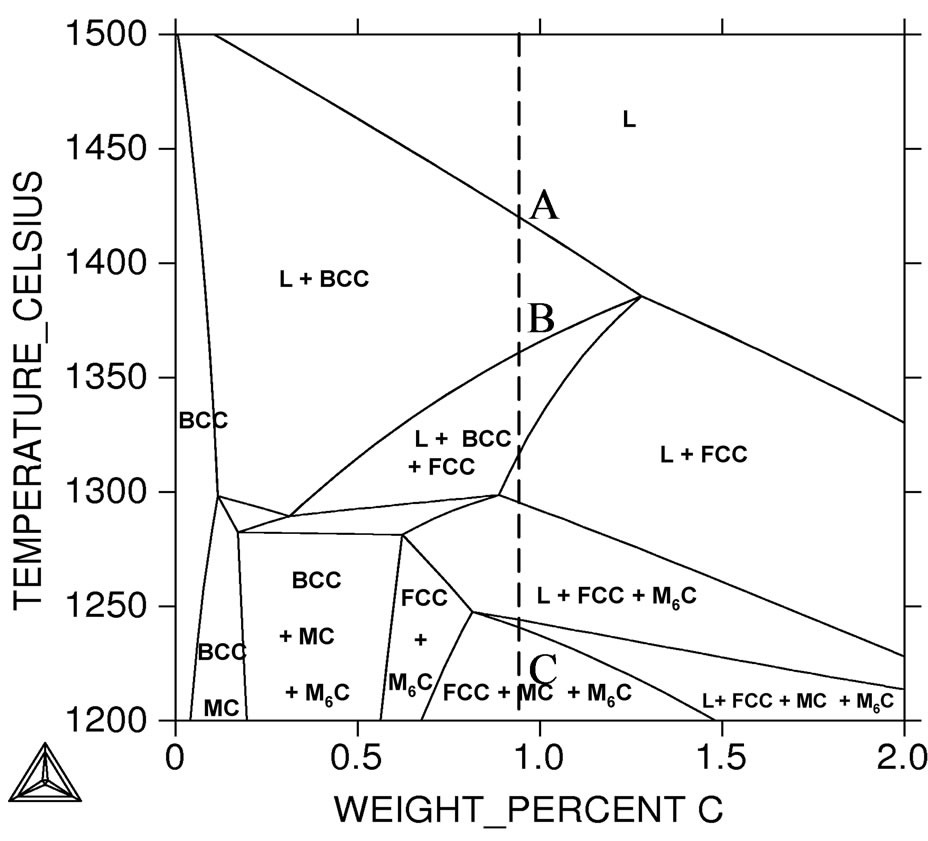
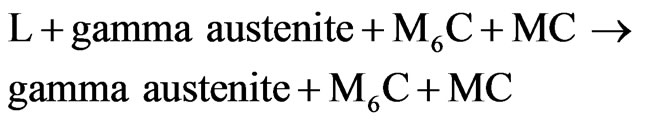
Four of the TC sections calculated in this work—corresponding to the alloy 6-5-2 and its three silicon variants 6-5-2-1, 6-5-2-3 and 6-5-2-5 (Table 2)—are shown in Figure 1. They illustrate the influence of the carbon and silicon content on the stability of the phases. The left corner of each section represents an alloy of Fe and Cr with W, Mo, V, and Si in the ratio as they are in the basis alloy (6:5:2:0; 6:5:2:1, 6:5:2:3 and 6:5:2:5, respectively), and this ratio is kept constant while the C content increases to the right. The tie-lines are not in the section plane and, therefore, the amount and composition of the phases must be calculated separately. The CALPHAD method has been successfully used for computation of phase equilibrium the multi-component high speed tool steel system [9,10,13]. Calculated multi-component phase diagrams and property diagrams for steels are as accurate as a measured diagram, and much faster to obtain.
 (a)
(a)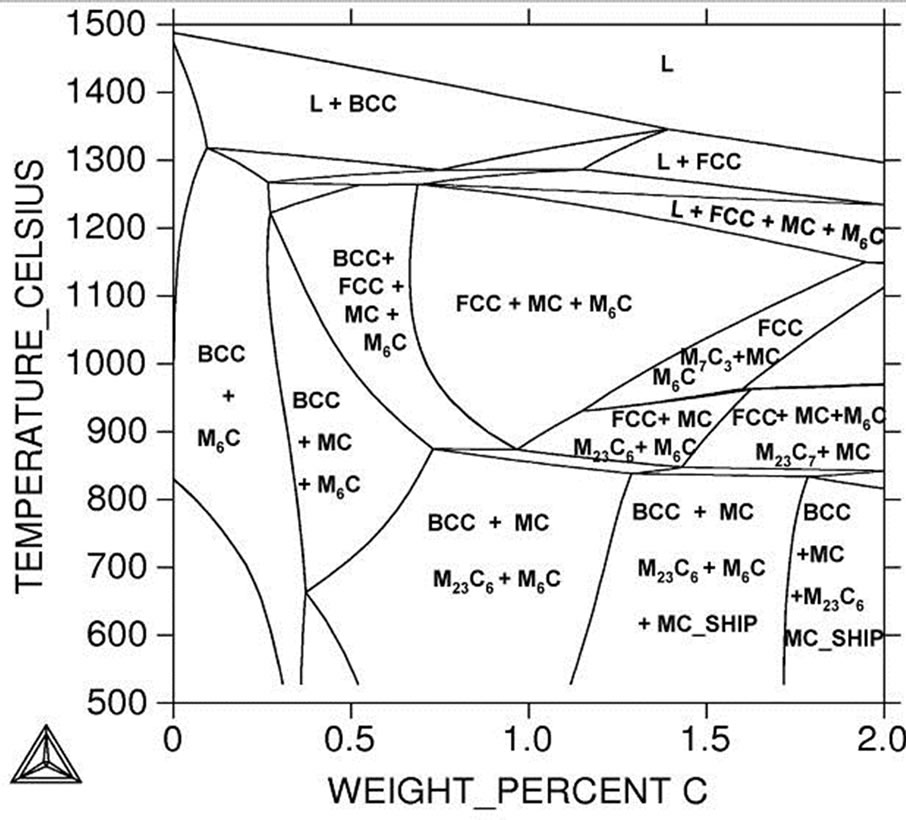 (b)
(b) (c)
(c)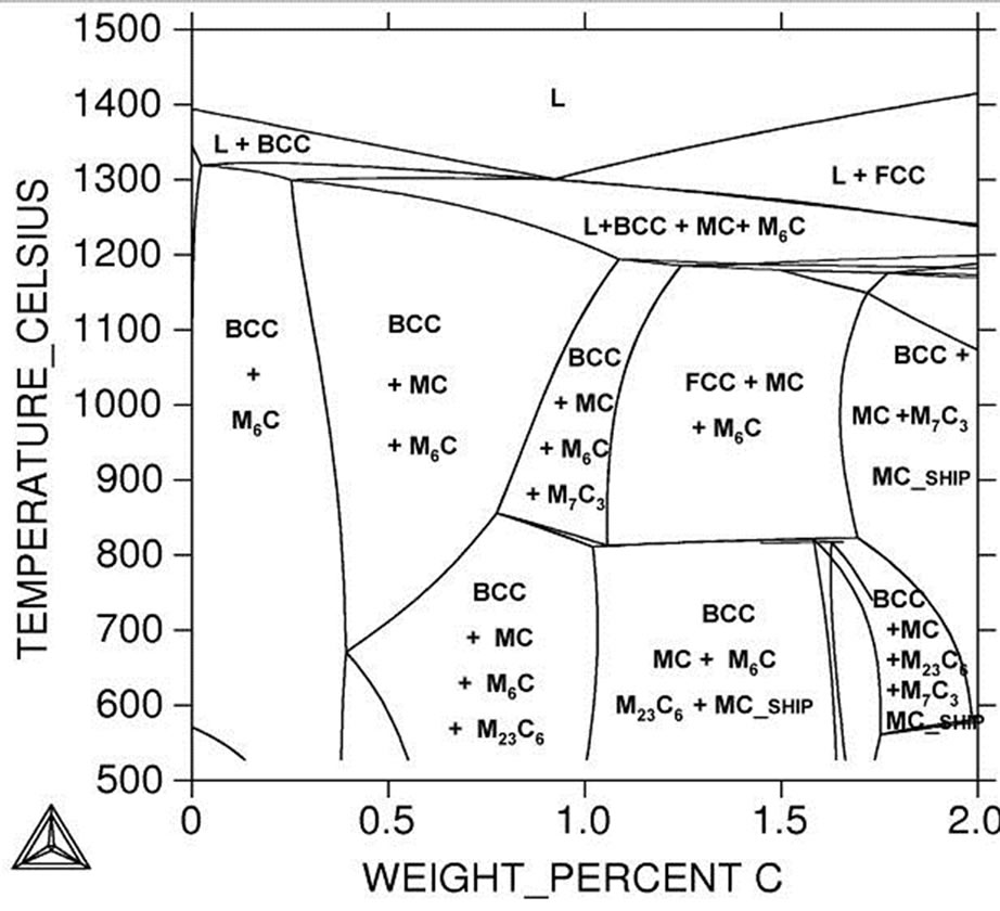 (d)
(d)
Figure 1. (a) through (d) temperature-concentration (TC) sections for standard HSS, AISI M2 and its silicon variants. (a) Standard M2; (b) 1% Si; (c) 3% Si; (d) 5% Si.
The diagrams calculated below are for the tool steel with Fe-Cr-W-Mo-Si-V-C. Figure 1 is an isopleth phase diagram with fixed alloy content except C and Fe, Figure 2 is a phase fraction diagram for a the same alloy with fixed carbon content. In Figure 1, one can recognize the usual phase fields that a high-speed steel alloy passes through as it is cooled from the liquid state. The solidification sequence of the investigated steels is complex and involves several reactions between the solid and the liquid phases, which may lead to particular microstructural characteristics, depending on the exact composition of the alloy and on the cooling rate. Because the isopleths phases diagrams for investigated steels show equilibrium phase relations, kinetic segregation effects and their consequences such as the formation of M2C are not predicted by them.
3.2. Solidification Reactions of Silicon Containing AISI M2 High Speed Tool Steel
3.2.1. For Standard High Speed Tool Steel, AISI M2
In general, in Figure 3(a) at the beginning of the cooling stage the delta-ferrite solidifies first from the melt in the form of primary dendrites, according to the reaction (1), beginning at around 1435˚C.
 (1)
(1)
As the separation of delta ferrite proceeds, the carbon content increases in the melt; solidification continues as a peritectic reaction. Transformation delta ferrite to austen-
 (a)
(a) (b)
(b)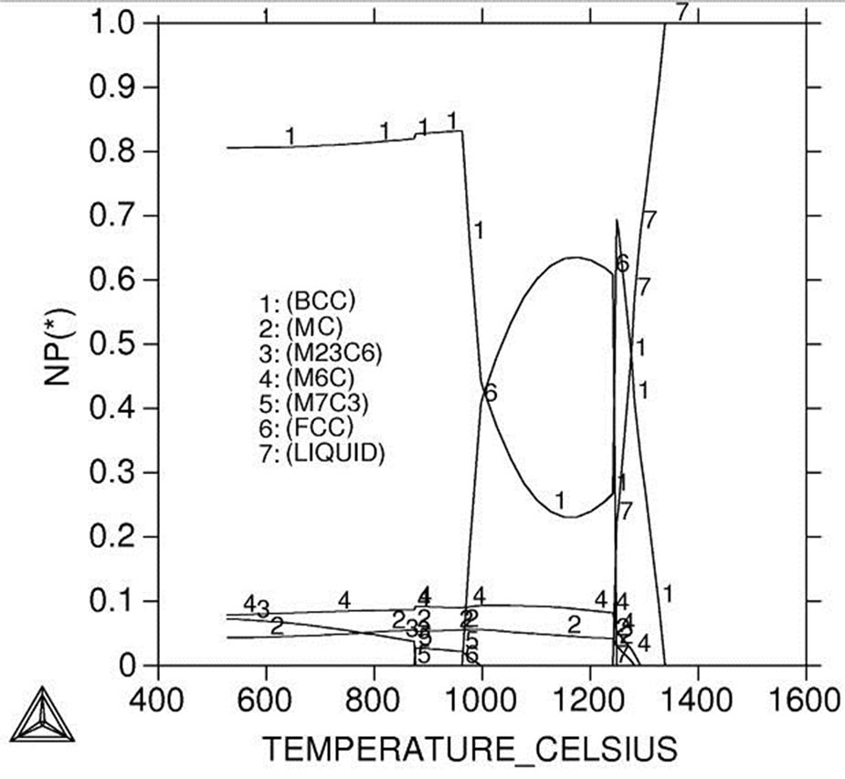 (c)
(c)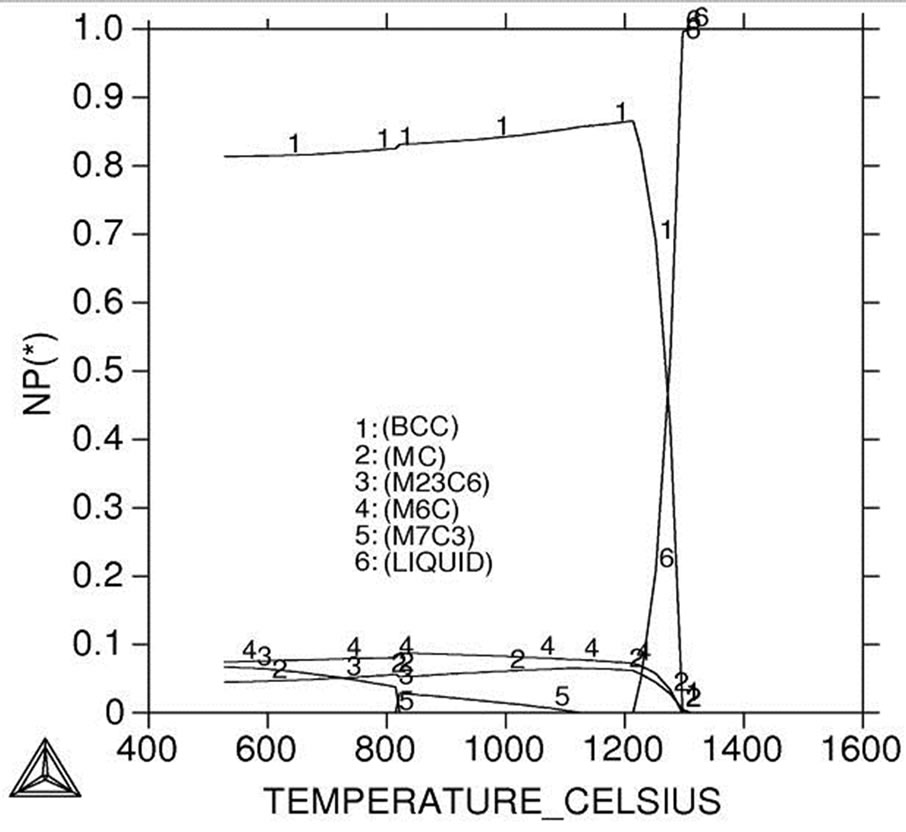 (d)
(d)
Figure 2. Temperature dependence of the amounts of phases for standard HSS, AISI M2 and its silicon variants. See Table 1 for details. (a) Standard M2; (b) 1% Si; (c) 3% Si; (d) 5% Si.
 (a)
(a)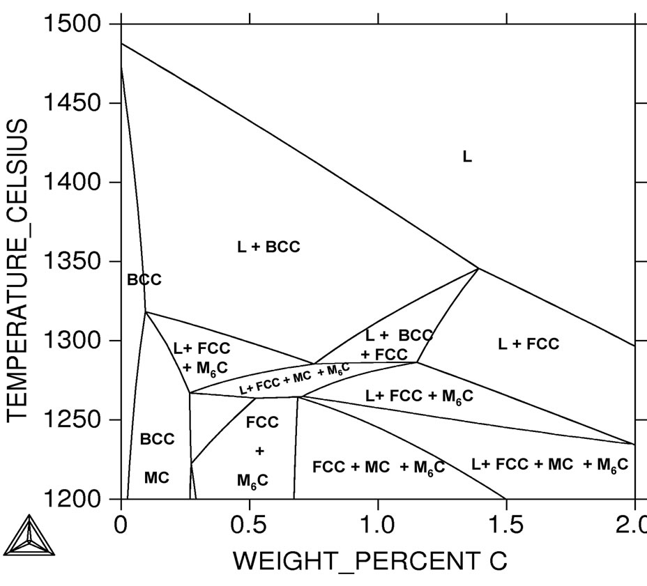 (b)
(b)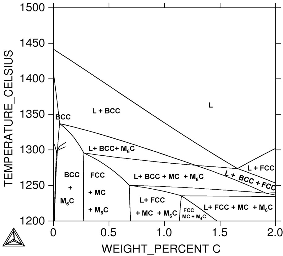 (c)
(c)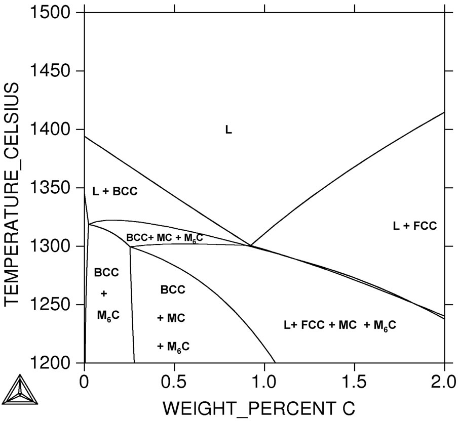 (d)
(d)
Figure 3. Magnification of the transformation zone in Figure 1. (a) Standard M2; (b) 1% Si; (c) 3% Si; (d) 5% Si.
ite, according to:
 (2)
(2)
When the liquid is leaving point B, ferrite should normally be completely transformed. Then the un-solidified melt follows the eutectic reaction, producing austenite plus carbides, as shown in Equation (3).
 (3)
(3)
As we mentioned previously, two kinds of carbide are present in the eutectic. Globular carbides, identified as M6C carbides, are grown in the interdendritic eutectic in contact with the austenite dendrites, as it may be anticipated from reaction (3).
The MC carbides nucleate on them and grow in a further stage closing the solidification sequence at point C by the eutectic decomposition of the last remaining liquid. As a matter of fact, the morphology of the M6C particles and their location suggests that they have solidified before MC. The above observations stating that the M6C solidifies before MC. In our work, we can state that, the MC solidifies from the residual liquid at around 1230˚C. However the MC carbides predominate in the eutectic and their formation in expense of the M6C carbides is justified, because MC is favored from a relatively high carbon and vanadium content in the melt.
3.2.2. For Silicon Content (1% Si)
Figure 3(b) shows that, for silicon containing high speed tool steel reaction (3) may be changed due to effect of silicon on transformation temperature to the following reactions in sequence:
 (3)
(3)
It well known that, silicon is one of strong ferrite stabilizer element and the presence of silicon leads to precipitate M6C instead of MC in silicon free high speed steel. We can reported that, M6C carbide precipitate first at the grain boundary of austenite which deplete the carbon and increase the alloying elements in the adjacent liquid. From the previous, precipitation of MC carbide was precipitate according to the following reaction:
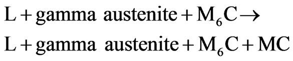 (4)
(4)
By continues cooling of the investigated steels the reaction leads to increase the size and volume of the MC carbides.
 (5)
(5)
We can concluded that silicon containing high speed tool steel after solidification include austenite with two different kind of carbides (MC + M6C).
3.2.3. For Higher Silicon Content (3% Si)
For higher silicon content (3% Si), as we mentioned before with increasing the silicon content leads to M6C carbide precipitate from the liquid but the rest is same, as shown in Figure 3(c). M6C carbides pins the austenite grains to grow then the structure is very fine at the solidification end. During solidification process, different carbides with different chemical composition were precipitated above the M6C carbides. So, we can expect that the precipitated carbide grow very much and the chemical composition changes along the carbide.
3.2.4. The Effect of Higher Silicon
The effect of higher silicon contents can be understood with the help of Figure 3(d), where a TC section based on an alloy with 5 mass pct Si is depicted. It can be seen that MC should be the first phase to solidify, directly from the liquid, preceding the crystallization of delta ferrite. This was taken to indicate that the MC had begun to crystallize long before the delta ferrite, giving it enough time to grow in the liquid without disturbance.
With higher carbon content, the solidification path tends to change from primary formation of delta ferrite to austenite, and the liquidus temperature decreases, in agreement with the literature [14-16]. Actually, Figure 3(a) shows that increased carbon content had three obvious effects on the AISI M2 concentration—temperature diagram. It depressed the liquidus and solidus but raised the peritectic, thus narrowing and eventually eliminating the gap between the liquidus and the peritectic at high carbon contents which caused primary crystallization of austenite at > 1.38 wt pct C for standard AISI M2 (0.4% Si) but this critical value of carbon was effected by the additions of silicon, Figure 3.
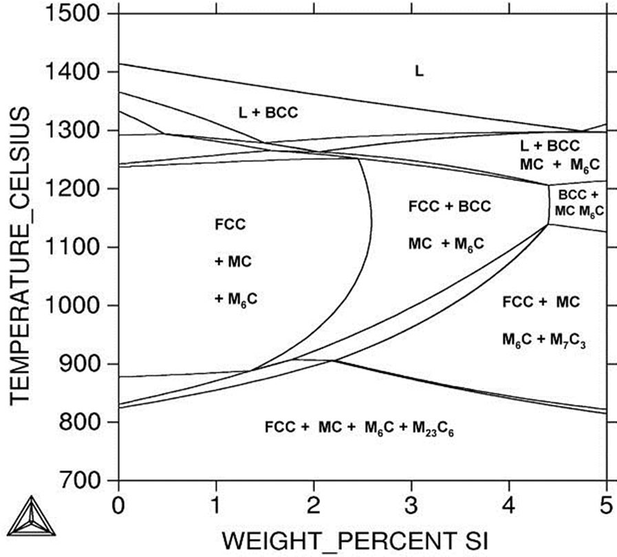
A better view of the influence of silicon on investigated steels is provided in Figure 4, where TC section is shown together with an enlargement of Figure 3(b). The addition of silicon to M2 steel promotes ferrite formation instead of the austenite-stabilizing effect of carbon. Analysis of Figure 4 shows that the liquidus and solidus temperatures were only slightly affected by small or moderate increases in the nominal silicon content, but the peritectic was strongly depressed. This widens the gap between the liquidus and the peritectic, since the crystal-
 (a)
(a) (b)
(b)
Figure 4. (a) Temperature-concentration (TC) section based on chemical composition of AISI M2 steel. (b) Magnification of the transformation zone in (a).
lization of a greater volume fraction of ferrite is now required before the remaining melt becomes sufficiently enriched in carbon to trigger the austenite reaction. On the other hand, increase silicon contents cause a strong stabilization of the M6C carbide. Already at low silicon concentrations, the M6C-eutectic transformation occurs at a higher temperature than that of the MC.
3.3. Transformation Temperatures and Amounts of Phases
Many DTA measurements have been reported for HSS 6-5-2 [17] with which we can compare the results of the calculations. Unfortunately, because of kinetic effects accompanying solidification, not all of them can be associated with a transformation that would occur in equilibrium. For example, segregation and incomplete peritectic reactions lead to different transformation sequences and thus to different transformation temperatures. Usually, measurements of the liquidus temperatures are the most reliable ones, but they are not always available. Also usually not available are solid-state reaction temperatures, such as the alpha-ferrite to austenite transformation, which could serve for comparisons in the low-temperature region. Table 4 shows the measured liquidus and solidus temperatures together with the calculated values for the investigated steels listed in Table 3. The calculated values are consistently in good agreement with the measurements of Reference [17]. The calculated and measured amounts of phases for a Si-containing HSS 6-5-2 alloy are given in Table 5. A good agreement is also observed here.
3.4. Composition of the Carbides and Matrix
It well known that, the microstructures in as-cast highspeed steels may take several morphologies and consist of various alloy carbides, depending on steel composition and solidification conditions. The primary alloy carbide in high-speed steels is M6C, where M, the metal component, may consist of tungsten, molybdenum, and iron. Vanadium is typically present in MC carbides, and tungsten and molybdenum may be present in M2C carbides.
Figure 5 shows, as an example, the variation of composition with temperature for the carbide M6C in the alloy 6-5-2-1 Si. According to the calculations, this carbide should crystallize at 1286˚C, and should continue in contact with the melt down to 1246˚C. Below this, only solid phases should be found. Since the austenitization treatment of this steel is performed at about 1230˚C, it should produce a state close to the thermodynamic equilibrium. Therefore, the compositions of the carbides after austenitization (and quenching and tempering, which causes no further changes in the blocky carbides) may be used here as a legitimate basis for comparison. The calculated phase compositions and the measured values are presented
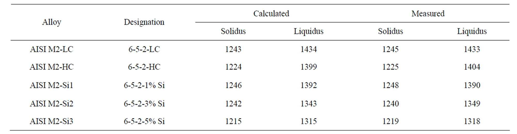
Table 4. Calculated and measured liquidus and solidus temperature at the AISI M2 and its three silicon variants.
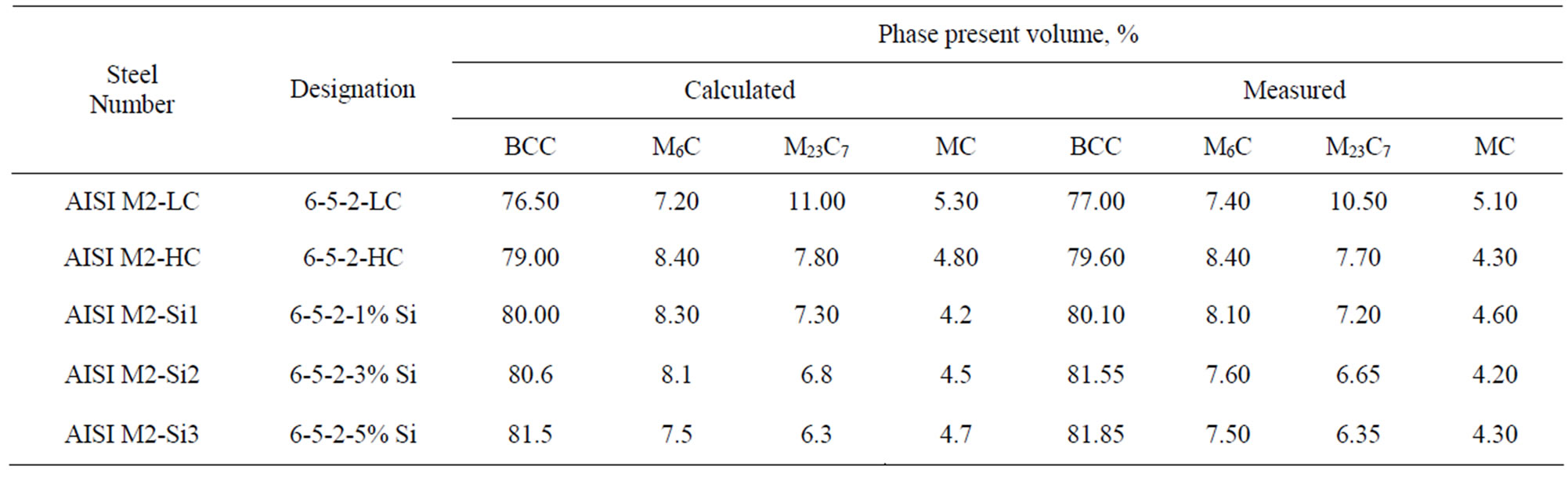
Table 5. Calculated and measured [18] amount of phases in an investigated high speed tool steel given in mole percent.
in Table 6 for the M6C carbide, in Table 7 for MC, in Table 8 for M23C6 and in Table 9 for the matrix.
M6C: a tungstenor molybdenum-rich carbide corresponding to the complex FCC carbide of the composition range Fe3W3C to Fe4W2 C in tungsten steels, or Fe3Mo3C to Fe4Mo2C in molybdenum steels, and capable of dissolving some chromium, vanadium, and cobalt. The obtained results show that, agreement between calculated and measured values is good for all the elements, when the experimental scatter is taken into account. From the result of Table 6, addition of silicon increase tungsten and molybdenum in the precipitated carbides. From previous results we can conclude that, addition of silicon to investigated steels promotes the formation of M6C type carbides. Consonant with the measurements, silicon is not found in this carbide in any of the HSS-Si.
MC: a vanadium-rich carbide corresponding to the FCC carbide of composition range VC to V4C3 and capable of dissolving limited amounts of tungsten, molybdenum, chromium, and iron. Table 7 shows that introduction of silicon to investigated steels leads to increase content of dissolving elements in such carbides for example Cr, Mo, W and Fe. In addition, Table 7 shows that the precipitate carbide contains lower carbon content than
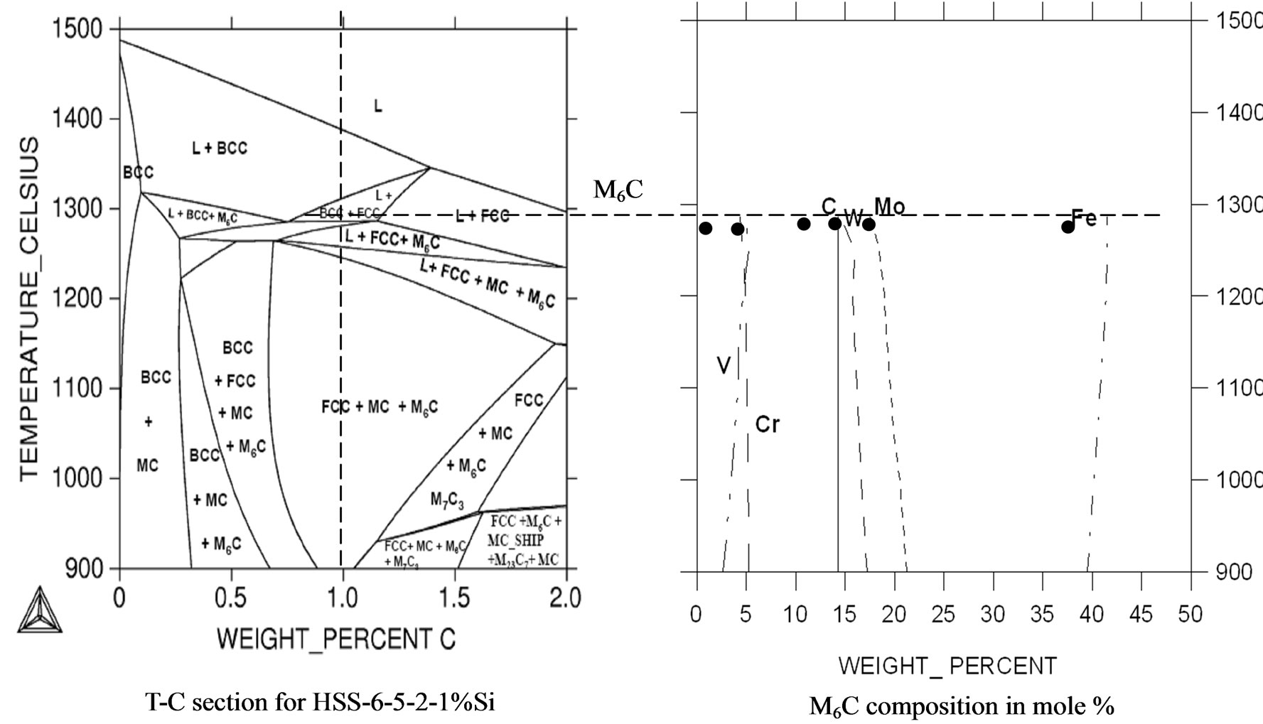
Figure 5. Calculated and measured [16] M6C composition in alloy 6-5-2-1 Si.
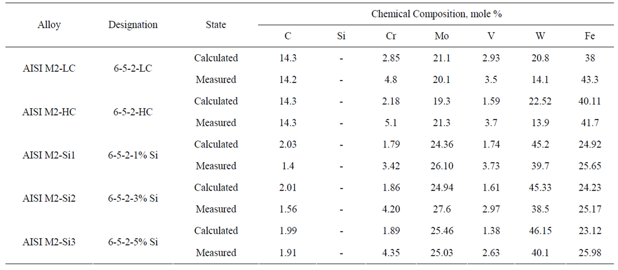
Table 6. Calculate and measured composition of the M6C carbides.

Table 7. Calculate and measured composition of the MC carbides.

Table 8. Calculate and measured composition of the M23C6 carbides.
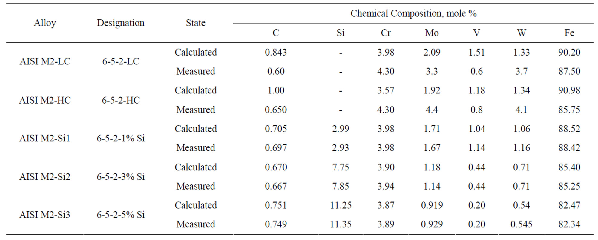
Table 9. Calculate and measured composition of the matrix.
standard AISI M2 steel.
M23C6: a chromium-rich carbide corresponding to the FCC carbide Cr23C6 and capable of dissolving iron, tungsten, molybdenum, and vanadium. Table 8 shows that the chemical composition of calculated and measured M23C6 carbides. From the result of this, Table 8 increases silicon content leads to dissolve more chromium, vanadium and tungsten on comparable with standard value in high speed tool steel AISI M2. Table 8 also shows that the decrease in the carbon content of silicon containing high speed AISI M2 steels.
Matrix: The composition of the matrix is of great importance, because it determines the starting state for the precipitation of the secondary carbides [19]. Table 9 shows the calculated and measured values for some alloys. The concordance here is also good.
The matrix of the investigated steel contains the lowest content of vanadium, molybdenum and tungsten because most of this elements soluble in carbides. It well known that silicon is ferrite stabilizer and ensure the formation of carbides with high alloying content but with less carbon, Table 9.
We can expect that after full heat treatment (hardening-tempering) of investigated steels, the matrix of the investigated steel will contain the highest content of vanadium, tungsten because the M23C6 and M6C carbides in this steel, even enriched with vanadium and tungsten is less stable during heating and more soluble in the austenite than the vanadium-base MC carbide. But to be sure about this exception it needs more work and effort.
3.5. Effect of Alloying Elements
The composition of the most studied and the best known high-speed steel AISI M2 has been chiefly developed about 100 years ago as a result of the determination of the cutting properties of tools produced from numerous heats in which the concentration of carbon, tungsten, chromium, molybdenum, vanadium and other alloying components was varied in narrow ranges. The steel contained about 1% C, 6.65% W, 4% Cr, 5% Mo and 2% V and had a quite high hardness of up to 62 HRC.
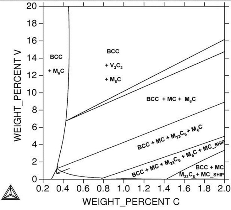
Figure 6 presents a part of the phase diagram of alloys of the Fe-V-C system; it is shown that the introduction of
 (a)
(a)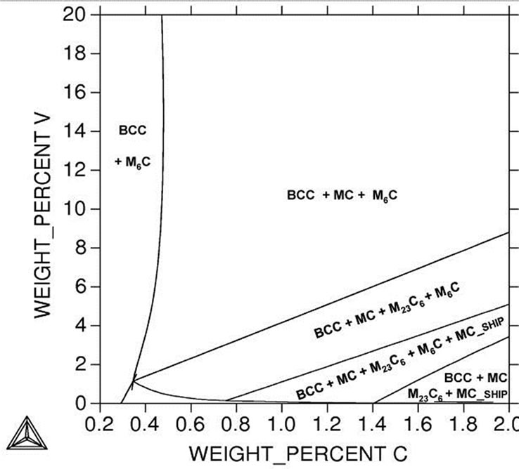 (b)
(b)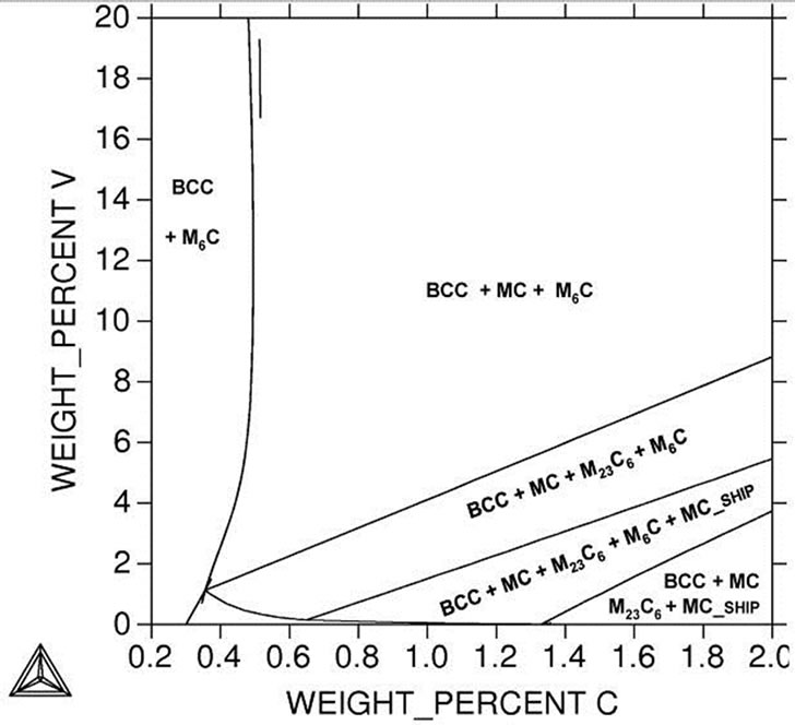 (c)
(c)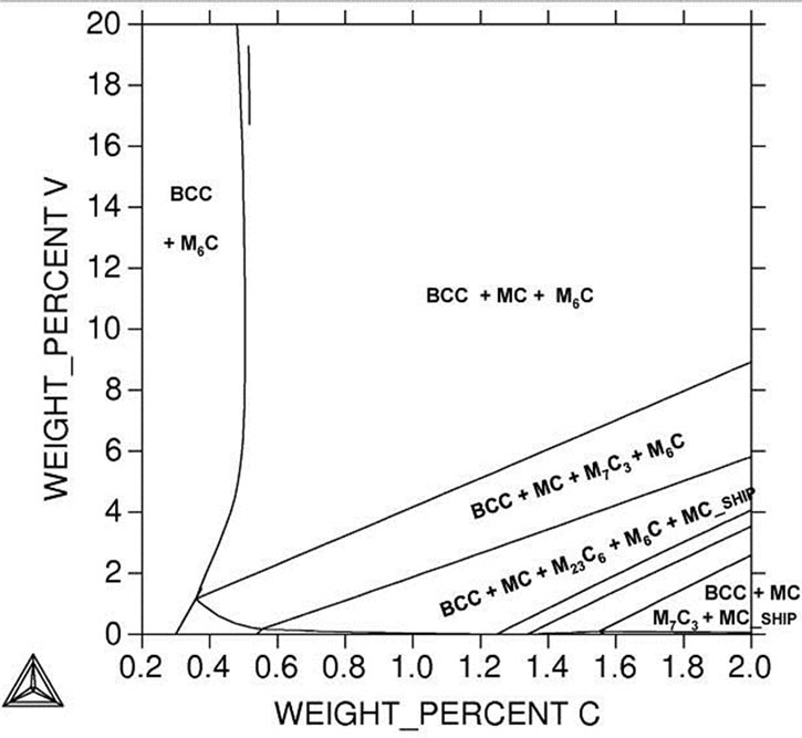 (d)
(d)
Figure 6. Portion of the 727˚C (1000˚ K) isothermal section of the Fe-V-C system with compositions of investigated steels indicated. (a) Standard M2; (b) 1% Si; (c) 3% Si; (d) 5% Si.
 (a)
(a)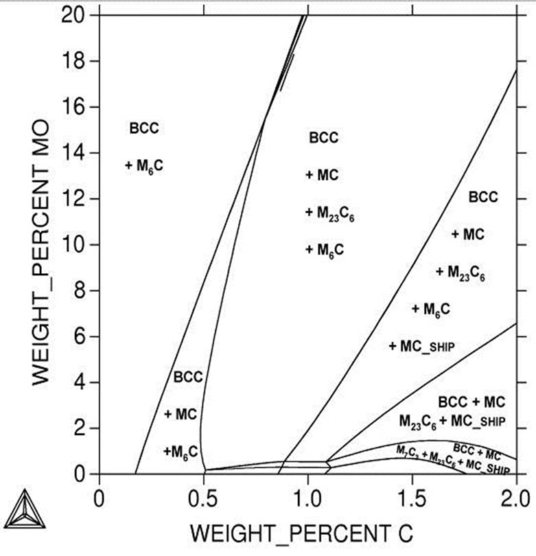 (b)
(b) (c)
(c) (d)
(d)
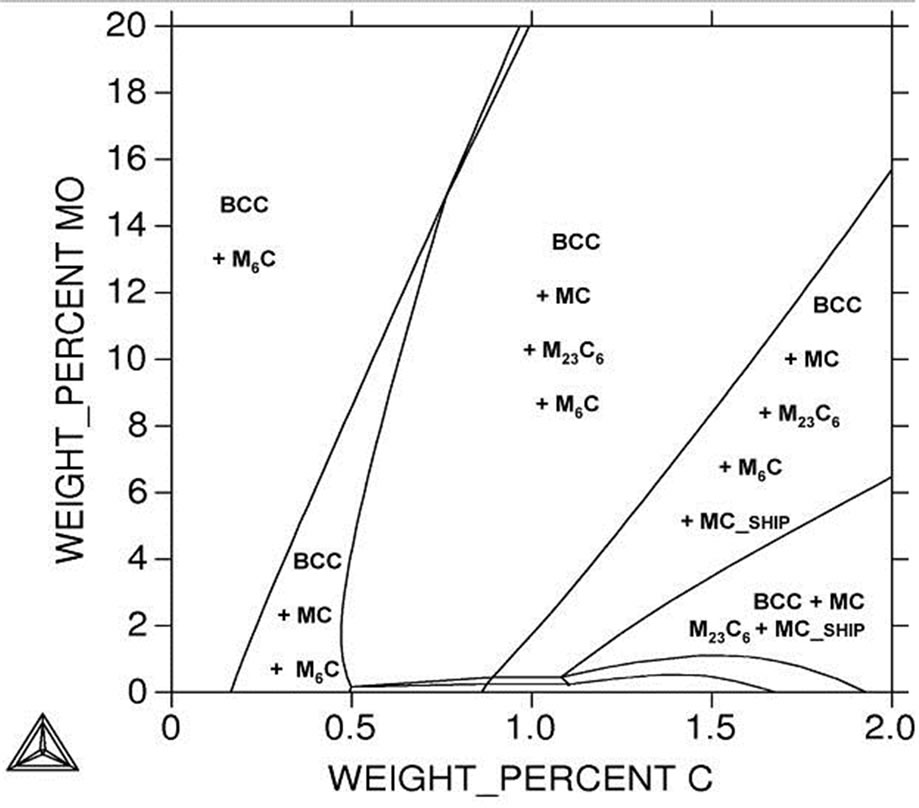
Figure 7. Portion of the 727˚C (1000˚ K) isothermal section of the Fe-Mo-C system with compositions of investigated steels indicated. (a) Standard M2; (b) 1% Si; (c) 3% Si; (d) 5% Si.
silicon into the alloy has a great effect on the carbides precipitate. This figure shows that increase silicon promotes the formation of MC and M6C type carbides. In additions, decrease in vanadium content or increase in the concentration of carbon in the alloy causes the appearance of M23C6 or M7C3 carbides according to the silicon content.
Figure 7 presents a part of the phase diagram of alloys of the Fe-Mo-C system, from which we can infer that the mentioned content of molybdenum (5%) and carbon (1%) corresponds to an alloy the carbide phases of which are represented by an MC + M6C + M23C6 carbides. Increase in the content of silicon in the alloy causes the appearance of MC_ship carbides. On the other hand, for more silicon content 5% Si, the alloy carbide corresponds to purely MC + M7C3. Decrease in molybdenum or increase the carbon content leads to precipitate M7C3 and/or M3C2 according to the wt % of both Mo and C.
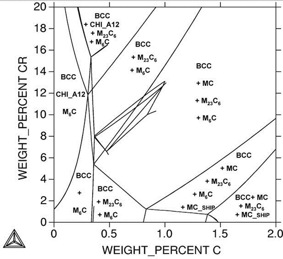
Figure 8 presents a part of the phase diagram of alloys of the Fe-Cr-C system, from which we can infer that the mentioned content of chromium (4%) and carbon (1%) corresponds to an alloy the carbide phases of which are represented by an MC + M6C + M23C6 carbides. In the case of silicon 1% to 3%, decrease in the content of chromium and increase carbon content in the alloy causes the appearance of MC_ship carbides. On the other hand, for more silicon content 5% Si, the alloy carbides correspond to purely MC + M7C3. Decrease in chromium or increase the carbon content leads to precipitate MC_ship. So on all content of silicon decrease in chromium and increase in carbon content promotes the formation of MC_ship carbides.
 (a)
(a)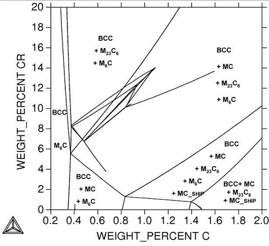 (b)
(b)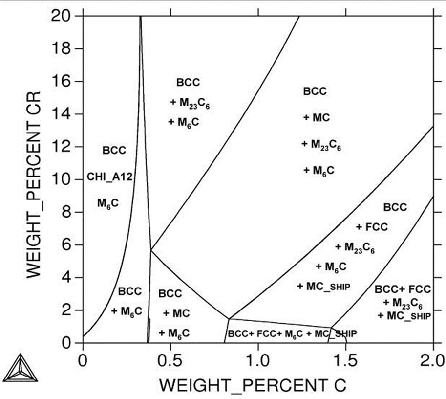 (c)
(c)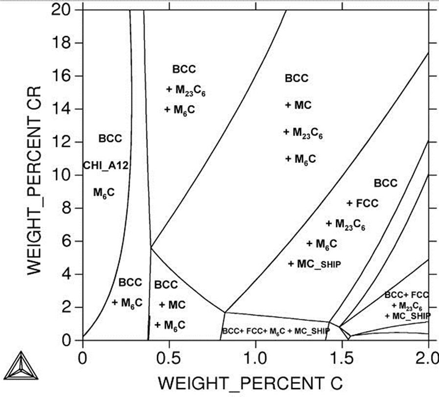 (d)
(d)
Figure 8. Portion of the 727˚C (100˚ K) isothermal section of the Fe-Cr-C system with compositions of investigated steels indicated. (a) Standard M2; (b) 1% Si; (c) 3% Si; (d) 5% Si.
It was shown in these Figures 6-8 addition of silicon above 3% Si promotes the presence of M7C3 instead of M23C6 and MC carbides.
The introduction of chromium (about 4%) into the investigated steel causes formation of a low amount of ironand chromium base carbides with composition M23C6 carbide.
4. Conclusions
In the present work, some temperature-concentration diagrams for silicon modified AISI M2 steel are presented by calculated quantities (melting and transformation temperatures, amount and compositions of phases). Calculated data are compared with standard AISI M2 high speed tool steel. The following conclusion can be drawn:
1) The thermodynamic calculations of phase equilibria in silicon-containing high-speed steels give results that are in good agreement with experimental observations on solidification paths, and amounts and compositions of phases. Interpretations of special solidification features which were up to now only hypothetical, have been confirmed by the calculation.
2) The total volume fraction of the silicon containing steel carbides is quite close to standard steel AISI M2. Increase in silicon promotes the formation of MC and M6C type carbides. In additions, decrease in vanadium content or increase in the concentration of carbon in the alloy causes the appearance of M23C6 or M7C3 carbides according to the silicon content.
3) The tungsten content of the M6C carbides in silicon steels is higher than standard steel AISI M2. Growth in the concentration of tungsten in these carbides increases only the mass fraction of these carbides but the volume of these carbides virtually equal.
4) The introduction of silicon into the metal causes formation of a low amount of ironand chromium base carbides (M23C6) with composition higher chromium content and dissolution of chromium in the M6C carbide.
5) The introduction of silicon into the metal causes formation of MC with largest amount of vanadium and tungsten.
6) Calculations and measurements of phase and carbides confirm that silicon dissolved only in the matrix and totally absence on the carbides but addition of silicon encourage for precipitate carbides with higher alloying element contents.
REFERENCES
- A. P. Gulyaev, “Properties and Heat Treatment of HighSpeed Steel [in Russian],” Mashgiz, Moscow, 1939.
- N. A. Minkevich, “Low-Alloy High-Speed Steels [in Russian],” Metallurgiya, Moscow, 1944.
- Yu. A. Geller, “Tool Steels [in Russian],” Metallurgiya, Moscow, 1983.
- E. C. Bain and H. W. Paxton, “Alloying Elements in Steel,” 2nd Edition, ASM, Metals Park, Ohio, 1966, pp. 123-162, 243-247.
- M. A. Bayer and A. B. Brucer and V. Teledyne, “High Speed Tool Steels,” ASM Handbook, Vol. 16, Machining ASM Handbook Committee, 1989, pp. 51-59.
- Y. Geller, “Tool Steels,” Mir Publishers, Moscow, 1978.
- E. Pippels, J. Woltersdorf, G. Pöckl and G. Lichtenegger, “Microstructure and Nano-Chemistry of Carbide Precipitates in High-Speed Steel S 6-5-2-5,” Materials Characterization, Vol. 43, No. 1, 1999, pp. 41-55. doi:10.1016/S1044-5803(99)00003-0
- P. Fusheng, H. Mitsuji, L. Yun, D. Peidao, T. Aitao and D. V. Edmonds, “Carbides in High-Speed Steels Containing Silicon,” Metallurgical and Materials Transactions A, Vol. 35A, No. 9, 2004, pp. 27-57.
- B. Sundman and J. Ågren, “A Regular Solution Model for Phases with Several Components and Sublattices, Suitable for Computer Applications,” Journal of Physics and Chemistry of Solids, Vol. 42, No. 4, 1981, pp. 297-301. doi:10.1016/0022-3697(81)90144-X
- H. Halfa, “Characterization of Electroslag Remelted Super Hard High Speed Tool Steel Containing Niobium,” Steel Research International, Vol. 84, No. 5, 2013, pp. 495-510. doi:10.1002/srin.201200332
- G. F. Vander Voort, “Metallography: Principles and Practice,” McGraw-Hill, New York, 1984.
- G. Hoyle, “High Speed Steels,” Butterworths, London, 1988.
- G. C. Coelho, J. A. Golczewski and H. F. Fischmeister, “Thermodynamic Calculations for Nb-Containing HighSpeed Steels and White-Cast-Iron Alloys,” Metallurgical and Materials Transactions A, Vol. 34A, No. 9, 2003, p. 1749.
- H. Fredriksson and S. Brising, “The Formation of Carbides during Solidification of High-Speed Steels,” Scandinavian Journal of Metallurgy, Vol. 5, No. 4, 1976, pp. 268-275.
- R. Riedl and H. Fischmeister, “Gerichtete Erstarrung: Eine Methodezur Erforschung des Kristallisationsablaufesbei Stählen,” Bergund Hüttenmännische Monatshefte, Vol. 129, No. 2, 1984, pp. 131-135.
- R. Riedl, S. Karagöz, H. Fischmeister and F. Jeglitsch, “Developments in High-Speed Tool Steels,” Steel Research International, Vol. 58, No. 3, 1989, pp. 339-352.
- H. F. Fischmeister, R. Riedl and S. Karagöz, “Solidification of High-Speed Tool Steels,” Metallurgical and Materials Transactions A, Vol. 20A, No. 10, 1989, pp. 2133- 2148.
- S. Karagöz, I. Liem, E. Bischoff and H. F. Fischmeister, “Determination of Carbide and Matrix Compositions in High-Speed Steels by Analytical Electron Microscopy,” Metallurgical and Materials Transactions A, Vol. 20A, No. 12, 1989, pp. 2695-2701.
- S. Karagöz and H. F. Fischmeister, “Cutting Performance and Microstructure of High Speed Steels: Contributions of Matrix Strengthening and Undissolved Carbides,” Metallurgical and Materials Transactions A, Vol. 29, No. 1, 1998, pp. 205-216. doi:10.1007/s11661-998-0173-3