Open Journal of Applied Sciences
Vol.3 No.2(2013), Article ID:33388,8 pages DOI:10.4236/ojapps.2013.32030
Assessment of the Direct Sun-Light on Rural Road Network through Solar Radiation Analysis Using GIS
Department of Geography, Harokopio University, Athens, Greece
Email: xalkias@hua.gr, afaka@hua.gr, kalogeropoulos@hua.gr
Copyright © 2013 Christos Chalkias et al. This is an open access article distributed under the Creative Commons Attribution License, which permits unrestricted use, distribution, and reproduction in any medium, provided the original work is properly cited.
Received January 31, 2013; revised March 2, 2013; accepted March 11, 2013
Keywords: GIS; Direct Sunlight Exposure; Solar Radiation; Spatiotemporal Analysis
ABSTRACT
The movement of vehicles on the roads, during summer, can sometimes hide risks involved in direct sunlight. In places where the relief is complicated, road network usually consists of a road complexity. This complexity in conjunction with the motion of a vehicle on a road and the position of the sun at the same time may result in the loss of vision in some sections of the road. This paper describes a GIS-based methodology of the spatiotemporal analysis of this phenomenon. Thus, for a given study area, in this case of Milos Island, Greece, the geometry of the road network, the terrain morphology and the solar radiation (in specific time intervals during summer) have been analyzed. The result of this procedure is a map illustrating the sections of the road where direct sunlight includes a serious amount of risk for the drivers. Applying this methodology for long periods of time may lead to prevention policies adoption related to accidents of direct exposure to sunlight. Moreover, this methodology could be an additional module in car navigation systems.
1. Introduction
Solar radiation is made up of electromagnetic waves which travel from the sun to the earth with the speed of light. The quantity of short wave radiant energy emitted by the sun passing through a unit horizontal area in unit time is referred generally as global solar radiation. This incoming solar radiation is modified as it travels through the atmosphere and again once it hits the surface. So the three main components of solar radiation are the direct, the diffused and the reflected solar radiation (Figure 1).
Direct radiation is intercepted unimpeded, in a direct line from the sun. Diffuse radiation is scattered by atmospheric constituents, such as clouds and dust. Reflected radiation is reflected from surface features [1].
This global solar radiation can be used in predictions of various phenomena. Thus, solar radiation modeling can be a useful tool for the design of building energy systems, solar energy systems and a good estimate of the thermal environment within buildings [2,3]. Furthermore, solar radiation modeling can be used in Earth Sciences as a climatic element and as a key in biological processes [4] in the field of agriculture and forestry [5]. In this current work, solar radiation is computed within ArcGIS environment using the corresponding tool (The Solar Radiation Tool of the Spatial Analyst Tools). The solar radiation tools can perform calculations for a specific point or for a given surface (e.g. for a DEM) within ArcGIS.
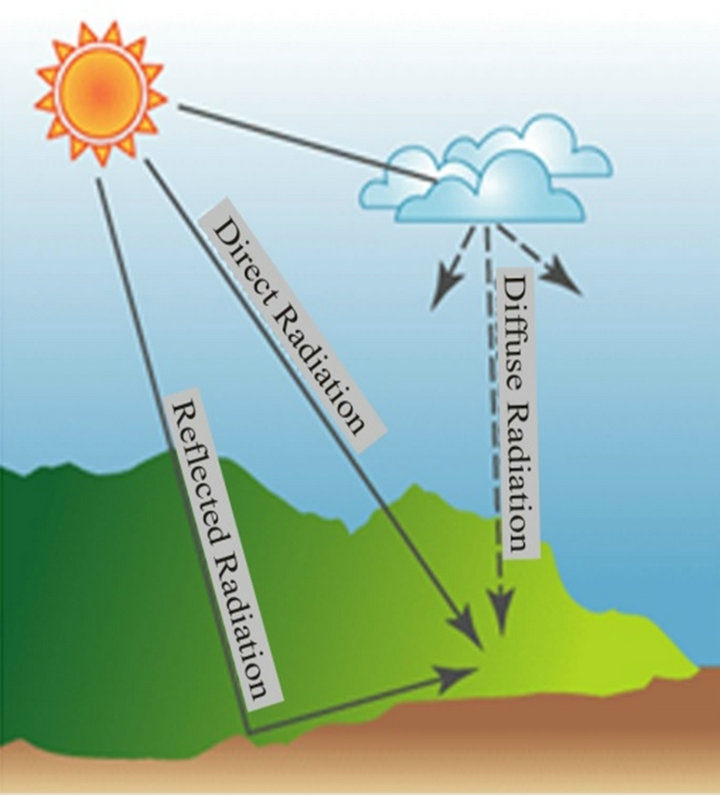
Figure 1. The three main components of solar radiation [1].
It is generally accepted that the use of GIS can be a very valuable tool in modeling various phenomena. GIS incorporates all the available material that technology offers. So hardware, software and databases are combined towards the extraction of new knowledge. They give the possibility to have fast results throughout the process, which extends from the data management to the analysis and the visualization of them [2]. This is a technology that is constantly evolving and which enables users to edit high volume of data. It is also a technology that provides the ability to analyze complex spatiotemporal phenomena.
Most scientists now have adopted GIS to analyze and visualize the derived results. Thus, there are a lot of developed applications for sciences such as business, education, natural resources and natural disasters, mapping, health services, public safety, transportation, urban planning, built of environment (environmental engineering), forestry, agriculture etc [3,6-8].
Thus, GIS offers the ability for applications in many different fields of science such as urban planning, hydrology, archeology, epidemiology, monitoring changes in land use, etc. [9-12]. This technology provides the necessary facilities to the users in order to perform various simulations towards having quick and reliable results. These results may be a key element for solving complex spatial problems and a decision tool for policy makers. At the same time, a GIS based spatial decision support system (SDSS) is a powerful modeling framework for decision makers in order to analyze and simulate various spatial phenomena [13,14].
GIS is also a technology that provides well-organized possibilities for the analysis of phenomena which are variable in space and time. In this current work, an aspect of road accident risk is evaluated in terms of the exposure to direct sunlight. This is a spatiotemporal phenomenon due to the continuous change of the position of the sun and the motion of a vehicle on a road. Road risk accident analysis may concern the study of accidents that had already occurred in an area and the study of risk factors which can be directly related to the occurrence of accidents [15-17]. Actually, this is part of the public health approach. This approach is not only helpful in the analysis of a specific risk factor in transportations, but also provides a framework for decision-making throughout its entire process, from identifying a problem to implementing an intervention [18-20].
Moreover, road risk analysis can identify high crash zones either between vehicles or in accidents which involve pedestrians [21]. A potential outcome of the proposed analysis is the prevention of accidents in rural road network. Therefore, risk analysis can be followed during a road network planning by considering spatial and thematic data [22].
In this study, GIS is used in order to simulate the exposure to direct sun light in a rural road network. The main goal was to provide a system which can identify the parts of the road that are in risk for a specific time period due to direct sunlight. When a vehicle is moving towards the direction of the sun and at the same time the sun altitude is low in comparison with road gradient, drivers may experience temporary visual defects which are a common accident triggering factor [23].
The phenomenon of the exposure to direct sunlight on a road segment is not static. The position of the sun and the moving vehicle are changing from time to time and from space to space. Thus, this exposure is a spatiotemporal phenomenon and should be handled accordingly [24].
To the best of our knowledge, there are many studies that use GIS in road risk assessment. However, studies related to the proposed analysis or similar analyzes [25] are limited. The main part of these studies explore the frequency of occurrence of accidents based on specific factors [26], while others use GIS as a tool for visualization of accident data and analysis of hot spots in highways [27,28].
The first part of this work refers to the physical process of the sun movement through the estimation of solar radiation for a specific time in the study area. Next, this is applied on the spatial data structures (DEM and road network) in order to isolate the road segments that are in risk due to the exposure to direct sunlight.
2. Data
In order to conduct the modeling a set of initial data was necessary. The original data used in this work can be divided into two main categories.
2.1. Spatial Data
The essential needed data for this current methodology is a Digital Elevation Model (DEM) of the study area. The presence of a full DEM would be the ideal case for the analysis. That is a 3D model in which the buildings within urban areas, the artificial barriers (e.g. bridges) and the trees next to the roads will appear in the correct position and with the correct geometry characteristics. The lack of this ideal situation led to the adoption of a model that is easier to manufacture. For the purpose of this work a Digital Terrain Model (DTM) was created within ArcGIS 9.3 environment using the ANUDEM algorithm [29,30]. This DTM was derived from the digitization of contour lines (contour line interval: 20 m), elevation/trigonometric points and the stream network (the source of the topographic maps was the Hellenic Military Geographical Service-HMGS). The result of this procedure was a 3D terrain model of 20 × 20 m spatial resolution.
To conduct the analysis at road segment level, it was necessary to import a route from the road network of the study area. The layer of the road network was digitized from the analog topographical map of Hellenic Military Geographical Service. Then an update was held by using GPS on the field. Furthermore, a last check was conducted on Google maps.
2.2. Sun Position Data
Data reflecting sun position during a specific time period were taken from the astronomical server of the United States Naval Observatory (USNO) [31]. These data provide information about the solar altitude and azimuth angles. Altitude of the sun is the angle above the horizon while azimuth corresponds to the direction of the sun measured clockwise from the North. Both altitude and azimuth are measured in decimal degrees. The input parameters required for the calculation of sun position are geographical coordinates (Lat, Lon) of the study area, the date and the time interval [7].
Table 1 illustrates the data concerning the position of the sun over the route duration from 08:15 am to 08:27 am for July 20, 2012 (time interval: 1 minute). At this time period the altitude of the sun is less than 30˚ and more roads segments are exposed to direct sunlight.
3. Methodology
The proposed methodology is based on GIS functions combining the data of the study area.
Initially, it has to be constructed the spatial database of the study area as described previously. This geodatabase consists of the following primary GIS layers:
• Contour lines (line topology)
• Elevation points (point topology)
• Stream network (line topology)
• Mainland (polygon topology)
• Road network (line topology)
The post processing of the first four layers within GIS environment produce the DTM of the study area while the road network is divided into straight line segments with constant geometry. For each of these road network segments are calculated theirs direction and gradient in order to compare them with the solar azimuth and altitude at the final stage of the methodology. The DTM in combination with the road network returns the gradient of each road segment. The azimuth (direction) of each road segment is calculated from the (x, y) coordinates of the nodes for each line.
The next step is related with the production of hillshade layers in order to identify shaded areas. The creation of a hillshade layer is based on the relief of the area (DTM) and sun position data for a specific time [32]. The
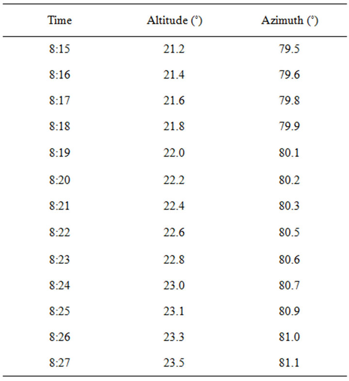
Table 1. Sun position data: Altitude and Azimuth of the Sun for Milos Island (E24˚25', N36˚40'), Zone: 2 h East of Greenwich (Milos Island, July 20, 2012).
hillshade layer is created from 08:15 am to 08:27 am and enables the selection of road segments in shadowed areas. After this process, every road segment is characterized as shadowed or not for each time minute.
The final step concerns the classification of road segments according to the exposure to direct sunlight is implemented. The classification is based on the comparison of the spatial features for each road segment with the sun position data.
Firstly, the azimuth of the road segments is checked with the azimuth of the sun for each minute. This check returns as output the selection of road segments that have identical direction (± 5˚) with the sun azimuth. It must be noticed that in this application, all rural roads are considered as two-way streets.
From this filtering, road segments that have somehow similar direction with the sun azimuth are candidates for comparison of their gradient with the sun altitude.
After this comparison, road segments that have the same gradient (± 5˚) with the sun altitude are checked if they are shadowed according to their characterization from the hillshade layers.
From this last check, roads segments that are not under shadow are considered as roads at risk as they are highly exposed to direct sunlight. It must be noted that this procedure is repeated for every minute of the time period under investigation.
At Figure 2, the methodology is presented according to all these functions.
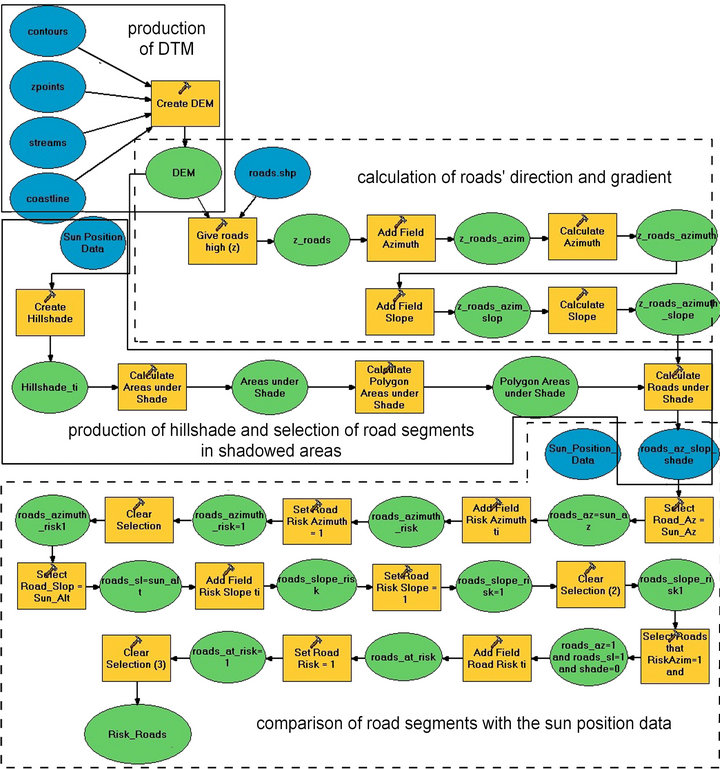
Figure 2. GIS functions for the proposed methodology.
4. Study Area
The island of Milos, Greece was selected as study area. It is located in the Cyclades with latitude 36˚40' North and longitude 24˚25' East (Figure 3). Milos is the fifth largest island in the Cyclades with an area of 151 km2 and is located in the South-West part of the Cyclades Prefecture. The width of the island from East to West is 23 km and from North to South is 13 km. The population is 4714 permanent habitants (2001 Census, Hellenic Statistical Authority). There are 26 inhabited settlements on the island.
The morphology of the island is described as low and hilly, with the eastern part being more flat compared to the western. The highest peak is Profitis Ilias (751 m). Almost all western Milos belongs to the Natura 2000 network. This is one of the reasons that this particular part of the island has not developed main road network in relation to the rest of the island.
The touristic season in the Milos Island lasts five months (May to September) and the average occupancy of existing accommodation is low except from the months of July and August, ranging from 90% to 100%.
According to Figure 4, the population of the island

Figure 3. Study area: Milos Island.
Passenger arrivals
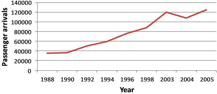
Figure 4. Passenger arrivals in Milos Isl.
during summer is increasing by 2600%. The island has not rural character as 20% of its area is covered by crop fields, 66% by pasture and only 2% of its area is urbanized. However, it has a wide developed road network (primary and secondary road network) which in total is nearby 332 km. Circulatory problems do not occur very often in Milos Island. Few problems occur during the summer season and due to the narrowness of the streets and illegal parking. Accidents are often, but noted a slight increase during summer [33].
Moreover, the statistical analysis for the road network of Milos Island (Figures 5 and 6) shows more concentration of segments at the north and northeastern part of the island, with local peaks at N-S and E-W direction.
5. Results and Discussion
The methodology described previously was applied in the study area (Milos Island) in order to analyze the exposure of the road network to direct sunlight. The results
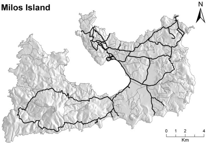
Figure 5. Road network. (Bold lines: primary network, gray lines: secondary network).
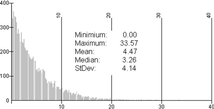
Figure 6. Distribution of road gradient values for the road network of Milos Isl.
for the route at morning of July 10, 2012 are presented at Figure 7. The route starts from point A at 08:15 am and ends at point B at 08:27 am. This time period was chosen in order to interpret the results of the proposed analysis for a season without cloud cover. Notice that one of the basic assumptions of the method is the absence of atmospheric effects (e.g. cloud cover, precipitation etc). Moreover, during the selected time period more drivers are exposed to the risk under investigation due to the significant touristic activity and increased road traffic in the study area. After the creation of the database the selected route at Milos Island was divided into straight-line road segments. This segmentation provides as output 213 straight-line road segments with 5.8 km of total length. The next step was the creation of hillshade layers for every time snapshot with the use of corresponding sun altitude and azimuth in order to exclude shadowed road segments of the route.
According to the methodology described above, the azimuth of the road network segments was calculated and compared with solar azimuth for every time snapshot in order to identify if it is affected by direct sun-light. All road segments that have the same direction (± 5˚) with the azimuth of sun were selected for the next comparison with the altitude of the sun. This threshold was added in
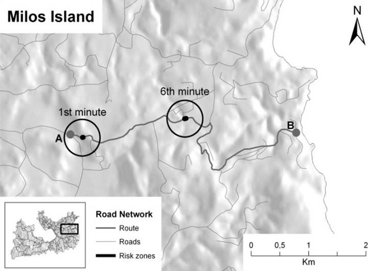
Figure 7. Road segments with high exposure to direct sunlight. Route of 12 minute duration at July 10, 2012. Circles indicate segments with high exposure.
order to overcome unclarities caused from spatial errors in road network layer as well as accuracy issues in sun position data. Similarly, the gradient for each road segment was calculated and compared with the altitude of sun. After this last check the remaining road segments that are under shadow were excluded. All the remained segments of the route are highly exposed to direct sunlight (Figure 7).
According to the results, three road segments are highly exposed to direct sunlight during the 12-minute route. The first segment is at the 230th meter from the beginning of the route, its length is 8 meters and it is exposed to direct sunlight after the 4th minute. Assuming that the vehicle is moving with a speed of 30 km per hour, it crosses the first segment at the 1st minute of the route duration. So this road segment is not a threat for the driver.
The other two segments are exposed to direct sunlight for all of the 12 minutes of the route. The first segment of them is 7 meters and follows right after the previous segment. So the vehicle will pass from this segment at the 1st minute of the route. The last segment that is at risk is at the 2.3th km from the begging of the route and its length is about 30 meters. This road segment will be crossed by the vehicle at the 6th minute. Thus, 37 meters from the total route the driver will come in direct visual contact with the sunlight.
According to this comparison, every road segment with direction towards the sun position was marked as road at risk. Figure 7 presents road segments located at regions with high exposure to direct sun-light. Notice that in this map we present only the road segments in this category with length more than 100 m. We define here as “high exposure” the exposure to direct sun-light for more than 30 hours during the summer time. As “extremely high exposure” we define the exposure to direct sun-light for more than 100 hours during the period of modeling.
6. Conclusions
In this study a GIS based spatiotemporal model for the evaluation of the exposure to direct sun radiation in rural road network is proposed. The major elements of the method are: 1) background spatial data (road network, DTM and derivables such as slope, aspect and hillshade) 2) data concerning sun position for a specific time period and 3) advanced GIS functions for spatial analysis. The integration of the above data led to the dynamic modeling and mapping of the exposure to direct sun light for the road segments in the rural network of Milos Island. By using the methodology described above all the roads segments that are in high risk, in terms of the exposure to direct sun light were specified. Mapping this risk can provide policy makers with a very useful tool for the procedure of transportation planning The identification of road segments that are at risk zones is very useful information in order to take appropriate decisions and acts to prevent road accidents. Such acts could be the creation of visual barriers in high risk areas (e.g. row of trees) or even the placement of warning signs. The implementation of the method in Milos Island showed that for the selected route of 12 minute duration at July 10, 2012 it indicated specific road segments that are in high risk.
Whether increased exposure entails increased risk of road accidents is a question related to the assumptions and limitations of the study. These assumptions are: 1) the route duration, 2) the adoption of threshold (± 5˚) for azimuth and slope filtering, 3) the absence of atmospheric effects (clouds, rainfall etc) and 4) the absence of special on site conditions affecting the direct sun-light (line of tree, buildings/constructions—use of a complete DEM etc).
The study illustrated the use of GIS technology as a spatiotemporal modeling tool, able to support decision making process. Moreover, this methodology could be a module in car navigation systems in order to provide additional information to the drivers. Future work should focus on the development of an automated real time warning system for the identification of high risk conditions in terms of extreme exposure to direct sun light. The use of GIS in co-operation with GPS seems to be the ideal technologies for the development of this system.
REFERENCES
- P. Fu and P.-M. Rich, “The Solar Analyst 1.0, User Manual,” Helios Environmental Modeling Institute (HEMI), Lawrence, 1999-2000.
- C. Chalkias, “Terms and Concepts in Geographical Information Science (GIS),” ION Editions, Athens, 2006. (in Greek)
- P. Vargues and L. Loures, “Using Geographic Information Systems in Visual and Aesthetic Analysis: The Case Study of a Golf Course in Algarve,” WSEAS Transactions on Environment and Development, Vol. 4, No. 9, 2008, pp. 774-783.
- X. Pons and M. Ninyerola, “Mapping a Topographic Global Solar Radiation Model Implemented in a GIS and Refined with Ground Data,” International Journal of Climatology, Vol. 28, No. 13, 2008, pp. 1821-1834. doi:10.1002/joc.1676
- P. Fu and P.-M. Rich, “A Geometric Solar Radiation Model with Applications in Agriculture and Forestry,” Computers and Electronics in Agriculture, Vol. 37, No. 1-3, 2002, pp. 25-35. doi:10.1016/S0168-1699(02)00115-1
- D. Rančić, B. Predić and A. Dimitrijević, “Implementation of Mobile GIS in Field Work,” WSEAS Transactions on Computers, Vol. 5, No. 11, 2006, pp. 2690-2696.
- C. Chalkias, B. Psiloglou and A. Mitrou, “A Model for Total Solar Irradiance—A GIS Approach,” WSEAS Transactions on Environment and Development, Vol. 2, No. 5, 2006, pp. 572-578.
- A. Tikniouine, A. Elfazziki and T. Agouti, “A Hybrid Model of MCDA for the GIS: Application to the Localization of a Site for the Implantation of a Dam,” WSEAS Transactions on Computers, Vol. 5, No. 3, 2006, pp. 515- 520.
- P.-A. Burrough and R. McDonnell, “Principles of Geographical Information Systems,” Oxford University Press, Oxford, 1998.
- P.-A. Longley, M. Goodchild, D.-J. Maguire and D. Rhind, “Geographic Information Systems and Science,” John Wiley & Sons, Hoboken, 2000, p. 454.
- M.-W. Lake, P.-E. Woodman and S.-J. Mithen, “Tailoring GIS Software for Archaeological Applications: An Example Concerning Viewshed Analysis,” Journal of Archaeological Science, Vol. 25, No. 1, 1998, pp. 27-38. doi:10.1006/jasc.1997.0197
- T. Bahaire and M. Elliott-White, “The Application of Geographical Information Systems (GIS) in Sustainable Tourism Planning: A Review,” Journal of Sustainable Tourism, Vol. 7, No. 2, 1999, pp. 159-174. doi:10.1080/09669589908667333
- J. Malczewski, “GIS and Multicriteria Decision Analysis,” John Wiley and Sons, New York, 1999.
- M. Dragan, E. Feoli, M. Fernetti and W. Zerihun, “Application of a Spatial Decision Support System (SDSS) to Reduce Soil Erosion in Northern Ethiopia,” Environmental Modelling & Software, Vol. 18, No. 10, 2003, pp. 861-868. doi:10.1016/S1364-8152(03)00104-X
- B. Loo, “Validating Crash Locations for Quantitative Spatial Analysis: A GIS-Based Approach,” Accident Analysis and Prevention, Vol. 38, No. 5, 2006, pp. 879-886. doi:10.1016/j.aap.2006.02.012
- S. Contini, F. Bellezza, M. D. Christou and C. Kirchsteiger, “The Use of Geographic Information Systems in Major Accident Risk Assessment and Management,” Accident Analysis and Prevention, Vol. 78, No. 1-3, 2000, pp. 223-245.
- R.-J. Schneider, R.-M. Ryznar and A.-J. Khattak, “An Accident Waiting to Happen: A Spatial Approach to Proactive Pedestrian Planning,” Accident Analysis and Prevention, Vol. 36, No. 2, 2000, pp. 193-211. doi:10.1016/S0001-4575(02)00149-5
- G. Tiwari, “Transport and Land-Use Policies in Delhi,” Bulletin of the World Health Organization, Vol. 81, No. 6, 2003, pp. 444-450.
- M. Peden, “World Report on Road Traffic Injury Prevention,” World Health Organization, Geneva, 2004.
- N. Muhlrad and S. Lassarre, “Systems Approach to Injury Control,” In: G. Tiwari, D. Mohan and N. Muhlrad, Eds., The Way Forward: Transportation Planning and Road Safety, Macmillan India Ltd., New Delhi, 2005, pp. 52- 73.
- S.-S. Pulugurtha, V.-K. Krishnakumar and S.-S. Nambisan, “New Methods to Identify and Rank High Pedestrian Crash Zones: An Illustration,” Accident Analysis and Prevention, Vol. 39, No. 4, 2007, pp. 800-811. doi:10.1016/j.aap.2006.12.001
- J.-H. Lambert, K.-D. Peterson and N.-N. Joshi, “Synthesis of Quantitative and Qualitative Evidence for Accident Analysis in Risk-Based Highway Planning,” Accident Analysis and Prevention, Vol. 38, No. 5, 2006, pp. 925- 935. doi:10.1016/j.aap.2006.03.003
- V.-B. Nakagawara, K.-J. Wood and R.-W. Montgomery, “Natural Sun-Light and Its Association to Civil Aviation Accidents,” Optometry, Vol. 75, No. 8, 2004, pp. 517-522. doi:10.1016/S1529-1839(04)70177-3
- C. Chalkias and E. Stefanakis, “Modeling Insolation in the Application Domain of a GIS,” The Proceedings of 6th Pan-Hellenic Geographical Conference, Vol. II, Thessaloniki, 2002, pp. 281-287.
- C. Chalkias and A. Faka, “A GIS-Based Spatiotemporal Analysis of the Exposure to Direct Sun Light on Rural Highways,” WSEAS Transactions on Information Science and Applications, Vol. 7, No. 1, 2010, pp. 142-151.
- V. Shankar, F. Mannering and B. Woodrow, “Effect of Roadway Geometrics and Environmental Factors on Rural Freeway Accident Frequencies,” Accident Analysis and Prevention, Vol. 27, No. 3, 1995, pp. 371-389. doi:10.1016/0001-4575(94)00078-Z
- S. Erdogan, I. Yilmaz, T. Baybura and M. Gullu, “Geographical Information Systems Aided Traffic Accident Analysis System Case Study: City of Afyonkarahisar,” Accident Analysis and Prevention, Vol. 40, No. 1, 2008, pp. 174-181. doi:10.1016/j.aap.2007.05.004
- K.-T. Anderson, “Kernel Density Estimation and K-Means Clustering to Profile road Accident Hotspots,” Accident Analysis and Prevention, Vol. 41, No. 3, 2009, pp. 359- 364. doi:10.1016/j.aap.2008.12.014
- M.-F. Hutchinson, “A New Procedure for Gridding Elevation Stream Line Data with Automatic Removal of Spurious Pits,” Journal of Hydrology, Vol. 106, No. 3-4, 1989, pp. 211-232. doi:10.1016/0022-1694(89)90073-5
- ESRI, “ARC/INFO,” Environmental Systems Research Institute, Redlands, 1995.
- United States Naval Observatory (USNO). http://aa.usno.navy.mil/data/docs/RS_OneDay.php
- L. Kumar, A. K. Skidmore and E. Knowles, “Modeling Topographic Variation in Solar Radiation in a GIS Environment,” International Journal of Geographical Information Science, Vol. 11, No. 5, 1997, pp. 475-497. doi:10.1080/136588197242266
- NTUA, “Research on Sustainable Development in Milos Island,” Technical Report in Greek, 2006. www.itia.ntua.gr/dafni