Journal of Electromagnetic Analysis and Applications
Vol.09 No.01(2017), Article ID:73771,8 pages
10.4236/jemaa.2017.91001
A Method to Calculate Inductance in Systems of Parallel Wires
Eric Deyo
Department of Physics, Fort Hays State University, Hays, KS, USA

Copyright © 2017 by author and Scientific Research Publishing Inc.
This work is licensed under the Creative Commons Attribution International License (CC BY 4.0).
http://creativecommons.org/licenses/by/4.0/


Received: December 2, 2016; Accepted: January 21, 2017; Published: January 24, 2017
ABSTRACT
This paper gives a method that maps the static magnetic field due to a system of parallel current-carrying wires to a complex function. Using this function simplifies the calculation of the magnetic field energy density and inductance per length in the wires, and we reproduce well-known results for this case.
Keywords:
Magnetostatics, Inductance, Magnetic Field

1. Introduction
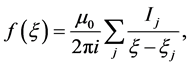
This paper points out a convenient way to calculate the magnetic field due to parallel, current-carrying wires. Defining a coordinate system such that the wires run along the z-direction, the magnetic field due to a current-carrying wire will be in the x-y-plane. We construct a complex function,  , from the com- ponents of the magnetic field:
 . The magnetic field due to a constant set of currents is determined from Ampere’s law, which we will show is equivalent to the statement that
 (1)
(1)
where ,
,  is the sum of currents enclosed by the contour c in the x-y-plane, and
  is the permeability of free space. We show that the form for the function f that reproduces the known magnetic field from a constant current i in a single wire at the position
  is
is
 (2)
(2)
where . The principle of superposition holds for Ampere’s law, so if there are many current-carrying wires, the magnetic field is the sum of magnetic fields from each wire.
These ideas are based on constant currents. In this magnetostatic case, inductance can be simply calculated. Once inductance is calculated, then it can be used to determine circuit behavior in the case when there are slowly varying currents. To be precise, in this paper, we will define inductance as relating currents to total energy stored in a magnetic field according to:
 (3)
(3)
 is the inductance matrix (including self-inductance and mutual inductance), U is the total energy stored in the magnetic field, and
  is the current carried in wire-k. We find the self-inductance per length of a wire is
 (4)
(4)
Λ and a are long and short distance cut-offs respectively. The mutual inductance per length of two wires is
 (5)
(5)
where  is the distance from wire n to wire j. These are standard results [1] [2] . Measurements and calculations of the self-inductance of actual thin wires of length
  and radius
  are consistent with (4) with
  and
and . The measured mutual inductance of two thin wires separated by a distance d is also consistent with (5) with
  [3] .
[3] .
We would like to mention that there are similar techniques using stream functions in fluids to understand vortices [4] , and also some magnetic field problems in the absence of currents [5] .
2. Relation between Ampere’s Law and a Contour Integral
Ampere’s law in SI units in integral form is
 (6)
(6)
where  is the current puncturing the area enclosed by path c, with the sign of the current given by the right hand rule.
If the path c is in the x-y plane, Ampere’s law formally looks like
 (7)
(7)
with positive currents I moving in the positive z-direction.
Consider a complex function , with
 , such that
  . Then substituting f into the contour integral
 , where the contour c in the complex plane is identical to the path of the line integral in (7) (meaning the same x- and y-values are traversed in the line integral as in the complex contour integral), yields
 (8)
(8)
Therefore,

The imaginary part of the complex integral (8) is

This can be written in terms of a parameter t that parameterizes the contour as
 (9)
(9)
The integrand is formally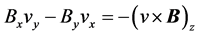 . This integrand is proportional to the z-component of the Lorentz force,
  , on a charge q. If we return to the original complex integral (8), the integral will remain the same on any change of the contour c so long as the enclosed singularities (places where f is not analytic) remain the same. In particular if the only singularities are isolated poles in f, and if we consider the contours
  as being an infinitesimal circle surrounding a pole at
  (in the same direction, clockwise or counterclockwise as the contour c), then the complex integral (8) can be written as [6]

Clearly the real and imaginary parts of contour integral can then be written in the same way, in particular
 (10)
(10)
where  is now interpreted as an infinitesimal circle around a current-carrying wire (the current being the place where the magnetic field becomes non-analytic) positioned at
 .
.
Each of the integrals in the sum in (10) can be parameterized and written in the form of (9). We can imagine each of these integrals is then proportional to the time integral of the z-component of the force on a test charge moving around an infinitesimal circle surrounding the current-carrying wire. For a single wire, the magnetic field is either parallel or antiparallel to the circle surrounding the wire, and hence the Lorentz force is zero. In the case of multiple wires, however, this is not the case. Consider two wires, which we can denote as wire-1 and wire-2. Consider a small circle around wire-1, . Let
. Let  be the magnetic field due to the current in wire-1 and
  be the magnetic field due to the current in wire-2. The magnetic field along the path
  can be written as
 . Lets consider the integral

where t parameterizes the circular path , with t2 and t1 being the value of the parameter t at the beginning and end of one circle around the wire, and
 . This integral can then be written as

The first integral on the right hand side of the above equation is zero, by the argument presented for the single wire. Let us consider the second integral on the right hand side of the above equation. If  has a radius which is very small compared to the distance from wire-1 to wire-2, then
  is approximately uniform over the circle
 . Hence the integral is approximately

since the integral of  is zero over a closed path. A similar argument can be made in the case of many wires. Therefore in the case of a magnetic field due to multiple wires
 (11)
(11)
and this means that in (10),
 (12)
(12)
This means that the imaginary part of the complex integral (8) should vanish.
We should note that there is an important condition for (12) to hold. We needed to have the radius of the circles around each of the wires be much smaller than the distance between the wires, so the magnetic field due to one wire could be considered uniform at a different wire. If a is the radius of a wire and d is the shortest distance between wires, then the condition for our theory to hold is that
 (13)
(13)
We are left with
 (14)
(14)
as our condition on f to be . This proves (1).
The residue theorem for contour integrals is [6]
 (15)
(15)
where R is the sum of the residues of f enclosed in c. The formula for the residue of a function  at a pole of order n at
  is
is
 (16)
(16)
For (14) to hold, we must have
 (17)
(17)
A simple form of f which satisfies (14) and (17) for a wire carrying current I in the z-direction at  is
is
 (18)
(18)
where . Taking the real and imaginary parts of
 , and comparing with
 , we find

 (19)
(19)
where .
.
We note that in cylindrical coordinates,  , where
  and
and . We see that (19) is precisely the field
  that one expects according to Ampere’s law.
The reader can easily see that (18) is not unique in yielding an integral whose residue obeys (17). In fact adding any analytic function to (18) will give an identical result and the condition  will hold as well. Also, there is the possibility of higher order-poles with the same residue. For the purpose of this paper, we will choose (18) because it yields the expected field for a single wire. We would also like to note that a second order pole gives a 2-dimensional dipole field for the magnetic field. Now, it is straightforward to generalize (18) to any number of wires carrying current in the z-direction, at the positions
 . We simply write
 (20)
(20)
and then take the real and imaginary parts of this to find the x and y components of the magnetic field.
3. Energy Density and Inductance
Energy density in a magnetic field is . So for the magnetic field in the x- and y-directions, we can write
 . The total energy stored in the magnetic field is then
 (21)
(21)
where the integral is over all space. The total energy stored in a magnetic field that is created by a system of currents  is related to the inductances according to
 (22)
(22)
where  is the current in wire j.
  is the mutual inductance of wires j and k and is symmetric in its indices.
  is the self inductance of wire k.
Suppose we add a current  to the system of currents in the z-direction. Let
  be the energy stored in the magnetic field in the absence of current
  and let u be the energy stored in the magnetic field in the presence of
 . We can then write
 (23)
(23)
Let  be the function
  in the absence of
  and let
  be the function
  in the presence of
 . Then
 (24)
(24)
and
 (25)
(25)
Plugging (25) into (24), then dividing by , we find that
 (26)
(26)
Plugging in the definition of f from (20), we find that
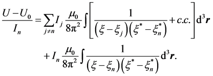 (27)
(27)
Comparing (27) with (23), we arrive at a formulae for both the self inductance and the mutual inductance. The self inductance is
 (28)
(28)
and the mutual inductance is
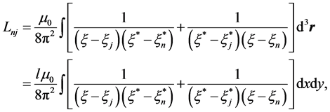 (29)
(29)
where  is the length of the wires.
The self-inductance, Equation (28), can be directly integrated. We note that . Where we set the origin of the coordinate system to the position of wire n and then convert to polar coordinates. Performing the integration in polar coordinates, we arrive at the inductance per length of the wire being
 (30)
(30)
Here we introduced long range and short range cutoffs for the integration, Λ and  respectively, and the self-inductance is only written to logarithmic accuracy, as per usual [1] .
  and
and , where
  is the radius of the wire, gives good agreement with experiment in the case of long, thin wires [3] .
The integral for the mutual inductance can also be done, but is a little more involved. Here again, we find it helpful to set the origin of the x-y coordinate system to the position of wire n, and then convert to polar coordinates. Let  and
and . Then the integral (29) becomes
 (31)
(31)
We first perform the integral over θ. We do this via residues [6] . In the first
integral on the right hand side of (31), write , and then
 , and
, and
the integral becomes a contour integral over a unit circle in the complex-u plane, traversed in the clockwise direction, call this contour-c. In the second integral on
the right hand side, we write , so
, so , and the integral becomes the
integral over a unit circle in the complex-u plane, traversed in the counterclockwise direction. We’ll call this contour c. Performing these contour integrals, we find that the integral over θ in (31) is
 (32)
(32)
In place of , for generalization purpose, we introduce the distance
  which is the distance between wires n and j. The mutual inductance per length is given by
 (33)
(33)
where we introduced a long range cutoff Λ for the integral over . Again this is written only to logarithmic accuracy. In the case of two parallel wires separated by a distance
 ,
,  gives good agreement with experiment [3] .
4. Conclusion
We note that these results for inductance are well known, but illustrate our method. In a future paper, we hope to apply this formalism to the calculation of inductance in different systems. We would also like to mention that the similarity between our formalism and the velocity stream function in fluid flow, with currents being replaced by vorticity [4] leads naturally to a nice qualitative picture of the magnetic field around arrays of wires, or around arrays of currents. In the future, we would to examine the interplay between the energy density of currents in a solid and the force between parallel current carrying wires. It is our belief that the magnetic field may break into an array of vortices similar in structure to the currents around magnetic flux lines in type II superconductors, depending on the solid [7] [8] .
Acknowledgements
The author gratefully acknowledges Luis Pauyac and Emma Diextre for helpful conversations about this subject.
Cite this paper
Deyo, E. (2017) A Method to Calculate Inductance in Systems of Parallel Wires. Journal of Electromagnetic Analysis and Applications, 9, 1-8. http://dx.doi.org/10.4236/jemaa.2017.91001
References
- 1. Landau, L.D., Lifshitz, E.M. and Pitaevskii, L.P. (1984) Electrodynamics of Continuous Media. 2nd Edition, Pergamon, Bergama.
- 2. Jackson, J.D. (1999) Classical Electrodynamics. 3rd Edition, Wiley.
- 3. Grover, F.W. (1946) Inductance Calculations: Working Formulas and Tables. Dover.
- 4. Lamb, H. (1932) Hydrodynamics. 6th Edition, Cambridge.
- 5. Stratton, J. (1941) Electromagnetic Theory. McGraw-Hill.
- 6. Whittaker, E.T. and Watson, G.N. (1950) A Course of Modern Analysis. 4th Edition, Cambridge.
- 7. Abrikosov, A.A. (1957) The Magnetic Properties of Superconducting Alloys. Journal of Physics and Chemistry of Solids, 2, 199-208.
https://doi.org/10.1016/0022-3697(57)90083-5 - 8. Feynman, R. (1955) Application of Quantum Mechanics to Liquid Helium. Progress in Low Temperature Physics, 1, 17-53.
https://doi.org/10.1016/S0079-6417(08)60077-3