Journal of Electromagnetic Analysis and Applications
Vol.06 No.06(2014), Article ID:45944,9 pages
10.4236/jemaa.2014.66011
Design and Analysis of Microstrip Antenna Arrays in Composite Laminated Substrates
S. M. Yang, C. H. Huang, C. C. Hong
Department of Aeronautics and Astronautics, National Cheng Kung University, Taiwan
Email: smyang@mail.ncku.edu.tw
Copyright © 2014 by authors and Scientific Research Publishing Inc.
This work is licensed under the Creative Commons Attribution International License (CC BY).
http://creativecommons.org/licenses/by/4.0/


Received 24 January 2014; revised 23 February 2014; accepted 21 March 2014
ABSTRACT
In high performance aerospace systems where weight and aerodynamics are of major concern, fiber reinforced composite laminates can be tailored to achieve desirable mechanical properties and accommodate low-profile microstrip antenna. This work aims at the analysis of microstrip antenna array embedded in composite laminated substrates. The size of a single antenna is first calculated by spectral domain analysis to model the effects of the substrate’s electromagnetic property and the orientation of the laminate layers. The antenna array as well as the feed network, composed of microstrip transmission lines, quarter wave-length impedance transformers, and T-junction power dividers, is then tuned to accommodate the effects of the coupling between the antenna elements and the feed network loss. The performance of the 1 × 2, 1 × 4, and 1 × 8 linear array and 2 × 2 and 2 × 4 planar array are shown to have better directivity when embedded in composite laminated substrate compared with those when attached on isotropic substrate. Both 1 × 2 and 1 × 4 arrays at 2.4 GHz are validated experimentally to achieve better coverage.
Keywords:
Microstrip Antenna, Array Antenna, Composite Laminated Substrate

1. Introduction
The concept of microstrip antennas has received attention since the development of printed circuit technology, photolithographic techniques, and low loss tangent substrates. A microstrip antenna is a thin metallic patch on dielectric substrate to radiate a relatively broad beam. In high performance aerial vehicles where size, weight, and performance are of major constraints, low-profile microstrip antennas embedded in composite laminated substrates are desirable. However, the antenna suffers from low gain, poor polarization and narrow bandwidth, and the radiation pattern is usually relatively wide with low directivity. In many applications, better antenna performance can only be accomplished by antenna array.
The radiation pattern, directivity, and gain of antenna arrays have been analyzed [1] . Shavit [2] developed a transmission line model to analyze the antenna performance. Many recent works have been proposed to increase antenna gain [3] , enlarge bandwidth [4] , and improve directivity [5] . Others also considered numerical method to analyze the performance of antenna arrays [6] . Of these works, however, the arrays were attached on isotropic substrates. Fiber reinforced composite laminates have been used in aerospace structures, where laminate layers bonded into a substrate can tailor desirable mechanical properties and facilitate embedding microstrip antenna. Smart structures with fiber optic sensor [7] , piezoelectric sensor/actuator [8] , and smart layer module [9] have been shown capable to measure and respond to operating conditions. Conformal Load-bearing Antenna Structures (CLAS) by embedding microstrip antenna have also been considered over conventional dipole or monopole antenna. Yet little is known about the effect of substrate property on antenna performance. The concept of smart skin with microstrip antenna was based on the assumption of uniform, isotropic substrate [10] -[14] . The antenna gain of a 1 × 2 array in woven composites was shown, as expected, better than the single antenna, but the conclusion was drawn by assuming the woven composites as isotropic substrate [15] . It is now known that the performance of an embedded microstrip antenna is dependent upon the substrate’s electromagnetic property [16] . This work aims at design and analysis of microstrip antenna arrays embedded in composite laminated substrates where the effects of substrate’s electromagnetic property on array performance can be understood.
2. Linear and Planar Antenna Array
An antenna array is a set of antenna elements whose signals are coordinated to achieve better antenna gain, directivity, and signal-to-noise-ratio over those of a single antenna. The total field of an array is determined by the vector addition of the antenna elements where the radiated fields interfere constructively in the desired direction(s) to achieve better directivity. In an array of identical elements, the geometrical configuration (linear or planar), the pitch (space), the excitation amplitude and phase, and the radiation pattern of each antenna element are key to array performance. Consider a 2-element linear array of infinitesimal horizontal dipoles positioned along the z-axis as shown in Figure 1(a), and the radiated field in the y-z plane is
 (1)
(1)
where  is the unit vector along
  direction,
  is the intrinsic impedance,
  is the wave number,
  is the wavelength,
  is the current of the dipole,
  is the length of the dipole,
  is the difference in phase excitation between the elements. On far-field,
  and
and , then
  and
and  for phase variations, where d is the pitch (distance) of the antenna elements, the electric field can be reduced to
 , (2)
, (2)
which is equal to the field of a single antenna element positioned at the origin multiplied by an array factor, . Thus for an N-element array, the array factor is
 , with
 , which is a function of the number of elements, the geometrical configuration, relative magnitude and phase, and pitch. For the elements with identical amplitude, phase, and pitch, the antenna gain of the array is
 (3)
(3)
In addition to linear array, planar array also provides additional variables to shape more versatile patterns with lower side lobes. Similar to the linear array in Figure 1(a), consider an array with M-element along the y-axis with pitch  and phase shift
  and with N-element in the z-axis of
  and
and . The array factor can be
written by  and in normalized form as
 ,
,
where  and
and . The antenna gain is given by
 , (4)
, (4)
 (a)
(a) (b)
(b)
Figure 1. (a) Illustration of an N-element linear array and (b) a rectangular microstrip antenna with microstrip feed line.
where  and
and  are the directivities of y- and z-direction. The above analyses facilitate synthesizing versatile pattern such as multi-beam or shaped-beam in microstrip antenna array that cannot be achieved by a single antenna element.
3. Spectral Domain Analysis
It is believed that a load-bearing structural component integrating microstrip antenna shall improve aerodynamic and communication performance. A composite laminated substrate is characterized by the diagonal permittivity matrix of each of the anisotropic layers , with permittivity
  along the fiber direction and
  along the other two normal axes,

 the relative permittivity,
  in the orthogonal direction, and
  in the free-space. In practice, the antenna’s axes (x-y-z) may not necessarily be co-linear with any of the substrate’s principal (1-2-3) axes, and that leads to a non-diagonal permittivity matrix. For the antenna attached on an anisotropic layer, the permittivity matrix becomes non-diagonal and the 5 distinctive non-zero elements (dielectric constants) are functions of the antenna orientation relative to the substrate’s fiber direction.
In spectral domain, the electromagnetic wave propagation can be solved by the electric and magnetic Hertzian potentials with the coordinate transformation between the antenna’s axes and the substrate’s axes
 (5a)
(5a)
 (5b)
(5b)
where  and
and  are the magnetic and electric Hertz potential, respectively, and
  is the unit vector. The wave equation in terms of the Fourier transform of the Hertz potential pair can be written as
 (6a)
(6a)
 (6b)
(6b)
where  and
and  is the operating frequency,

 and
and  are the Fourier variables of the wave numbers with respect to y- and z-axis, respectively, and the solutions are
 (7a)
(7a)
 (7b)
(7b)
Similarly for the air medium, the wave equations can be written by
 (8a)
(8a)
 (8b)
(8b)
and the solutions are
 (9a)
(9a)
 (9b)
(9b)
where  is the substrate thickness,
  and
and . The coefficients A,
  , B,
, B,  ,
,  and
and  in Equations (7) and (9) are determined by the boundary conditions at the interface of ground plane, the adjacent layers, and the antenna layer.
The electric field components on the top layer can then be represented by  and
and  in matrix form in spectral domain
 (10)
(10)
where  and
and  are the Fourier transforms of the current densities on the antenna. The immittance matrix is function of fiber direction and layer thickness, dielectric constants
  along the fiber direction and
  along the other two principal axes. The antenna’s spectral current components can therefore be solved by modal analysis in terms of the base functions
  and
and . For a rectangular microstrip antenna of dimension L × W, the base functions can be selected similar to [16] as
 (11a)
(11a)
 (11b)
(11b)
In spectral domain, they are
 (12a)
(12a)
 (12b)
(12b)
where  is the Dirac delta function. The coefficients of the base functions can be determined by the eigensolution associated with Equation (10). The dimension, resonant frequency, and the radiation pattern of an embedded microstrip antenna can then be calculated by the surface currents.
4. Antenna Array Design
In Conformal Load-bearing Antenna Structures (CLAS), the embedded microstrip antenna is preferable to be on the same laminate layer with the feed network because of the compatibility in fabrication process. The smart layer module utilizing the flexible printed circuit process to encapsulate sensor/actuator has been recently developed [9] . By the same concept, the antenna array and feed network are patterned by a copper film of 17.5 mm thickness on polyimide layer of 12.5 mm thickness (CRI-0512S, DuPont). It is then embedded inside a 20 mm thickness composite laminated substrate composed of 6 anisotropic layers (Wah Lee) in [45/-45/45/45/-45/45] symmetric configuration. The dielectric constant test is conducted by measuring the capacitance of a sample layer between two electrodes at the desired operation frequency and the second run is measured without the sample. The ratio of these two values is the dielectric constant ( along the fiber direction and
  4.7 across the fiber direction).
A rectangular microstrip antenna on isotropic substrate is commonly analyzed by the transmission line and cavity model. For the coordinate system as shown in Figure 1(b), the resonant frequency of the dominant TM010
mode is given by  where
where  is the effective length,
 is the length,
and  is the extended incremental length due to fringing effects,

 for
for , W is the width of the antenna element,
 , h is the substrate thickness, c is the speed of light in free space, and
  and
and  are the effective relative and dielectric constants, respectively. The transmission line theory is employed to model the antenna as two parallel radiating slots labeled as #1 and #2 as shown in Figure 1(b). The antenna pattern is calculated by the cavity model of two parallel uniform magnetic line sources of length W separated by a distance
  along the y-direction. The electric field in the x-y plane (θ = 90˚, 0˚ ≤ f ≤ 90˚ and 270˚ ≤ f ≤ 360˚) is
 (13)
(13)
with  where
where  is the slot voltage across the radiating edges. For a rectangular microstrip antenna operating at 2.4 GHz, its size from the empirical formula is L = 29.81 mm and W = 38.24 mm on isotropic substrate
 .
.
The above design does not take into account the substrate’s electromagnetic property, the coupling between the antenna elements or the feed network loss to the elements. For a single antenna element embedded in the [45/-45/45/45/-45/45] composite laminated substrate, spectral domain analysis by Equation (10) shows that antenna is L = 36.34 mm and W = 46.61 mm. It is scaled proportionally, about 22% increase in both length and width, from the empirical transmission line and cavity model. The antenna size and the performance are strongly influenced by the substrate’s electromagnetic property and the orientation between the antenna’s optical axis and the laminate layer’s fiber direction. Consider a 1×2 antenna array. All elements in the array shall have the same phase excitation  for maximum radiation (broadside, θ = 90˚).
The pitch between the elements can be any but preferably less than one wavelength  The feed network is composed of transmission lines, quarter-wavelength impedance transformers and T-junction power divider. The antenna frequency will be deviated by the coupling between the two elements and the feed network. Simulation results show that the pitch between the antenna elements is 77.5 mm
 . The return loss
  is shown in Figure 2(a) with 5.2 dB antenna gain, about 2.2 dB higher than the single element, and the far field pattern (E-plane) in Figure 2(b). The antenna gain of the 1 × 2 array should have been 6.9 dB from Equation (3) if neglecting the effects of the coupling between the two antenna elements and the feed network loss. Figure 3 is the comparison of the far field patterns of the 1 × 2 linear array on isotropic substrate
  and on the composite laminated substrate (
 and
and ), where both are scaled by the gain at
 . The radiation pattern of the latter has better directivity, thus better efficiency.
For the 1 × 4 antenna array on the composite laminated substrate operating at 2.4 GHz, the feed network is composed of three T-junction power dividers and four transmission lines. Simulations by the spectral domain

 (a) (b)
Figure 2. The 1 × 2 rectangular microstrip antenna array on the composite laminated substrate operating at 2.4 GHz, (a) simulation (fine line) and experimental verification (solid line) of the return loss, and (b) the far field pattern of E-plane.

Figure 3. The far field of the 1 × 2 antenna array operating at 2.4 GHz on isotropic substrate (pattern with diamond) and on composite laminated substrate.
analysis show that the pitch is 79.4 mm . Figure 4(a) shows the return loss of the array, where the antenna gain is 7.0 dB, about 4.0 dB higher than the single antenna element. The array factor in Equation (3) predicts the gain should have been 10.1 dB; however, the antenna coupling effect and the feed network loss reduce the gain to 7.0 dB. The far field pattern of electric field with better directivity is shown in Figure 4(b).
The 1 × 8 antenna array with the pitch at 77.5 mm  on the composite laminated substrate operating at 2.4 GHz has the antenna gain 8.7 dB in Figure 5(a). The far field pattern (E-plane) in Figure 5(b). The gain should have been higher from Equation (3) when neglecting the antenna coupling effect and the feed network. Table 1 summarizes comparison of the antenna gain of the linear arrays. The bandwidth maintains at about 2% ~ 5%. The effects of the substrate’s electromagnetic property on antenna gain become more significant as the array size increases.

 (a) (b)
Figure 4. The 1 × 4 rectangular microstrip antenna array operating at 2.4 GHz, (a) simulation (fine line) and experimental (solid line) verification of the return loss, and (b) the far field pattern of E-plane.

 (a) (b)
Figure 5. A 1 × 8 rectangular microstrip antenna array operating at 2.4 GHz, (a) the return loss and (b) the far field pattern.

Table 1. Comparison of the antenna gain with the effects of substrate’s electromagnetic property, the coupling between the antenna elements, and the feed network loss.
In addition to linear array, a planar array has the maximal gain when
 (14)
(14)
Since it is desirable to have the maximum directed toward  (z-axis), then
  and
and . Thus all antenna elements shall have the same phase excitation with the pitch less than one wavelength
 . A 2 × 2 array with the feed network is shown in Figure 6(a), where the pitch in y- and z-axis are 62.8 mm
  . The antenna gain is 7.6 dB, which is less than the prediction of 14.0 dB by Equation (4) because of the effects of the coupling between the antenna elements and the feed network. The antenna gain is still superior to the 1 × 4 linear array of 7.0 dB. With the same number of antenna elements, the performance of planar array is better than that of the linear array. The 2 × 4 antenna array operating at 2.4 GHz on composite laminated substrate is shown as Figure 6(b) with the y- and z-axis pitch of 62.8 mm. The feed network is composed of seven T-junction power dividers and eight transmission lines, and the antenna gain is 9.7 dB. Table 1 also shows the comparison of antenna gain, where the gain increases about 2 dB when the number of the antenna element doubles.
The microstrip antenna arrays of 1 × 2 and 1 × 4 are measured to verify the above simulation results. Figure 2(a) shows the return loss measurement by network analyzer (Agilent Technologies E5071B) is in good agreement with the simulation. Similar return loss measurement of the 1 × 4 antenna array is also shown in Figure 4(a). Previous work of a single antenna element on composite laminated substrates shows that the resonant frequency is a function of the substrate’s property. In this work, the resonant frequency of an antenna array is shown influenced not only by the substrate’s electromagnetic property, but also by the coupling between the antenna elements and the feed network loss. The performance of the antenna arrays are validated by connecting to a wireless access router to show that the coverage of the 1 × 2 and 1 × 4 antenna arrays has improved 40% and 80%, respectively.
 (a)
(a)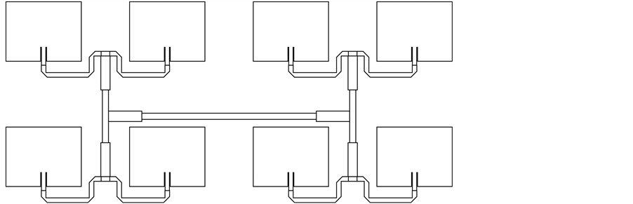 (b)
(b)
Figure 6. (a) 2 × 2 and (b) 2 × 4 rectangular microstrip antennas in planar array operating at 2.4 GHz (not to scale).
5. Summary and Conclusions
1) Recent development of Conformal Load-bearing Antenna Structure (CLAS) by embedding microstrip antenna inside composite laminated substrates is desirable to have sufficient structural and antenna performance. Microstrip antenna has the advantage of low profile, low weight and conformability for minimizing disturbances to aerodynamic field. The design of rectangular microstrip antenna arrays operating at 2.4 GHz is presented in this work. The single antenna element is first calculated by spectral domain analysis to model the composite substrate’s electromagnetic property, and the performance of antenna array is then determined by considering the coupling between the antenna elements and the feed network loss.
2) The antenna array and microstrip feed lines are deposited on polyimide layer which is then embedded inside [45/-45/45/45/-45/45] substrates. Analysis shows that the size of antenna element in composite laminated substrate is 22% higher both in length and width over that in isotropic substrate. Both the 1 × 2 and 1 × 4 linear arrays are validated experimentally by connecting to a wireless access router to show improvement of the coverage distance. About 40% improvement by rectangular microstrip antenna array is increased by the 1 × 2 array and 80% by the 1 × 4 array.
3) The feed network of microstrip transmission lines is shown to influence significantly the frequency of an antenna array. The pitch distance of 1 × 2, 1 × 4, 1 × 8, 2 × 2 and 2 × 4 arrays are determined by tuning the length of the transmission lines. The antenna gain predictions in Equations (3) and (4) are strongly influenced by the substrate’s electromagnetic properties and the coupling effect of the antenna elements in the array. The antenna gain increase in the planar array is higher than that in the linear array, but the feed network design is more complicated.
Acknowledgements
This work was supported in part by the National Science Council, Taiwan, under NSC100-2221-E006-098-MY3.
References
- Pozar, D.M. and Kaufman, B. (1990) Design Considerations for Low Sidelobe Microstrip Arrays. IEEE Transactions on Antennas and Propagation, 38, 1176-1185. http://dx.doi.org/10.1109/8.56953
- Shavit, R. (1994) Dielectric Cover Effect on Rectangular Microstrip Antenna Array. IEEE Transactions on Antennas and Propagation, 42, 1180-1184. http://dx.doi.org/10.1109/8.310012
- Ma, Z. and Vandenbosch, G.A.E. (2012) Low-Cost Wideband Microstrip Arrays with High Aperture Efficiency. IEEE Transactions on Antennas and Propagation, 60, 3028-3034. http://dx.doi.org/10.1109/TAP.2012.2194685
- Han, L. and Wu, K. (2012) 24-GHz Bandwidth-Enhanced Microstrip Array Printed on a Single-Layer Electrically-Thin Substrate for Automotive Applications. IEEE Transactions on Antennas and Propagation, 60, 2555-2558.
- Karabey, O.H., Gaebler, A., Strunck, S. and Jakoby, R. (2012) A 2-D Electronically Steered Phased-Array Antenna with 2 × 2 Elements in LC Display Technology. IEEE Microwave Theory and Techniques, 60, 1297-1306. http://dx.doi.org/10.1109/TMTT.2012.2187919
- Zhao, X.L., Qian, T., Mei, G., Kwan, C., Zane, R., Walsh, C., Paing, T. and Popovic, Z. (2007) Active Health Monitoring of an Aircraft Wing with an Embedded Piezoelectric Sensor/Actuator Network: II. Wireless Approaches. Smart Materials and Structures, 16, 1218-1225. http://dx.doi.org/10.1088/0964-1726/16/4/033
- Yang, S.M. and Bian, J.J. (1996) Vibration Suppression Experiment of Composite Laminated Plates by Embedded Piezoelectric Sensor and Actuator. Smart Materials and Structures, 5, 501-507. http://dx.doi.org/10.1088/0964-1726/5/4/014
- Yang, S.M. and Jeng, C.A. (1996) Structural Vibration Suppression by Concurrent Piezoelectric Sensor and Actuator. Smart Materials and Structures, 5, 806-813. http://dx.doi.org/10.1088/0964-1726/5/6/011
- Yang, S.M., Hung, C.C. and Chen, K.H. (2005) Design and Fabrication of a Smart Layer Module in Composite Laminated Structures. Smart Materials and Structures, 14, 315-320. http://dx.doi.org/10.1088/0964-1726/14/2/003
- You, C.S., Hwang, W. and Eom, S.Y. (2005) Design and Fabrication of Composite Smart Structures for Communication using Structural Resonance of Radiated Field. Smart Materials and Structures, 14, 441-448. http://dx.doi.org/10.1088/0964-1726/14/2/019
- Zhao, W.J., Li, L.W., Li, E.P. and Xiao, K. (2012) Analysis of Radiation Characteristics of Conformal Microstrip Arrays Using Adaptive Integral Method. IEEE Transactions on Antennas and Propagation, 60, 1176-1181. http://dx.doi.org/10.1109/TAP.2011.2173135
- Ramesh, P. and Washington, G. (2009) Analysis and Design of Smart Electromagnetic Structures. Smart Materials and Structures, 18.
- Son, S.H., Eom, S.Y. and Hwang, W. (2008) Development of a Smart-Skin Phased Array System with a Honeycomb Sandwich Microstrip Antenna. Smart Materials and Structures, 17, 1-9. http://dx.doi.org/10.1088/0964-1726/17/3/035012
- Jang, H.K., Lee, W.J. and Kim, C.G. (2011) Design and Fabrication of a Microstrip Patch Antenna with a Low Radar Cross Section in the X-Band. Smart Materials and Structures, 20.
- Yao, K., Jiang, M., Zhou, D., Xu, F., Zhao, D., Zhang, W., Zhou, N., Jiang, Q. and Qiu, Y. (2011) Fabrication and Characterization of Microstrip Array Antennas Integrated in the Three Dimensional Orthogonal Woven Composite. Composites Part B: Engineering, 42, 885-890. http://dx.doi.org/10.1016/j.compositesb.2011.01.006
- Yang, S.M. and Hung, C.C. (2009) Modal Analysis of Microstrip Antenna on Fiber Reinforced Anisotropic Substrates. IEEE Transactions on Antennas and Propagation, 57, 792-796. http://dx.doi.org/10.1109/TAP.2009.2013443