Journal of Electromagnetic Analysis and Applications
Vol.5 No.1(2013), Article ID:27029,4 pages DOI:10.4236/jemaa.2013.51001
Calculation of Start-Oscillation-Current for Lossy Gyrotron Traveling-Wave Tube (Gyro-TWT) Using Linear Traveling-Wave Tube (TWT) Parameter Conversions
![]()
Department of Electrical and Computer Engineering, University of Colorado, Colorado Springs, USA.
Email: hsong@uccs.edu
Received November 13th, 2012; revised December 13th, 2012; accepted December 25th, 2012
Keywords: Start-Oscillation-Current; Gyro-TWT; TWT; Lossy; Stable; Competing Mode
ABSTRACT
The start-oscillation-current of a gyro-TWT (gyrotron traveling-wave tube) determines the stable operating current level of the device. The amplifier is susceptible to oscillations when the operating current level is higher than the start-oscillation current. There are several ways of calculating the start-oscillation current, including using the linear and nonlinear theory of a gyro-TWT. In this paper, a simple way of determining the start-oscillation current of lossy gyro-TWT is introduced. The linear TWT parameters that include the effects of synchronism, loss, and gain, were converted to gyro-TWT parameters to calculate the start-oscillation-current. The dependence on magnetic field, loss, and beam alpha was investigated. Calculations were carried out for a V-band gyro-TWT for both operating and competing modes. The proposed method of calculating the start-oscillation current provides a simple and fast way to estimate the oscillation conditions and can be used for the design process of a gyro-TWT.
1. Introduction
The gyro-TWT (gyrotron traveling-wave tube) has long been viewed as an extremely promising device due to its high-power and broadband capabilities. Potential applications include radar, communication, surveillance, and scientific research [1]. However, in order for gyro-TWT to work properly, the interaction with competing mode must be suppressed. The beam current level where the unwanted oscillation takes place is called the “start-oscillation-current”  for gyro-TWT. Therefore in gyroTWT, it is critical to operate the amplifier below Is to ensure stability of the device. One way to increase Is is to apply loss to the gyro-TWT circuit. Calculation results of Is employing linear theory [2-4] and nonlinear theory [5] were reported for lossy gyro-TWT. However, using these methods require in-depth analysis on linear and nonlinear theories of gyro-TWT. In this paper, a simple method of obtaining Is for lossy gyro-TWT by using the linear-TWT parameters is introduced. By using the linear TWT parameter conversions, the expression for Is for the gyroTWT was obtained. The parameter conversion process and the calculation results for Is for gyro-TWT are presented.
2. Conversion of Linear TWT Parameters to Gyro-TWT
The gain parameter of a linear lossy TWT that corresponds to the start-oscillation condition can be expressed by Equation (1) [6]. For gyro-TWT, the gain parameter is described as Equation (2) [7]. By combining Equation (1) used in a linear TWT and Equation (2) used in a gyro-TWT (by setting Cst = Cg), the start oscillation current for lossy gyro-TWT can be expressed by Equation (3).
 (1)
(1)
 (2)
(2)
 (3)
(3)
Here LdB is the total loss of the circuit in dB, N is the circuit length in wavelength, kc is the cutoff wavenumber , kb is the beam wavenumber
 , Ib is the beam current, Fmn is defined in Equation (4), and εv is defined in Equation (5).
 (4)
(4)
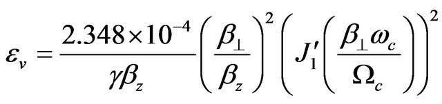 (5)
(5)
Here Jm is the Bessel function of order m, kmn is the mth Bessel root defined by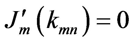 , n is the radial mode number, m is the azimuthal mode number, Ra is the guiding center radius, a is the waveguide radius, βz is the axial velocity normalized by the speed of light, β^ is the transverse velocity normalized by the speed of light, ωc is the cutoff frequency of the waveguide, and Ωc is the relativistic cyclotron frequency. The comparison between critical parameters of linear and gyro-TWT is shown in Table 1.
3. Calculated Results and Discussion
In order to validate the Is calculation method proposed above, a V-band (60 GHz) TE11 gyro-TWT was chosen to evaluate the Is values. Figure 1 shows the dispersion diagram of the V-band TE11 gyro-TWT for α = 0.85, Vb = 100 kV, and . The waveguide mode expressed as
 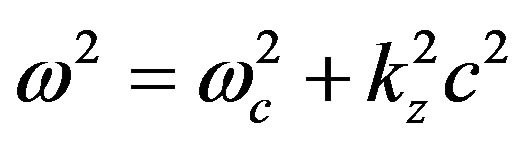 is shown in parabolas and the beam mode which can be described as ω = sΩc + kzvz is shown in straight lines up to fourth harmonic. Here, ω is the frequency, kz is the axial wavenumber, c is the speed of light, s is the harmonic number, and vz is the axial velocity of the beam. The operating point is where the TE11 waveguide mode grazes with the s = 1 beam mode. The possible competing mode interactions occur when the waveguide mode intersects with the beam mode. These include TE11 and TE21 with s = 2, TE01 with s = 3, and TE02 with s = 4 beam modes. The specification
Table 1. Conversion of linear TWT parameters to gyroTWT [7-8].
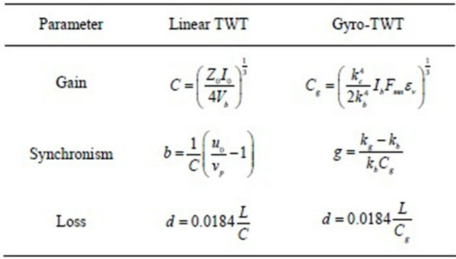 Z0: Circuit impedance; vp: Phase velocity; Vb: Beam voltage; L: Loss per wavelength; u0: Beam velocity; ka: Waveguide wavenumber.
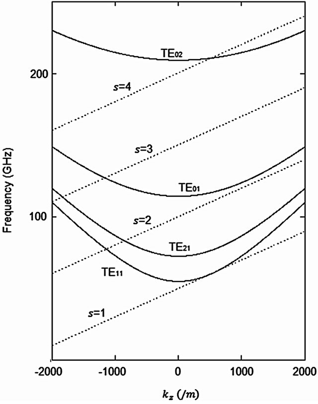
Figure 1. Dispersion diagram of a TE11 60 GHz gyro-TWT for α = 0.85, Vb = 100 kV, and . Waveguide modes (TE11, TE21, TE01, TE02) and beam modes (s = 1, 2, 3, 4) are shown.
of the V-band TE11 gyro-TWT is described in Table 2. The calculated Is using Equation (3) is shown in Figures 2-5 under various conditions. Figure 2 shows dependence of Is on circuit loss, LdB, for several values of beam velocity ratio, α, for the operating TE11 mode with  and Vb = 100 kV. The
  indicates operating magnetic field, Bo, normalized by the grazing magnetic field, Bg. As LdB increases, Is increases which indicates that with higher value of LdB, the device becomes more stable. For fixed value of LdB, Is increases as α decreases. This indicates that the loss stabilizes the device and the gyro-TWT becomes unstable for higher values of α. Figure 3 describes Is change with
  of the operating TE11 mode for several values of beam voltage, Vb, for fixed values of α = 0.85 and LdB = 100 dB. For
 , Is decreases as
  increases. For fixed value of
 , Is is higher for higher Vb when
 . For
. For , higher beam voltage makes the device unstable and as the operating magnetic field increases the device becomes more stable due to increasing |kz|. Figure 4 shows Is as a function
  for several values of α and fixed values of Vb = 100 kV and LdB = 100 dB. For
 , Is decreases as
 increases. For fixed value of
 , Is in
Table 2. Specifications of the V-band TE11 gyro-TWT.
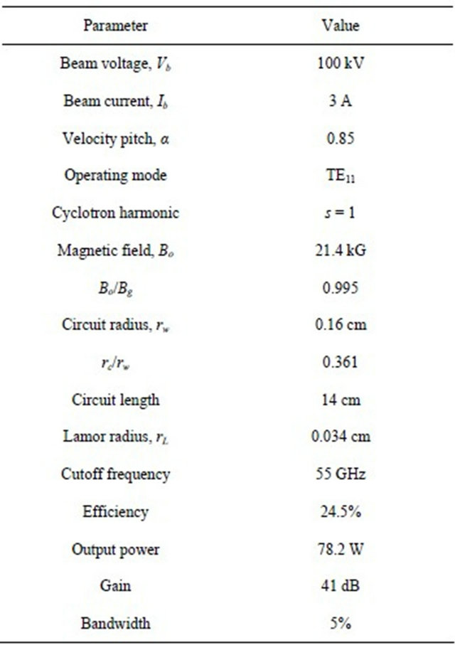
rc: Guiding center radius.
Figure 2. Start-oscillation-current, Is, for the operating TE11 mode as a function of loss, LdB, for different values of beam velocity ratio, α, and the fixed value of the operating magnetic field normalized by the grazing magnetic field, Bo/Bg = 1.5, and beam voltage, Vb = 100 kV.

Figure 3. Start-oscillation-current, Is, for the operating TE11 mode as a function of Bo/Bg for different values of beam voltage, Vb, and fixed values of α = 0.85 and LdB = 100 dB.
Figure 4. Start-oscillation-current, Is, for the operating TE11 mode as a function of Bo/Bg for different values of α and fixed values of Vb = 100 kV and LdB = 100 dB.
creases as α increases for . For
. For
 , device is more stable for lower alpha because when the perpendicular component of the velocity decreases, the gyro-TWT beam-wave interaction becomes
Figure 5. Dispersion diagram of a TE11 60 GHz gyro-TWT for α = 0.85, Vb = 100 kV, and Bo/Bg = 1.5. Waveguide modes (TE11, TE21, TE01, TE02) and beam modes (s = 1, 2, 3) are shown.
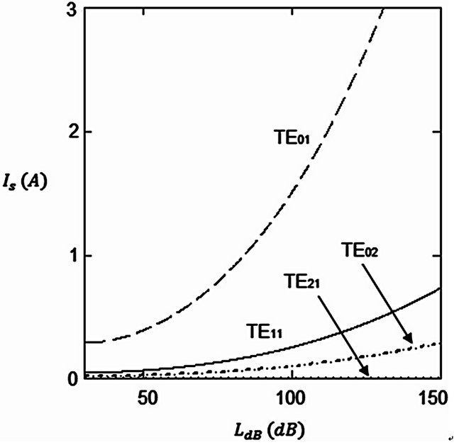
Figure 6. Start-oscillation-current, Is, as a function of loss, LdB, for different modes. Fixed values of α = 0.85, Vb = 100 kV, and Bo/Bg = 1.5 were assumed.
weaker. Figure 5 shows the dispersion diagram of the device for α = 0.85, Vb = 100 kV, and . Figure 6 describes Is as a function of LdB for four different modes: TE11, TE21, TE01, and TE02. Fixed values of α
= 0.85, Vb = 100 kV, and  were assumed. The lowest Is occurs for the TE21 and the TE01 mode exhibits the highest Is value. As can be seen in Figure 5, this is due to TE21 mode having the lowest |kz| value and the TE01 mode having the highest |kz| value at the intersection of the beam-wave dispersion diagram. The Is of the TE01 mode is the most sensitive to LdB variation.
4. Summary and Conclusion
In this paper, an expression for Is for lossy gyro-TWT was derived using linear TWT parameter conversions. For V-band TE11 gyro-TWT, Is was calculated for various parameters including loss, beam voltage, magnetic field, and beam velocity ratio. The method introduced in this paper can be used to quickly estimate the Is values of a lossy gyro-TWT.
REFERENCES
- H. H. Song, D. B. McDermott, Y. Hirata, L. R. Barnett, C. W. Domier, H. L. Hsu, T. H. Chang, W. C. Tsai, K. R. Chu and N. C. Luhmann Jr., “Theory and Experiment of a 94 GHz Gyrotron Traveling-Wave Amplifier,” Physics of Plasmas, Vol. 11, No. 5, 2004, pp. 2935-2941. doi:10.1063/1.1690764
- Q. S. Wang, D. B. McDermott and N. C. Luhmann Jr., “Demonstration of Marginal Stability Theory by a 200- kW Second-Harmonic Gyro-TWT Amplifier,” Physical Review Letters, Vol. 75, No. 23, 1995, pp. 4322-4355. doi:10.1103/PhysRevLett.75.4322
- C. S. Kou, Q. S. Wang, D. B. McDermott, A. T. Lin, K. R. Chu and N. C. Luhmann Jr., “High-Power Harmonic GyroTWT’s—Part I: Linear Theory and Oscillation Study,” IEEE Transactions on Plasma Science, Vol. 20, No. 3, 1992, pp. 155-162. doi:10.1109/27.142815
- Y. Y. Lau, K. R. Chu, L. R. Barnett and V. L. Granatstein, “Gyrotron Traveling Wave Amplifier: I. Analysis of Oscillations,” International Journal of Infrared and Millimeter Waves, Vol. 2, No. 3, 1981, pp. 373-393. doi:10.1007/BF01007408
- W. C. Tsai, T. H. Chang, N. C. Chen, K. R. Chu, H. H. Song and N. C. Luhmann Jr., “Absolute Instabilities in a High-Order-Mode Gyrotron Traveling-Wave-Amplifier,” Physical Review E, Vol. 70, No. 5, 2004, Article ID: 056402. doi:10.1103/PhysRevE.70.056402
- R. W. Grow and D. R. Gunderson, “Starting Conditions for Backward-Wave Oscillators with Large Loss and Large Space Charge,” IEEE Transactions on Electron Devices, Vol. 17, No. 12, 1970, pp. 1032-1039. doi:10.1109/T-ED.1970.17123
- M. Caplan, “The Gyrotron: An Application of the Relativistic Bunching of Electrons to the Generation of Intense Millimeter Microwave Radiation,” Ph.D. Thesis, University of California, Los Angeles, 1986.
- A. S. Gilmour, “Principles of Traveling Wave Tubes,” Artech House Inc., Norwood, 1994, pp. 273-305.