Journal of Electromagnetic Analysis and Applications
Vol.4 No.4(2012), Article ID:18613,9 pages DOI:10.4236/jemaa.2012.44019
Spherical Near-Field - Far-Field Transformation for Quasi-Planar Antennas from Irregularly Spaced Data
![]()
Department of Electronic and Computer Engineering, University of Salerno, Fisciano, Italy.
Email: fdagostino@unisa.it
Received February 12th, 2012; revised March 15th, 2012; accepted March 25th, 2012
Keywords: Antenna Measurements; Near-Field - Far-Field Transformations; Spherical Scanning; Nonredundant Sampling Representations of Electromagnetic Fields; Probe Positioning Errors Compensation
ABSTRACT
An effective near-field - far-field (NF - FF) transformation with spherical scanning for quasi-planar antennas from irregularly spaced data is developed in this paper. Two efficient approaches for evaluating the regularly spaced spherical samples from the nonuniformly distributed ones are proposed and numerically compared. Both the approaches rely on a nonredundant sampling representation of the voltage measured by the probe, based on an oblate ellipsoidal modelling of the antenna under test. The former employs the singular value decomposition method to reconstruct the NF data at the points fixed by the nonredundant sampling representation and can be applied when the irregularly acquired samples lie on nonuniform parallels. The latter is based on an iterative technique and can be used also when such a hypothesis does not hold, but requires the existence of a biunique correspondence between the uniform and nonuniform samples, associating at each uniform sampling point the nearest irregular one. Once the regularly spaced spherical samples have been recovered, the NF data needed by a probe compensated NF - FF transformation with spherical scanning are efficiently evaluated by using an optimal sampling interpolation algorithm. It is so possible to accurately compensate known positioning errors in the NF - FF transformation with spherical scanning for quasi-planar antennas. Some numerical tests assessing the accuracy and the robustness of the proposed approaches are reported.
1. Introduction
Near-field - far-field (NF - FF) transformation techniques [1-5] have been widely investigated in the last four decades and used for applications ranging from cellular phone antennas to large phased arrays and complex multi-beam communication satellite antennas. They allow one to overcome the drawbacks which, for electrically large radiating systems, make unpractical the measurement of the antenna pattern in a conventional FF range and represent the better choice when complete pattern and polarization measurements are required. Moreover, they provide the necessary information to determine the radiating field on the surface of the antenna. Such an information can be properly used for the diagnostics of surface errors in a reflector antenna or of faulty elements in an array (microwave holographic diagnostics [6]). Commonly, the measured NF data are transformed into FF patterns by using an expansion of the field of the antenna under test (AUT) in terms of modes, namely, a complete set of solutions of the vector wave equation in the region outside the antenna. Plane, cylindrical, or spherical waves are generally used. The type of employed modal expansion determines the kind of the NF scanning surface, which accordingly will be a plane, a cylinder, or a sphere. The orthogonality properties of the modes on such surfaces are then exploited to obtain the modal expansion coefficients, which allow the reconstruction of the AUT far field. Among the NF - FF transformation techniques, the one employing the spherical scanning has attracted remarkable attention since it allows the reconstruction of the complete radiation pattern of the AUT from a single set of NF measurements [7-16]. However, the computational effort is much greater than that required by planar and cylindrical NF facilities. The standard NF - FF transformation with spherical scanning [12] has been properly modified in [13] by taking into account the properties of spatial bandlimitation of electromagnetic (EM) fields [17]. Accordingly, the highest spherical wave to be considered has been rigorously fixed by the bandlimitation properties and the number of data on the parallels has resulted to be decreasing towards the poles. Moreover, the application of the nonredundant sampling representations of the EM field [18] has allowed a significant reduction of the number of needed NF data when considering antennas having one or two predominant dimensions [13]. These results have been achieved by assuming the AUT as enclosed in a prolate or oblate ellipsoid and by developing an optimal sampling interpolation (OSI) formula, which allows the reconstruction of the data required by the abovementioned NF - FF transformation. The ideal probe assumption, originally made in [13], has been removed in [14] so developing an effective probe compensated spherical NF - FF transformation technique for elongated or quasiplanar antennas. Finally, an efficient NF - FF transformation with spherical scanning, tailored to these kinds of antennas and based on different but very flexible AUT modellings, has been proposed in [15].
It must be stressed that the inaccurate control of the positioning systems and their finite resolution do not allow one to acquire the NF data at the points fixed by the sampling representation. On the other hand, their position can be accurately determined by using optical devices. Accordingly, the development of an accurate and stable reconstruction process from irregularly spaced data appears indispensable. In this framework, a procedure based on the conjugate gradient iteration method and using the unequally spaced fast Fourier transform (FFT) [19] has been proposed to compensate the positioning errors in the plane-rectangular [20] and spherical [21] scannings. Unfortunately, such a procedure cannot be applied to the scanning techniques exploiting the nonredundant sampling representations of EM field, wherein the NF data needed by the corresponding classical NF - FF transformations are recovered from the acquired nonredundant ones by means of proper OSI formulas. Since the formulas for the direct reconstruction from nonuniform samples are not user friendly, unstable, and valid only for particular sampling points arrangements, it is more convenient [22] to recover the uniform samples from the nonuniform ones and then determine the value at any point of the scanning surface via an accurate and stable OSI formula. In this context, an approach based on an iterative technique has been proposed to recover the uniformly distributed samples from the irregularly spaced ones on planar [22], cylindrical, and FF spherical surfaces [23]. However, such an iterative technique results to be convergent only if it is possible to build a biunique correspondence associating at each uniform sampling point the nearest nonuniform one. With reference to a plane-polar and cylindrical geometry, this limitation has been overcome in [24] and [25], respecttively, by developing an approach based on the use of the singular value decomposition (SVD) method [26]. This latter approach allows one to take advantage of data redundancy for increasing the algorithm stability, but can be conveniently applied when the two-dimensional problem of the uniform samples recovery can be tackled as two independent one-dimensional ones, otherwise the dimension of the involved matrix would become very large, thus requiring a huge computational effort. Both the approaches have been compared and experimentally validated in the cylindrical scanning case [27]. At last, these approaches have been applied to the positioning errors compensation in the spherical NF - FF transformation for elongated antennas [28].
The aim of this paper is to develop and compare numerically analogous algorithms to compensate the probe positioning errors in the NF - FF transformation with spherical scanning for quasi-planar antennas, which will be now assumed as enclosed in an oblate ellipsoid (see Figure 1) instead of a prolate one. Effective techniques, applicable to all kind of antennas, will be so available for compensating the positioning errors in such a widely employed NF - FF transformation.
The paper is organized in six sections. Section 2 briefly describes the classical probe compensated NF - FF transformation with spherical scanning as modified in [14,15]. Section 3 is devoted to the nonredundant sampling representation of the probe voltage over a sphere, based on an oblate ellipsoidal modelling of the AUT. Section 4 describes the techniques for reconstructing the nonredundant samples from the irregularly spaced acquired ones. Section 5 is devoted to discuss the numerical results assessing the accuracy and the robustness of the proposed approaches. Finally, conclusions are drawn in Section 6.
2. Classical NF-FF Transformation with Spherical Scanning
The key steps of the classical probe compensated NF - FF transformation with spherical scanning as modified in [14,15] are reported for reader’s convenience.
Let us consider a probe scanning a sphere of radius d in the antenna NF region, and adopt the spherical coordinate system  to denote an observation point
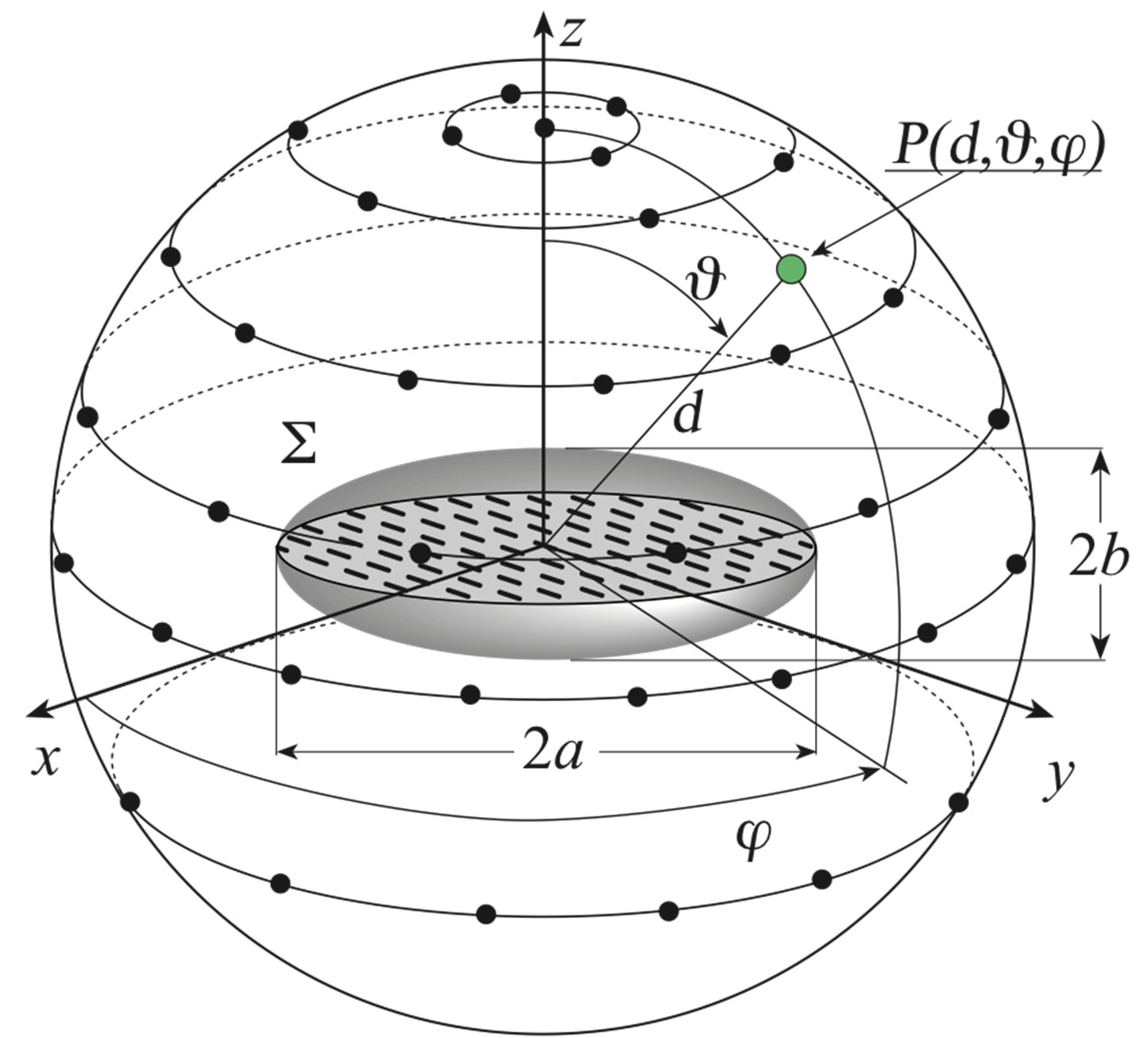
Figure 1. Spherical scanning for quasi-planar antennas.
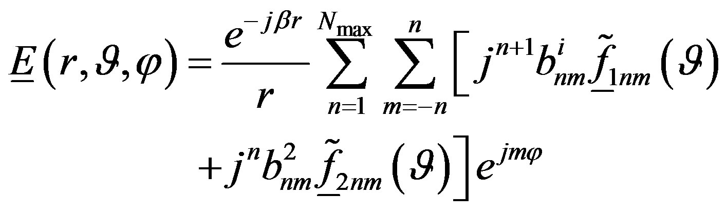
both in the NF and in the FF region (Figure 1). The tangential electric field in the FF region can be expressed via the truncated spherical wave expansion [12]:
 (1)
(1)
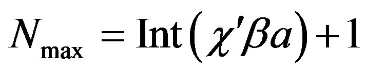
wherein the index of the highest spherical wave to be considered is rigorously fixed by the bandlimitation properties of the EM field and [13-15] is given by:
 (2)
(2)
where a is the radius of the smallest sphere enclosing the AUT, b is the wavenumber,  is the bandwidth enlargement factor, and Int(x) denotes the integer part of x. The vector wave functions
  are given by:
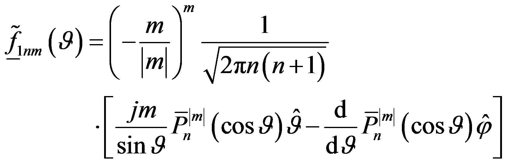 (3)
(3)
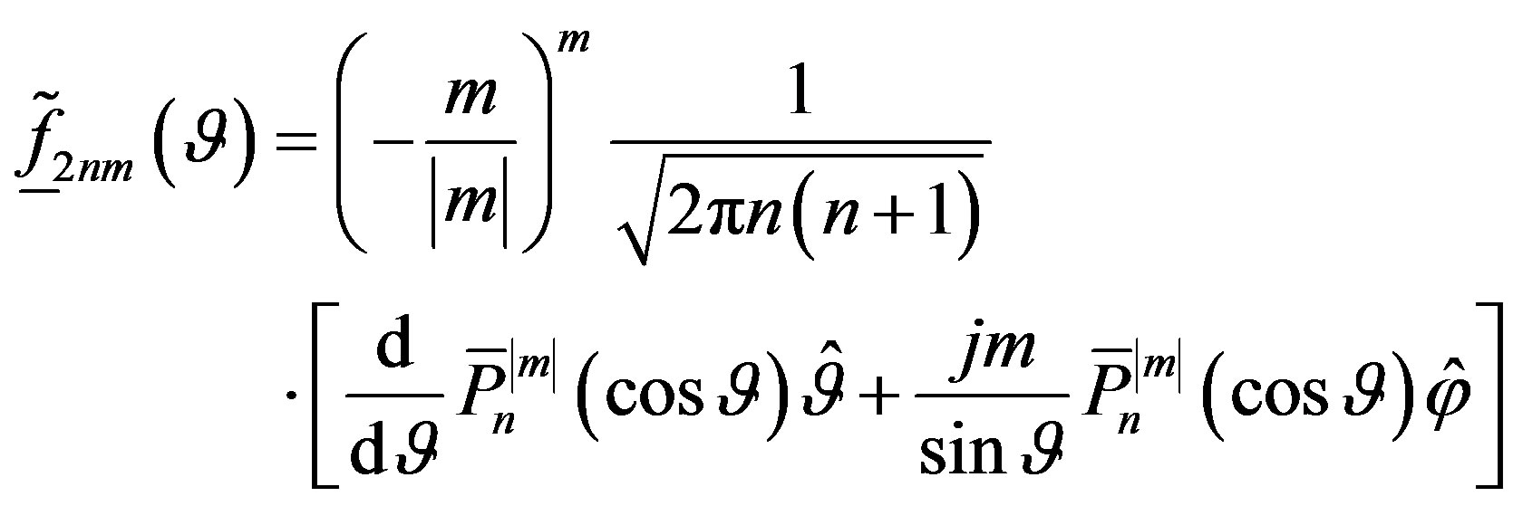 (4)
(4)
 being the normalized associated Legendre functions as defined in [29]. The spherical wave expansion coefficients
  and
and  are determined [14, 15] from the knowledge of the voltages
 ,
,  measured by the probe and rotated probe, respectively.
3. Nonredundant Voltage Representation on a Sphere
Let us consider a non directive probe scanning a spherecal surface of radius d in the NF region of a quasi-planar antenna enclosed in an oblate ellipsoid Σ having major and minor semi-axes equal to a and b (see Figure 1).
Since the voltage V measured by such a kind of probe has the same effective spatial bandwidth of the field [30], the nonredundant sampling representation of EM fields [18] can be applied to it. Inasmuch as the sphere can be represented by meridians and parallels, in the following we deal with the voltage representation on a curve C described by an optimal parameterization . According to [18], let us introduce the “reduced voltage”
 (5)
(5)
where  is the voltage measured by the probe or by the rotated probe, and
  is a proper phase function. The bandlimitation error, occurring when
  is approximated by a bandlimited function, becomes negligible as the spatial bandwidth exceeds a critical value
  [18] and can be effectively controlled by considering an enlarged bandwidth
 .
.
When C is a meridian, by choosing ,
,  being the length of the ellipse
  (intersection between the meridian plane through the observation point P and Σ), we get the following expressions [13] for the parameterization and phase function:
 (6)
(6)
 (7)
(7)
where  denotes the elliptic integral of second kind and
  and
and  are the elliptic coordinates,
  being the distances from P to the foci of the ellipse
 . Moreover,
  is its eccentricity and 2f its focal distance. The expression of the parameter
  in (6) is valid when the angle
  belongs to the range [0,
 ]. For
  ranging from
  to
to , it results
 , where
  is the parameterization value corresponding to the point specified by the angle
 . It is worthy to note that the curves γ = const and
  = const are ellipses and hyperbolas confocal to
  [18].
[18].
When the curve C is a parallel, the phase function  is constant and it is convenient to choose the angle
  as parameter. The corresponding bandwidth [13,18] is
 (8)
(8)
wherein  is the polar angle of the asymptote to the hyperbola through P.
According to these results, the voltage at P on the meridian fixed by  can be evaluated via the OSI expansion
 (9)
(9)
where  is the index of the sample nearest (on the left) to P, 2q is the number of retained intermediate samples
 ,
,
 (10)
(10)
 (11)
(11)
 is an oversampling factor required to control the truncation error [18], and
 (12)
(12)
Moreover,
 (13)
(13)
 (14)
(14)
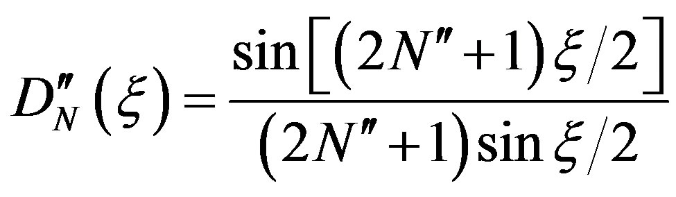
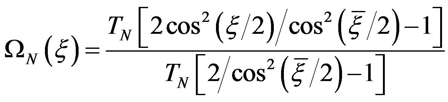
are the Dirichlet and Tschebyscheff sampling functions, respectively,  being the Tschebyscheff polynomial of degree
  and
and .
.
The intermediate samples on the meridian through P can be determined by means of a similar OSI expansion along . The two-dimensional OSI expansion for reconstructing the data at any point P on the sphere can be obtained [13] by properly matching the one-dimensional ones along the meridians and the parallels. Thus, we get:
 (15)
(15)
where in , 2p is the retained samples number along
 ,
,
 (16)
(16)
 (17)
(17)
 (18)
(18)
and the other symbols have the same meanings as in (9). The variation of  with
with  is required to ensure a bandlimitation error constant with respect to
 .
.
By using expansion (15), it is possible to evaluate the NF data needed by the classical NF - FF transformation with spherical scanning [12] as modified in [14,15].
4. From Nonuniform to Uniform Samples
Two different techniques to retrieve the uniformly distributed samples from the acquired irregularly spaced ones will be presented in this section and numerically compared in the subsequent one.
4.1. The SVD-Based Approach
The SVD-based approach can been applied when the starting two-dimensional problem of the uniform samples reconstruction can be reduced to find the solution of two independent one-dimensional problems. Accordingly, let us now suppose that, apart from the sample at the north pole, the irregularly distributed samples lie on nonuniformly spaced parallels. This assumption can really represent the spatial distribution of the measured data when the acquisition is carried out by moving along parallels, as required to exploit the possibility of reducing the number of NF data on noncentral parallels, offered by the described nonredundant representation.
Let us first consider the recovery of the uniformly spaced samples on each nonuniform parallel. Given a sequence of  known nonuniform sampling points
  on the nonuniform parallel at
  (where
  is the number of the corresponding uniform sampling points
 ), the known reduced voltage
  at each nonuniform sampling point can be expressed in terms of the unknown uniform samples via the OSI expansion along
 , thus getting the linear system:
 (19)
(19)
This last can be rewritten in the matrix form , where
  is the sequence
  of the known nonuniform samples, x is that of the unknown uniform ones
 , and
, and  is a
is a  matrix, whose elements are given by the weight functions in the considered OSI expansion:
 (20)
(20)
and, for any fixed row j, are equal to zero when the index m is out of the range . The best approximated solution in the least squares sense of the system
  is obtained by means of SVD.
Once the uniform samples on the nonuniform parallels have been so retrieved, the OSI expansion along  is used to determine the intermediate samples
  at the intersection points between the nonuniform parallels and the meridian passing through P. Obviously, these samples are again irregularly spaced and, accordingly, the voltage at P can be evaluated by first reconstructing the uniformly spaced intermediate samples via SVD and then interpolating them by using the OSI formula (9). It must be stressed that it is convenient to determine the same number of samples on each of the uniform parallels to minimize the computational effort. This number is that corresponding to the equator. In such a way, although the so retrieved NF data are slightly redundant in
 , the number of SVD relevant to the meridians is minimized. Once the uniform samples have been reconstructed, the NF data needed by the classical spherical NF - FF transformation [12] as modified in [14,15] can be determined via the OSI expansion (15), properly modified to take into account the redundancy in
 .
.
Note that, to avoid a strong ill-conditioning of the related linear system [24], both the displacements between the uniform and nonuniform samples on the nonuniform parallels and those between the uniform and nonuniform parallels must be such that to each uniform sampling position must correspond at least a nonuniform one whose distance is less than one half the uniform sampling spacing ( or
or ).
).
4.2. The Iterative Approach
When the hypothesis that the irregularly distributed samples lie on nonuniformly spaced parallels does not hold, the SVD technique could be still used, but the dimension of the involved matrix would become very large, thus requiring a massive computational effort. In fact, in such a hypothesis, the starting two-dimensional problem can no longer be tackled as two independent one-dimensional ones and it is more convenient to resort to the iterative technique [22,23]. Accordingly, let us assume in the following that, as required for the convergence of the iterative technique, the nonuniformly distributed samples are such that it is possible to build a biunique corresponddence, which associates at each uniform sampling point the “nearest” nonuniform one. In such a case, by expressing the reduced voltage at each nonuniform sampling point  as a function of the unknown values at the nearest uniform ones
  via the two-dimensional OSI expansion (15), we get:
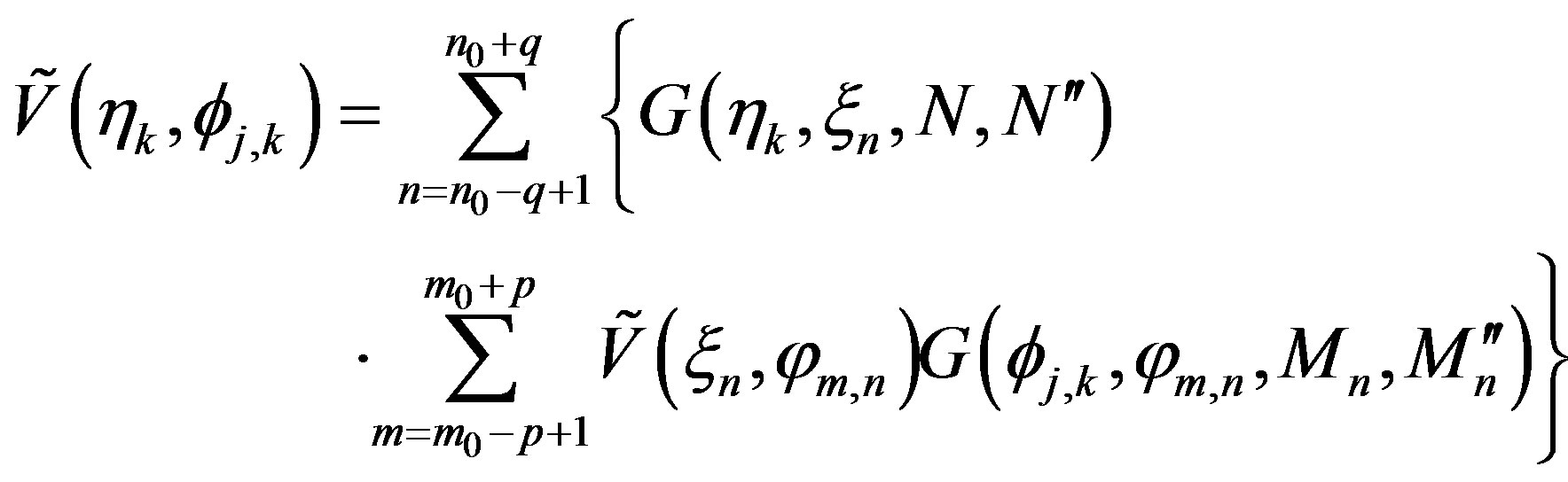 (21)
(21)
This last can be again rewritten as , where
  is a
is a  sparse banded matrix, whose elements are given by the weight functions in the considered OSI expansion (Q being the overall number of the nonuniform/uniform samples),
  is the sequence
  of the known irregularly distributed samples, and x is that of the unknown uniform ones
 .
.
By subdividing  into its diagonal part
  and nondiagonal one
 , multiplying both members of the matrix relation
  by
by  and rearranging the terms, we get:
 (22)
(22)
The following iterative scheme is so obtained:
 (23)
(23)
where  is the sequence of the uniform samples estimated at the
  step. Necessary conditions for the convergence of the above scheme are that the modulus of each element on the principal diagonal of
  be not zero and greater than those of the other elements on the same row and column [22,23]. These conditions are certainly verified in the assumed hypothesis of one-to-one correspondence between each uniform sampling point and the nearest nonuniform one.
By making (23) in explicit form, we finally get:
 (24)
(24)
The OSI expansion (15) is then used to interpolate the so recovered uniform NF samples for reconstructing the NF data needed to carry out the NF - FF transformation.
5. Numerical Tests
The numerical tests are relevant to a uniform planar circular array (see Figure 1) having diameter , where
  is the wavelength. Its elements are elementary Huygens sources polarized along the y axis and radially and azimuthally spaced by
 . Such an AUT has been modelled by an oblate ellipsoid with major and minor semi-axes equal to
  and
and , respectively. The scanning sphere has radius
  and an openended circular waveguide, having radius
 , is chosen as probe.
The first set of simulations (from Figures 2-9) refers to the case of irregularly spaced samples lying on nonuniformly distributed parallels, so that the reconstruction of the uniform samples can be reduced to the solution of two independent one-dimensional problems. The nonuniform samples (whose positions are assumed
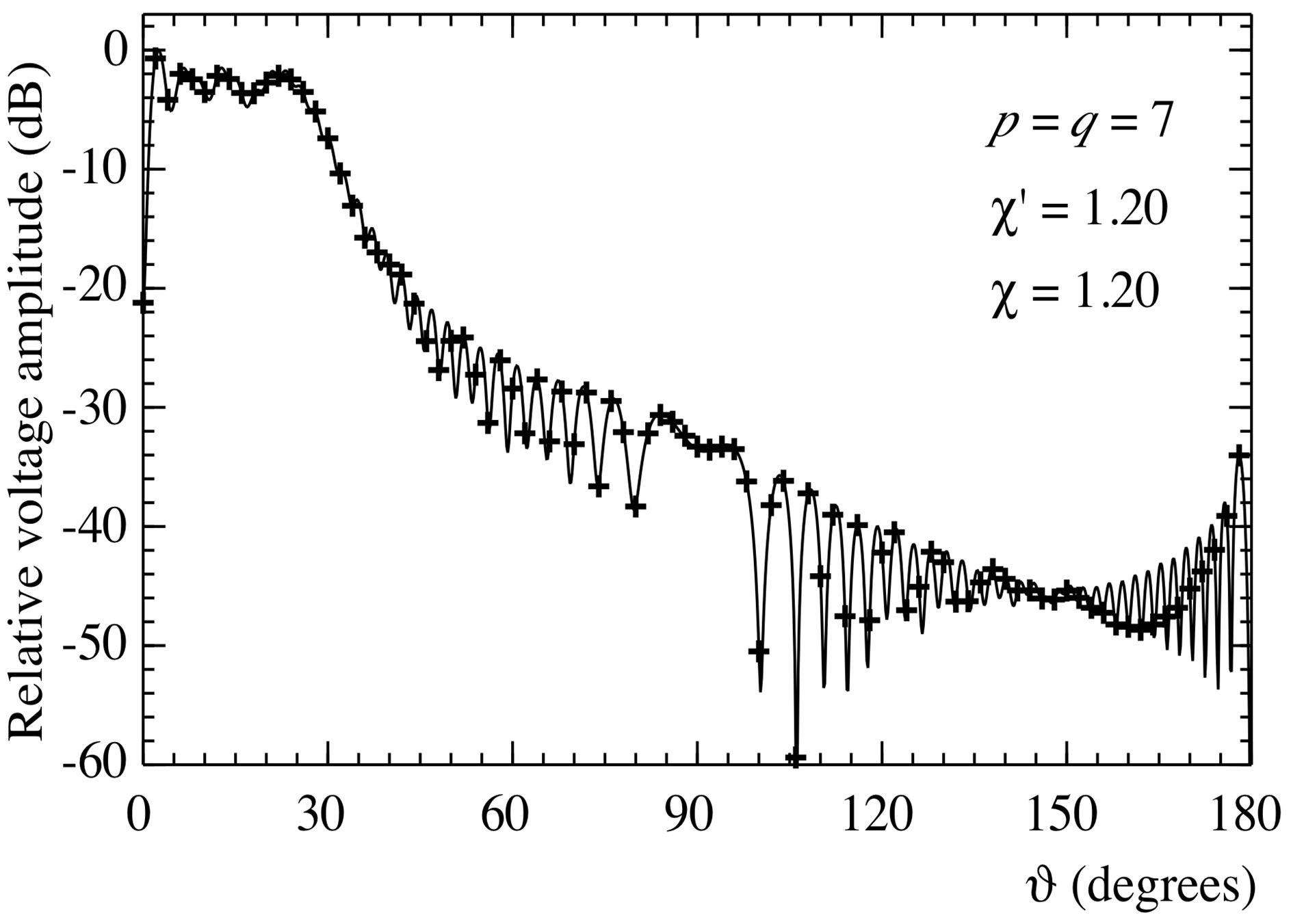
Figure 2. Amplitude of the probe voltage V2 on the meridian at φ = 90˚. Solid line: exact. Crosses: reconstructed from nonuniform samples via the SVD-based algorithm.
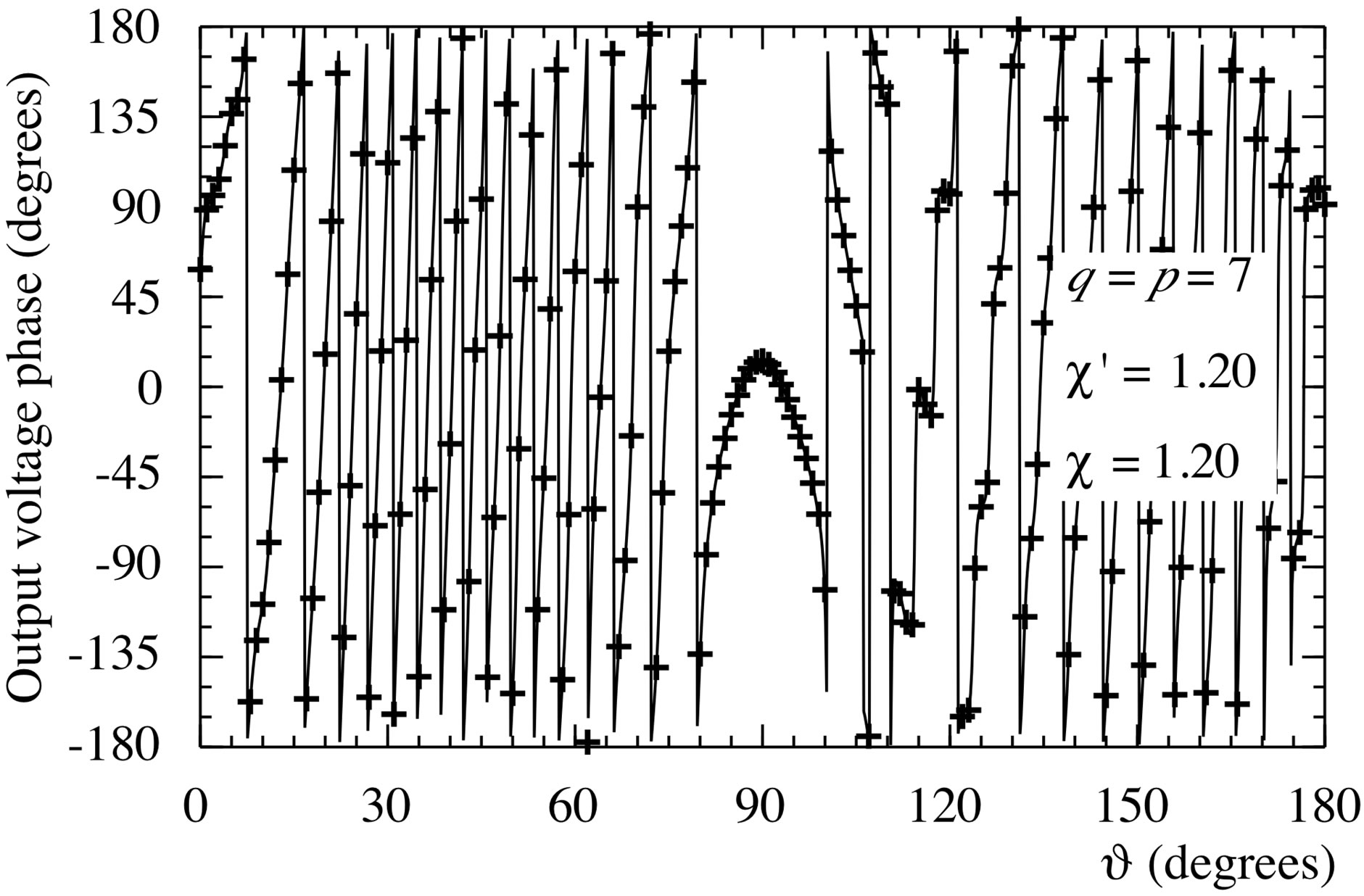
Figure 3. Phase of the probe voltage V2 on the meridian at φ = 90˚. Solid line: exact. Crosses: reconstructed from nonuniform samples via the SVD-based algorithm.
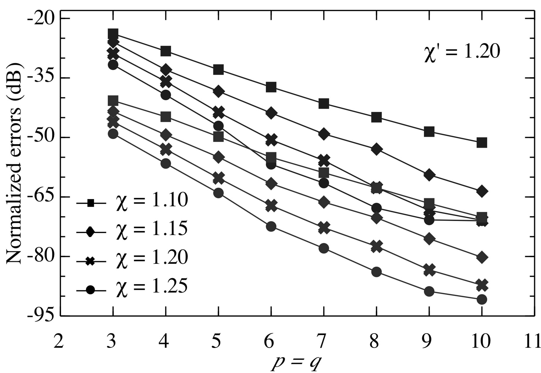
Figure 4. Normalized maximum (blue lines) and meansquare (red lines) errors in the reconstruction of the uniform samples of V2 via the SVD-based algorithm.

Figure 5. Amplitude of the voltage V2 on the meridian at φ = 90˚. Solid line: exact. Crosses: reconstructed from error affected nonuniform samples via the SVD-based algorithm.
known) have been generated by imposing that the distance between the position of each of these parallels and the associated uniform one is a random variable uniformly distributed in . Similarly, the dis-
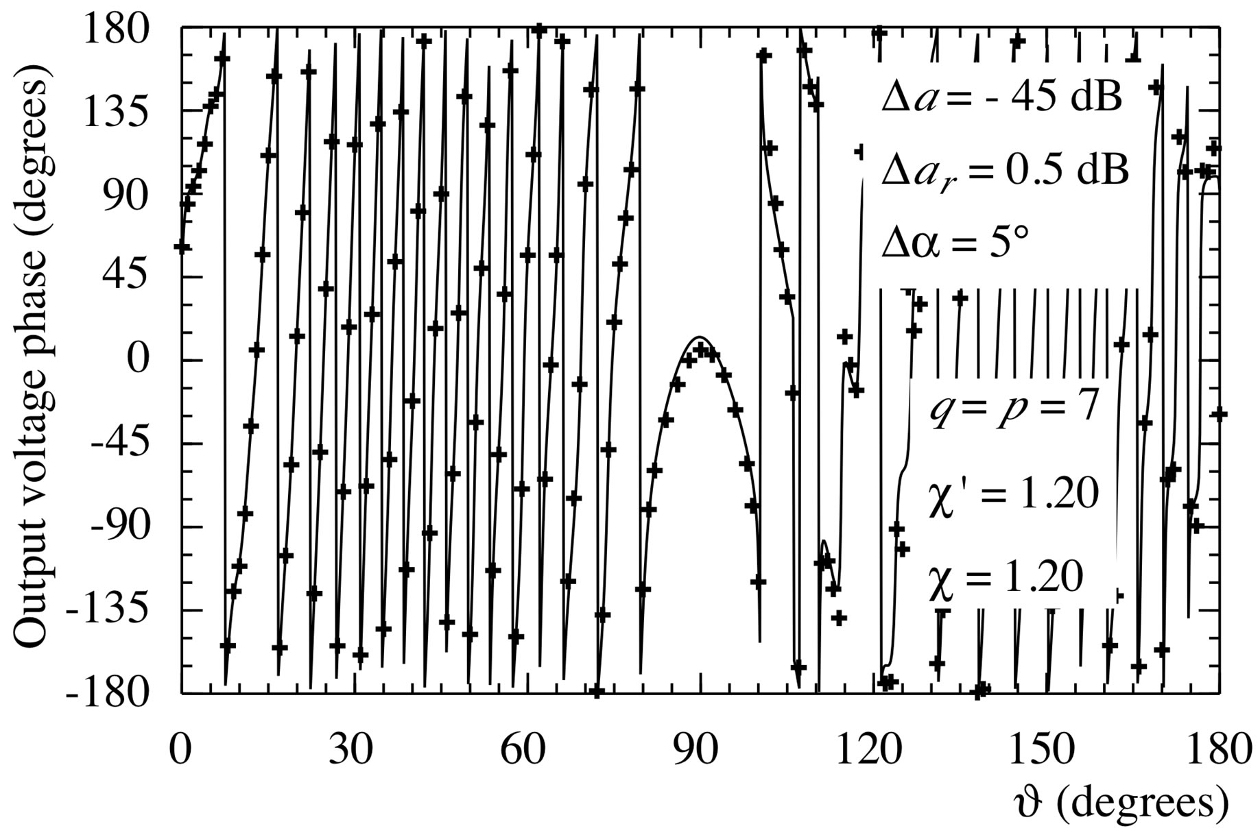
Figure 6. Phase of the probe voltage V2 on the meridian at φ = 90˚. Solid line: exact. Crosses: reconstructed from nonuniform samples via the SVD-based algorithm.
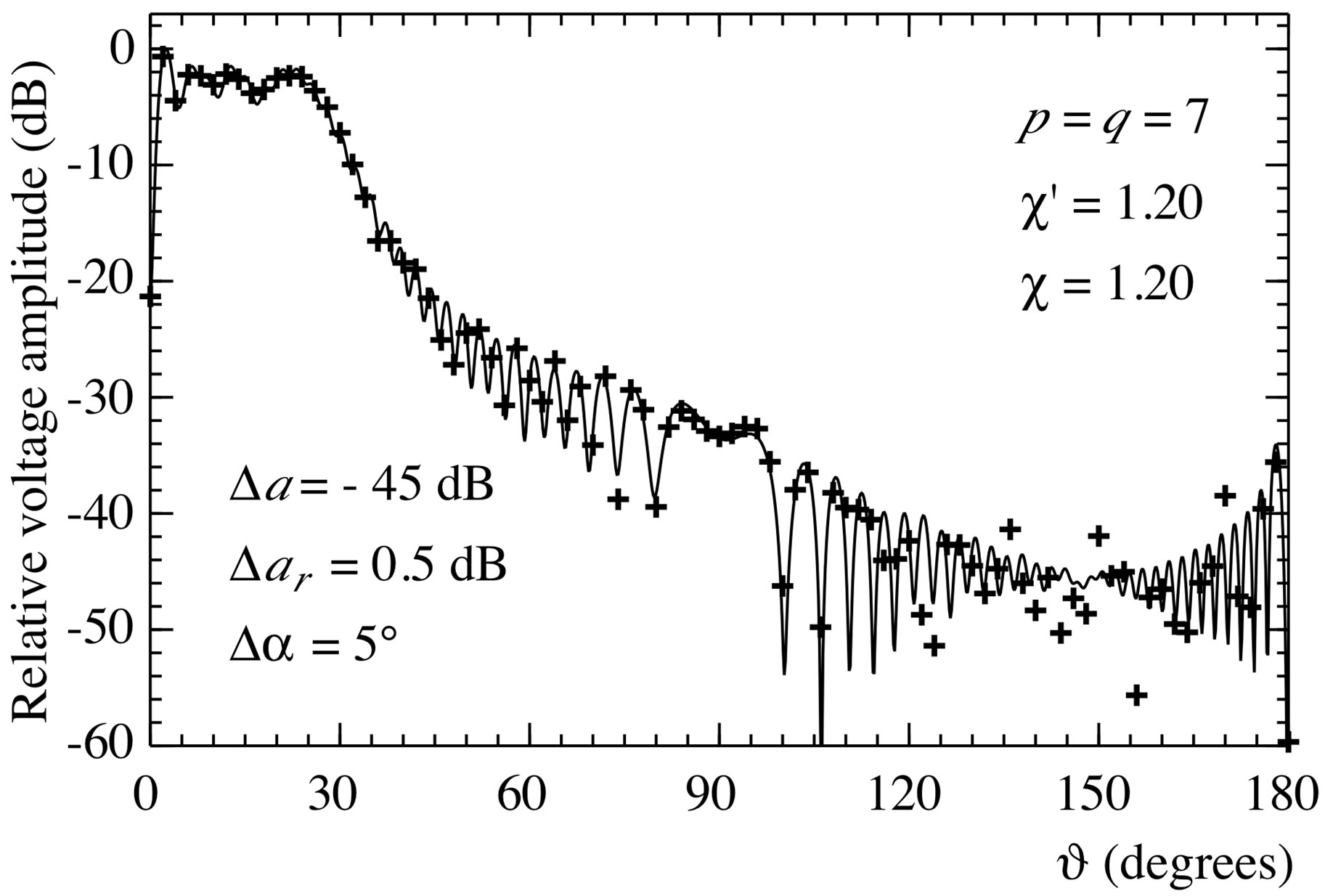
Figure 7. Amplitude of the voltage V2 on the meridian at φ = 90˚. Solid line: exact. Crosses: reconstructed from error affected nonuniform samples (increased by 20%) via the SVD-based algorithm.
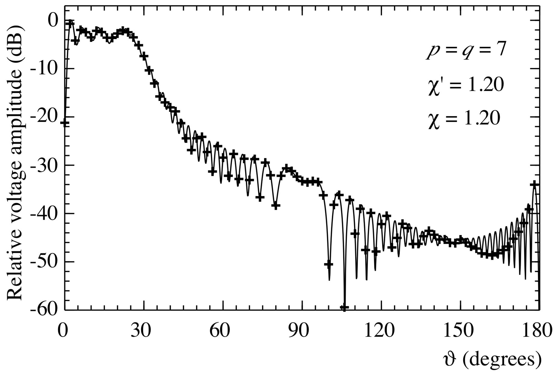
Figure 8. Amplitude of the probe voltage V2 on the meridian at φ = 90˚. Solid line: exact. Crosses: reconstructed from nonuniform samples via the iterative algorithm.
placements between the irregularly spaced sampling points and the corresponding regularly spaced ones on the nonuniform parallels are random variables uniformly distributed in . The reconstructed am-

Figure 9. E-plane pattern. Solid line: exact. Crosses: reconstructed from nonuniform samples via the SVD-based algorithm.
plitude and phase of the rotated probe voltage  (the most significant one) on the meridian at
  90˚ are shown in Figures 2 and 3. As can be seen, the exact and reconstructed curves are indistinguishable in spite of the considered large values of the probe positioning errors, very pessimistic in an actual scanning procedure. The performances of the SVD algorithm for compensating the positioning errors have been assessed in a more quantitative way by evaluating the maximum and mean-square errors in the reconstruction of the uniform samples. They are normalized to the voltage maximum value on the sphere and have been obtained by comparing the reconstructed and the exact uniform samples. As can be seen from Figure 4, they decrease up to very low values on increasing the number of retained samples and/or the oversampling factor. Even smaller errors are to be expected when the irregularly spaced samples are nearer to the uniform ones [28]. The robustness of algorithm with respect to errors affecting the data has been assessed (see Figures 5 and 6) by corrupting the exact samples with random errors. These errors simulate a background noise (bounded to
  in amplitude and with arbitrary phase) and uncertainties on the data of
  in amplitude and
  in phase. As already stated, the algorithm stability can be improved (see Figure 7) by taking advantage of the redundancy to filter the errors affecting the data. The same irregularly spaced NF data set used in Figure 2 has been employed to recover the voltage
  on the meridian at
  via the iterative algorithm. As can be seen, the reconstruction (see Figure 8) obtained after 5 iterations coincides with the one achieved by means of the SVD approach. The SVD-based procedure for compensating the positioning errors has been finally applied to efficiently recover the NF data needed to carry out the NF - FF transformation. The reconstructed FF pattern in the principal plane E is compared with the exact one in Figure 9. As can be seen, the exact and recovered patterns are indistinguishable, thus confirming the effectiveness of the approach. Identical results are obtained when the NF data needed to perform the NF - FF transformation are recovered from the same nonuniform NF data set via the iterative technique.
The second set of simulations (from Figures 10-14) refers to the case of irregularly spaced samples that do not lie on parallels. In such a situation, it is more convenient, from the computational viewpoint, to apply the iterative approach, that requires the existence of a one-to-one correspondence between the uniform and nonuniform samples, associating at each uniform sampling point the nearest irregular one. Accordingly, the irregularly distributed samples have been generated in such a way that the displacements in  and
and  between each nonuniform sampling point and the corresponding uniform one are random variables uniformly distributed in
  and
and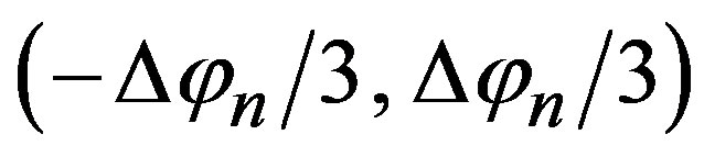 . The reconstructions of the amplitude and phase of the probe voltage
  obtained after 5 iterations are shown in Figures 10 and 11. The normalized maximum and mean-square errors in the reconstruction of the uniform
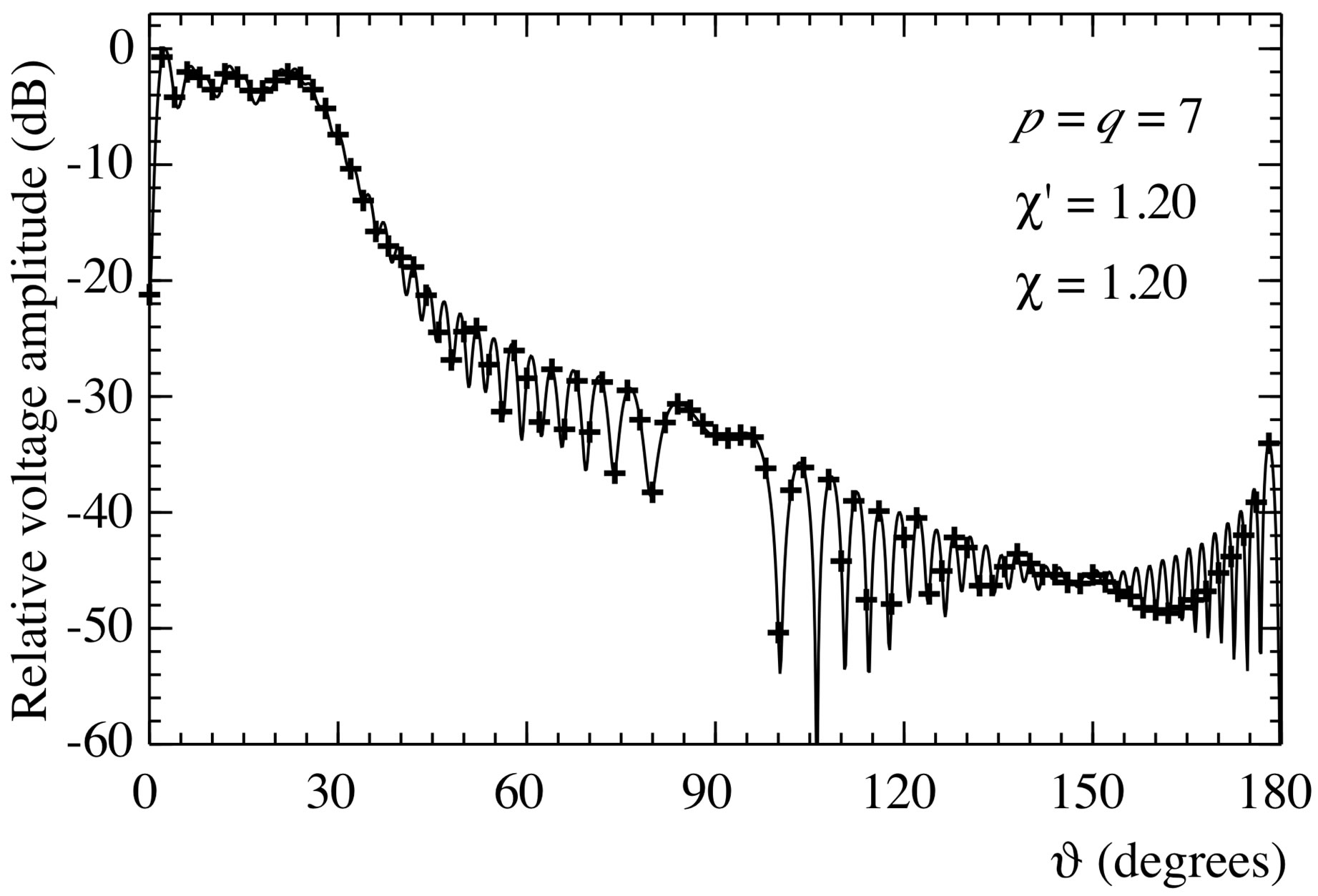
Figure 10. Amplitude of the probe voltage V2 on the meridian at φ = 90˚. Solid line: exact. Crosses: reconstructed from nonuniform samples via the iterative algorithm.
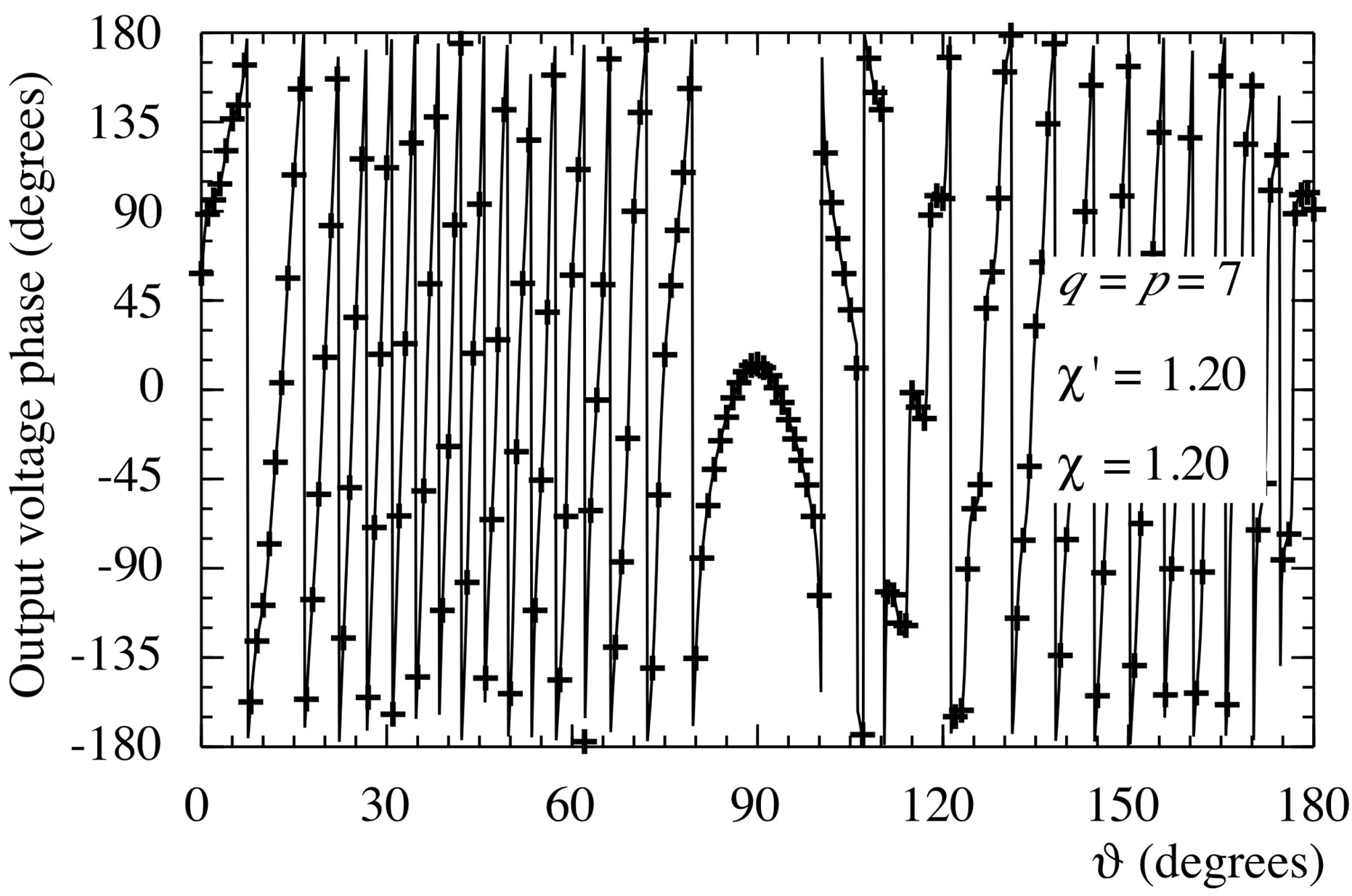
Figure 11. Phase of the probe voltage V2 on the meridian at φ = 90˚. Solid line: exact. Crosses: reconstructed from nonuniform samples via the iterative algorithm.
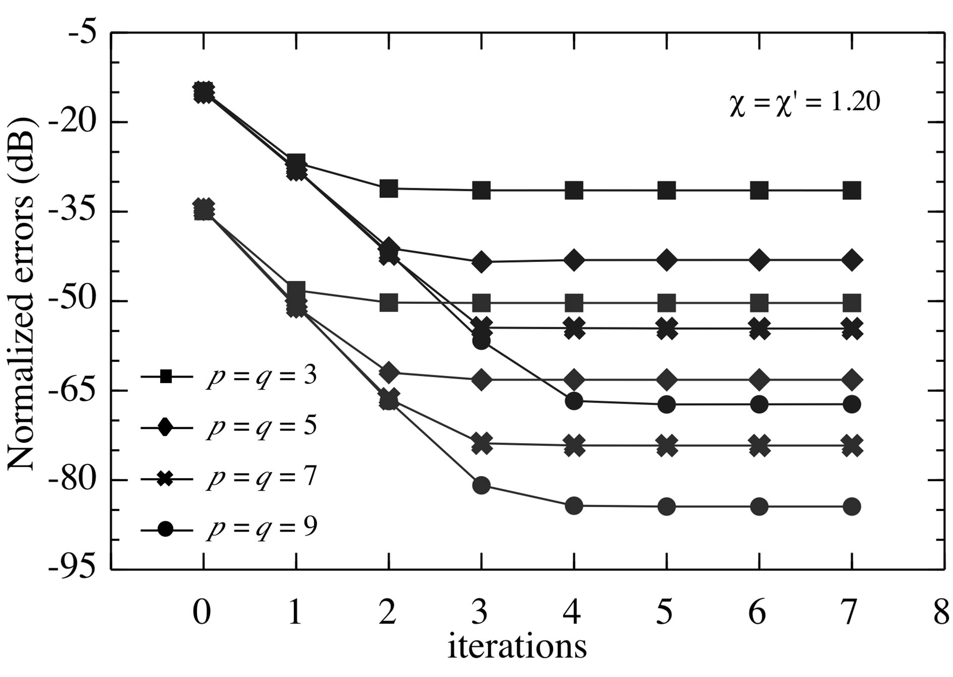
Figure 12. Normalized maximum (blue lines) and meansquare (red lines) errors in the reconstruction of the uniform samples of V2 via the iterative algorithm.
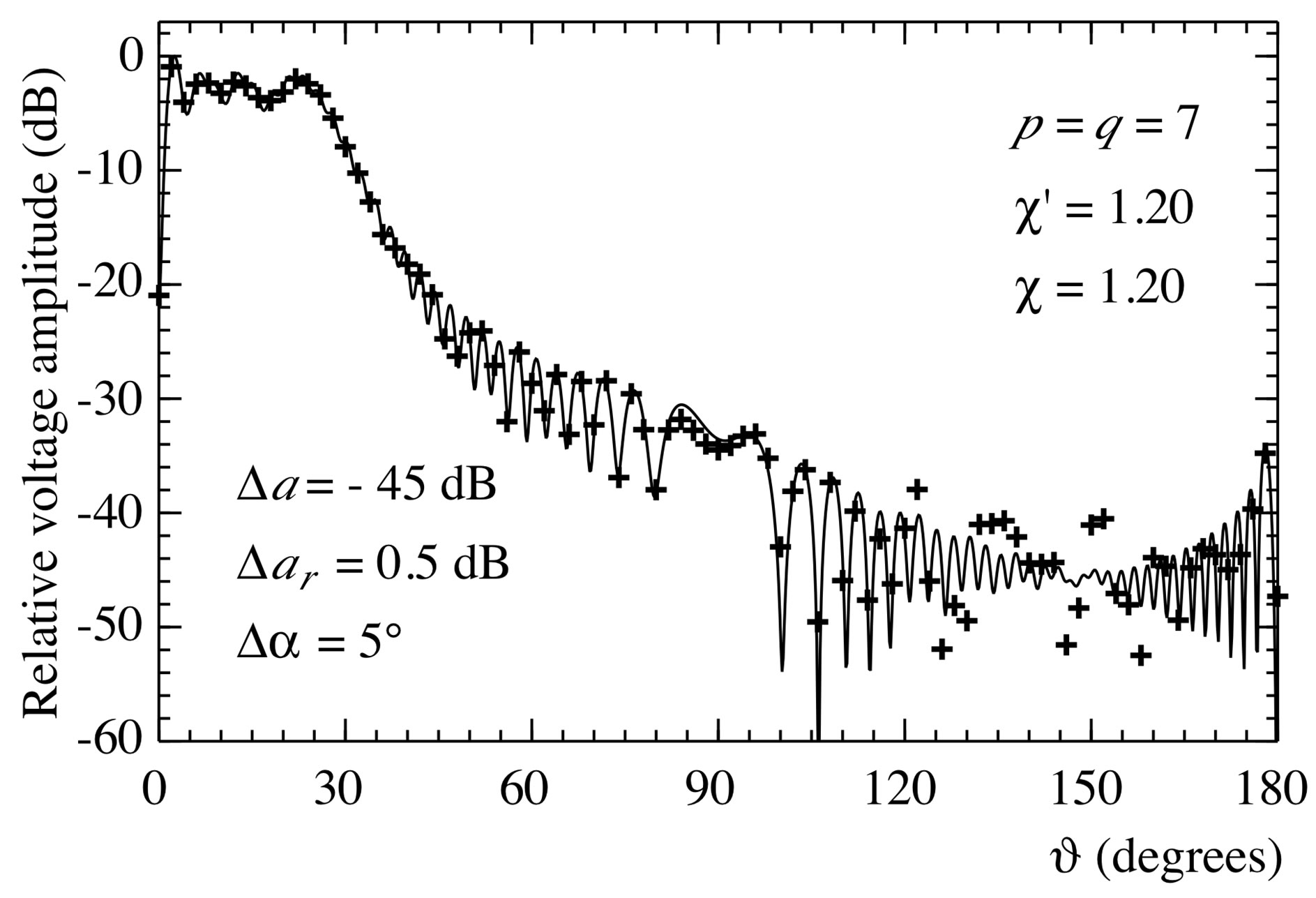
Figure 13. Amplitude of the voltage V2 on the meridian at φ = 90˚. Solid line: exact. Crosses: reconstructed from error affected nonuniform samples via the iterative algorithm.

Figure 14. E-plane pattern. Solid line: exact. Crosses: reconstructed from nonuniform samples via the iterative algorithm.
samples are reported in Figure 12 in order to assess more quantitatively the effectiveness of the iterative approach and to give an insight on the number of iterations and retained samples needed to assure the desired accuracy. Its capability to work well also in presence of errors affecting the data is shown in Figure 13. At last, the overall effectiveness is confirmed by the very good far-field reconstruction displayed in Figure 14.
For sake of completeness, we stress that the reported results have been obtained by using 15,986 NF samples, which are remarkably lower than those (32,514) required by the classical NF - FF transformation with spherical scanning [12].
6. Conclusion
The compensation of known positioning errors in the NF - FF transformation with spherical scanning for quasiplanar antennas has been tackled in this paper. To this end, two different techniques to evaluate the uniformly distributed spherical samples from the nonuniform ones have been developed and numerically compared. The former uses the SVD method and can be conveniently employed when the nonuniform sampling points lie on parallels. The latter employs an iterative algorithm and can be applied also when the nonuniform sampling points do not lie on parallels, but requires the existence of a biunique correspondence that associates at each uniform sampling point the nearest irregular one. The reported numerical results assess the accuracy and robustness of both approaches in spite of the considered large values of the probe positioning errors, very pessimistic in an actual scanning procedure.
REFERENCES
- A. D. Yaghjian, “An Overview of Near-Field Antenna Measurements,” IEEE Transactions on Antennas and Propagation, Vol. 34, No. 1, 1986, pp. 30-45. doi:10.1109/TAP.1986.1143727
- IEEE Antennas and Propagation Society, “Special Issue on Near-Field Scanning Techniques,” IEEE Transactions on Antennas and Propagation, Vol. 36, No. 6, 1988, pp. 727-901.
- D. Slater, “Near-Field Antenna Measurements,” Artech House, Boston, 1991.
- C. Gennarelli, G. Riccio, F. D’Agostino and F. Ferrara, “Near-Field - Far-Field Transformation Techniques,” CUES, Salerno, 2004.
- C. A. Balanis, “Modern Antenna Handbook,” John Wiley & Sons, Inc., Hoboken, 2008. doi:10.1002/9780470294154
- R. G. Yaccarino, Y. R. Samii and L. I. Williams, “The BiPolar Planar Near-Field Measurement Technique, Part II: Near-Field to Far-Field Transformation and Holographic Imaging Methods,” IEEE Transactions on Antennas and Propagation, Vol. 42, No. 2, 1994, pp. 196-204. doi:10.1109/8.277213
- P. F. Wacker, “Non-Planar Near-Field Measurements: Spherical Scanning,” National Bureau of Standards, Boulder, 1975.
- F. H. Larsen, “Probe Correction of Spherical Near-Field Measurements,” Electronic Letters, Vol. 13, No. 14, 1977, pp. 393-395. doi:10.1049/el:19770287
- F. H. Larsen, “Probe-Corrected Spherical Near-Field Antenna Measurements,” Ph.D. Dissertation, Technical University of Denmark, Copenhagen, 1980.
- A. D. Yaghjian and R. C. Wittmann, “The Receiving Antenna as a Linear Differential Operator: Application to Spherical Near-Field Measurements,” IEEE Transactions on Antennas and Propagation, Vol. 33, No. 11, 1985, pp. 1175-1185. doi:10.1109/TAP.1985.1143520
- J. E. Hansen and F. Jensen, “Spherical Near-Field Scanning at the Technical University of Denmark,” IEEE Transactions on Antennas and Propagation, Vol. 36, No. 6, 1988, pp. 734-739. doi:10.1109/8.1174
- J. Hald, J. E. Hansen, F. Jensen and F. H. Larsen, “Spherical Near-Field Antenna Measurements,” In: J. E. Hansen, Ed., IEEE Electromagnetic Waves Series, Peter Peregrinus, London, 1998.
- O. M. Bucci, F. D’Agostino, C. Gennarelli, G. Riccio and C. Savarese, “Data Reduction in the NF - FF Transformation Technique with Spherical Scanning,” Journal of Electromagnetic Waves and Applications, Vol. 15, No. 6, 2001, pp. 755-775. doi:10.1163/156939301X00995
- A. Arena, F. D’Agostino, C. Gennarelli and G. Riccio, “Probe Compensated NF - FF Transformation with Spherical Scanning from a Minimum Number of Data,” Atti Della Fondazione Giorgio Ronchi, Vol. 59, No. 3, 2004, pp. 312-326.
- F. D’Agostino, F. Ferrara, C. Gennarelli, R. Guerriero and M. Migliozzi, “Effective Antenna Modellings for a NF-FF Transformation with Spherical Scanning Using the Minimum Number of Data,” International Journal of Antennas and Propagation, Vol. 2011, Article ID 936781. doi:10.1155/2011/936781
- T. B. Hansen, “Higher-Order Probes in Spherical NearField Scanning,” IEEE Transactions on Antennas and Propagation, Vol. 59, No. 11, 2011, pp. 4049-4059. doi:10.1109/TAP.2011.2164217
- O. M. Bucci and G. Franceschetti, “On the Spatial Bandwidth of Scattered Fields,” IEEE Transactions on Antennas and Propagation, Vol. 35, No. 12, 1987, pp. 1445- 1455. doi:10.1109/TAP.1987.1144024
- O. M. Bucci, C. Gennarelli and C. Savarese, “Representation of Electromagnetic Fields over Arbitrary Surfaces by a Finite and Nonredundant Number of Samples,” IEEE Transactions on Antennas and Propagation, Vol. 46, No. 3, 1998, pp. 351-359. doi:10.1109/8.662654
- A. Dutt and V. Rohklin, “Fast Fourier Transforms for Non Equispaced Data,” Proceedings of SIAM Journal Scientific Computation, Vol. 14, No. 6, 1993, pp. 1369- 1393.
- R. C. Wittmann, B. K. Alpert and M. H. Francis, “NearField Antenna Measurements Using Nonideal Measurement Locations,” IEEE Transactions on Antennas and Propagation, Vol. 46, No. 5, 1998, pp. 716-722. doi:10.1109/8.668916
- R. C. Wittmann, B. K. Alpert and M. H. Francis, “NearField, Spherical Scanning Antenna Measurements with Nonideal Probe Locations,” IEEE Transactions on Antennas and Propagation, Vol. 52, No. 8, 2004, pp. 2184- 2186. doi:10.1109/TAP.2004.832316
- O. M. Bucci, C. Gennarelli and C. Savarese, “Interpolation of Electromagnetic Radiated Fields over a Plane from Nonuniform Samples,” IEEE Transactions on Antennas and Propagation, Vol. 41, No. 11, 1993, pp. 1501-1508. doi:10.1109/8.267349
- O. M. Bucci, C. Gennarelli, G. Riccio and C. Savarese, “Electromagnetic Fields Interpolation from Nonuniform Samples over Spherical and Cylindrical Surfaces,” IEEE Proceedings Microwaves Antennas Propagation, Vol. 141, No. 2, 1994, pp. 77-84. doi:10.1049/ip-map:19949838
- F. Ferrara, C. Gennarelli, G .Riccio and C. Savarese, “Far Field Reconstruction from Nonuniform Plane-Polar Data: A SVD Based Approach,” Electromagnetics, Vol. 23, No. 5, 2003, pp. 417-429. doi:10.1080/02726340390203171
- F. Ferrara, C. Gennarelli, G. Riccio and C. Savarese, “NFFF Transformation with Cylindrical Scanning from Nonuniformly Distributed Data,” Microwave and Optical Technology Letters, Vol. 39, No. 1, 2003, pp. 4-8. doi:10.1002/mop.11109
- G. H. Golub and C. F. Van Loan, “Matrix Computations,” The Johns Hopkins University Press, Baltimore, 1996.
- F. D’Agostino, F. Ferrara, C. Gennarelli, R. Guerriero and M. Migliozzi, “On the Compensation of Probe Positioning Errors When Using a Nonredundant Cylindrical NF - FF Transformation,” Progress in Electromagnetics Research B, Vol. 20, 2010, pp. 321-335. doi:10.2528/PIERB10032402
- F. D’Agostino, F. Ferrara, C. Gennarelli, R. Guerriero, and M. Migliozzi, “Two Techniques for Compensating the Probe Positioning Errors in the Spherical NF-FF Transformation for Elongated Antennas,” The Open Electrical & Electronic Engineering Journal, Vol. 5, 2011, pp. 29-36. doi:10.2174/1874129001105010029
- S. L. Belousov, “Tables of Normalized Associated Legendre Polynomials,” Pergamon Press, Oxford, 1962.
- O. M. Bucci, G. D’Elia and M. D. Migliore, “Advanced Field Interpolation from Plane-Polar Samples: Experimental Verification,” IEEE Transactions on Antennas and Propagation, Vol. 46, No. 2, 1998, pp. 204-210. doi:10.1109/8.660964