Journal of Electromagnetic Analysis and Applications
Vol. 3 No. 10 (2011) , Article ID: 8141 , 4 pages DOI:10.4236/jemaa.2011.310062
A Novel Approach in RF-MEMS Switch Analysis Using Time Domain TLM Method
![]()
1Department of Electrical and Electronic Engineering, Urmia University, Urmia, Iran; 2Islamic Azad University, Urmia Branch, Urmia, Iran.
Email: davod.ahmadian@gmail.com
Received July 18th, 2011; revised August 20th, 2011; accepted September 2nd, 2011.
Keywords: Transmission Line Matrix, Micro Electromechanical System, Switch Analyze
ABSTRACT
In this paper the transmission line matrix (TLM) method is exploited to evaluate the electromagnetic field distribution over a new radio frequency micro electromechanical system (RF-MEMS). A hybrid symmetrical condensed node is used to analyze S-parameters of the switch in on and off states. Furthermore, the effects of spring zigzag cuts over the bridge are analyzed. Results have authorized that TLM method offers a much faster and more reliable results compare to other numerical methods because of its time domain behavior and transmission line basis.
1. Introduction
Recently, transmission line matrix method is widely used to solve electromagnetic problems [1-9]. This method utilizes voltage and current concepts to satisfy Maxwell’s equations and distinguish field distributions over desired environment. This method has a range of unique characteristics which make it clear to grasp and easy to apply.
Most of earlier works on TLM were done to organize novel nodes and stubs taking care of material properties implementation, simple and symmetrical forms (of nodes), and finally easy connection to other nodes and boundaries.
In [3], TLM method has been used to simulate the wave propagation through window structures in EMC applications. Jin et al. [5] presented some derivations of the TLM symmetrical and hybrid symmetrical condensed nodes by using central differencing and averaging. The scattering matrices and field expressions were given for both uniform and graded meshes. The node which has thereby been described, easily accounts for anisotropic materials, and electric and magnetic losses with second order accuracy. In a work done by Zhizhang et al. [7], the time and frequency domain TLM methods have been developed and their relationship has been described using the discrete time and inverse discrete time Fourier transform. This paper has also declared that, the choice of using the frequency or time domain TLM extremely depends on the types of the problems and user’s trends. In
[8], Frye et al. present an extrapolation technique which claimed to reduce the computational time and memory usage in wideband electromagnetic problems for antennas and propagations by using genetic algorithm. It has been shown that “a wideband response can be extrapolated by fitting data with a summation of orthogonal polynomials”. However, this method in practice is computationally inefficient and can lead to numerical instabilities.
Miniaturization has been the foremost technological tendency during the past decades and in this global trend; miniaturization of the Micro-Electromechanical Systems (MEMS) has become one of the most scholar research areas all over the world. The major problem in RFMEMS technology is the amount of DC voltage which has to be applied to excite electrostatic force and bend the bridge. By development of the Micro and MEMS technologies, many authors tried different methods and ideas to overcome the situation and decrease the required DC voltage. In [10,11], utilize a Koch fractal beam instead of the traditional rectangular ones improve the bending momentum and force/stiffness ratio of the membrane.
In this paper, a new numerical approach is used to evaluate the novel advanced technology of RF-MEMS switch. Here, we reveal that by TLM method are compared with finite element method and measured results in [9], TLM curves show a better fit to the measured values especially in case of return loss and insertion loss. Also using cuts over the bridge actuation DC voltage is decreased as decreasing of its spring constant.
2. Theory and Design
2.1. TLM Theory
The topology of the TLM scheme with the expanded node is similar to that of the finite difference time-domain (FDTD) scheme of Yee. Developments in both 2D and 3D TLM schemes, based on varying the characteristic impedance e of link lines and introducing hybrid nodes, have resulted in a more efficient implementation of the variable graded mesh and a better modeling of general materials, compared to the original nodes. Recently, time domain (TD) TLM schemes for efficiently solving field problems have been developed from similar principles.
The TLM method consists of four basic steps includeing excitation, scattering, connection, and boundary condition. The trait of all time domain numerical methods is that the wide frequency domain response has no effect on the simulation duration. This characteristic makes these methods quite suitable for wideband MEMS switch and phase shifter analysis.
These steps and specifications are gathered together in a computer code which uses HSCN nodes in Visual C++ environment uses both types of absorbing condition and perfect match layer (PML) to simulate wave propagation in open boundaries. The PML layers are recommended here to have reflection coefficient and intrinsic impedance of the form, as following:
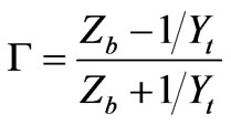 (1)
(1)
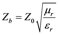 (2)
(2)
where Yt is the characteristic admittance of the transmission line, and Z0 is 377 Ω (intrinsic impedance of the free space). ∆l is the smallest dimension of the block where the mesh is spaced in model. By increasing the number of spatial divisions, the cell size decreases and this causes a dispersion error which mostly shows itself as a high frequency noise. To avoid this noise, a low pass filter (LPF) has to be convolved with the original results. The impulse response of a LPF with cutoff frequency of f1 is:
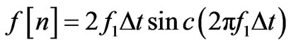 (3)
(3)
where ∆t is the stable time step of TLM method. This parameter controls both convergence speed and stability.
2.2. RF MEMS Switch Design
The geometry and dimensions of a RF-MEMS switch is presented in Figure 1 and Table 1. A typical RF-MEMS switch consists of a coplanar waveguide (CPW) with g/w/g dimensions mounted over a silicon substrate with εr = 11.9 and adjusted to have 50 Ω characteristic impedance over the desired frequency range.
A metal bridge is then established to cross the central conductor of the CPW, connecting two separate sides of the ground plane. By applying a constant DC voltage to the central conductor of CPW, an electrostatic force excites between bridge and the central conductor. This force bends the bridge along its length to touch the opposite pole. So, a thin (td) layer of insulator (SiO2) has to be deposited over the central conductor to avoid any direct touch between metals of opposite charges. Curved bridge is then suppresses RF wave from passing through and returns it back to the source. Then zero, 2nd, 3rd order symmetrical cuts over the bridge to decrease the spring constant are used, as shown in Figure 2.
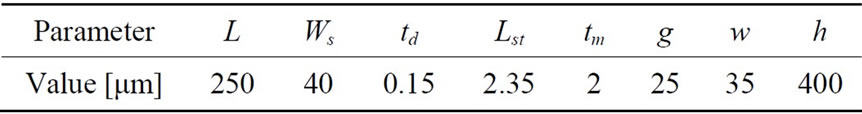
Table 1. Typical RF-MEMS switch dimensions.
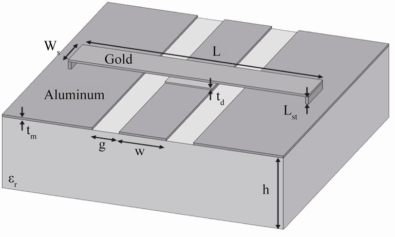
Figure 1. RF-MEMS switch profile and geometry.
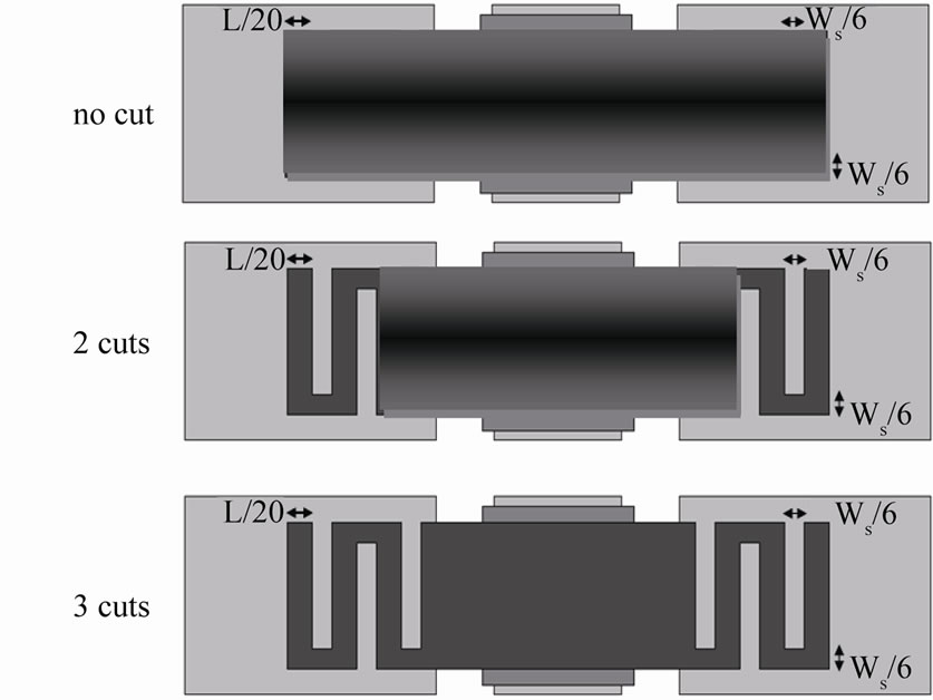
Figure 2. Zero, two, three symmetrical cuts over the bridge to decrease the spring constant.
3. Results and Discussions
3.1. Comparison between TLM and FEM
In Figures 3 and 4, the insertion loss (S21) and return loss (S11) results of the rectangular MEMS switch by TLM method are compared with finite element method and measured values that obtained in [9] are presented in up and down states, respectively. In [9], the finite element results are calculated using Ansoft HFSS v10. When the switch turns off (up state), the insertion loss and return loss remains less than −3.7 dB and −28 dB, respectively. When, it turns entirely on, insertion loss increases to −15 dB and return loss decreases to −3 dB. From the Figure 3 and 4, very good agreement between TLM results and measured results compare to FEM results is observed.
3.2. Effects of Three Types of Cuts on Switch Performance
In order to investigation the effect of the different type of
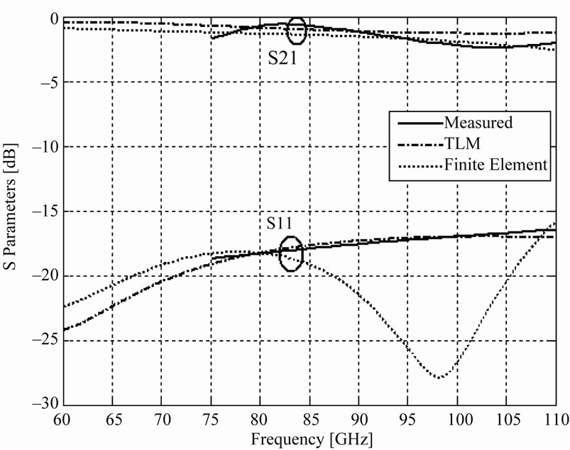
Figure 3. S-parameters of the MEMS switch in up state.
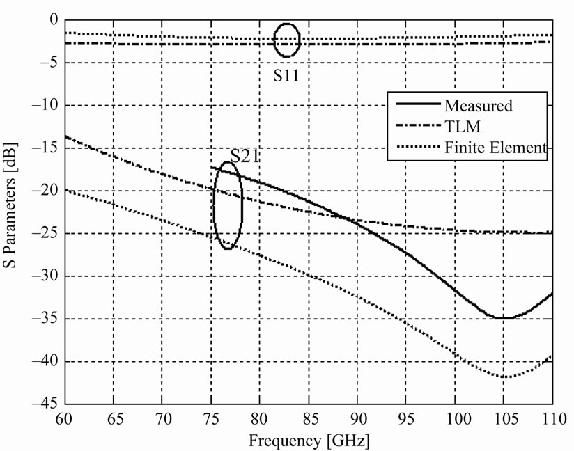
Figure 4. S-parameters of the MEMS switch in down state.
cuts on the RF-MEMS switch performance, three type of symmetrical cuts over the bridge as shown in Figure 2 are chosen as follows: no cuts; two symmetric cuts; two symmetric cuts. There are many relevant equations for spring constant (K) and pull-down voltage (V) of MEMS switch. Given that the width of beam is L/20, the width of the pull-down plate is nWs/6 and E is the electric field due to the applied voltage as shown in Figure 2, the K and V are
 (3)
(3)
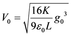 (4)
(4)
where g0 is the zero-bias bridge height and n is number of symmetric cut. From the Equations (3) and (4), it is observed that by increasing of number of cuts (n), the spring constant (K) is decreased and therefore the pulldown voltage (V) is decreased. On the other hand, the TLM method is used in Figures 5 and 6 to evaluate the effect of these cuts on S-parameters. Figure 5 is plotted in upstate and compares no cut with 2 and 3 symmetrical cuts. It is obvious that these cuts have a minor effect on the results. The effect of 2 and 3 symmetrical cuts in down state of the switch were studied in Figure 6. Despite the fact that these cuts did not affect the S-parameters in upstate, but they evidently have influence on return loss when the switch is turned on. According to the insertion loss (S21) and return loss (S11) results of in Figures 5 and 6, when the number of cuts (n) increases, the performance of switch is small ruined. Therefore we choose three symmetric cuts on switch as a optimize design.
4. Conclusions
The TLM method was used in this paper to precisely
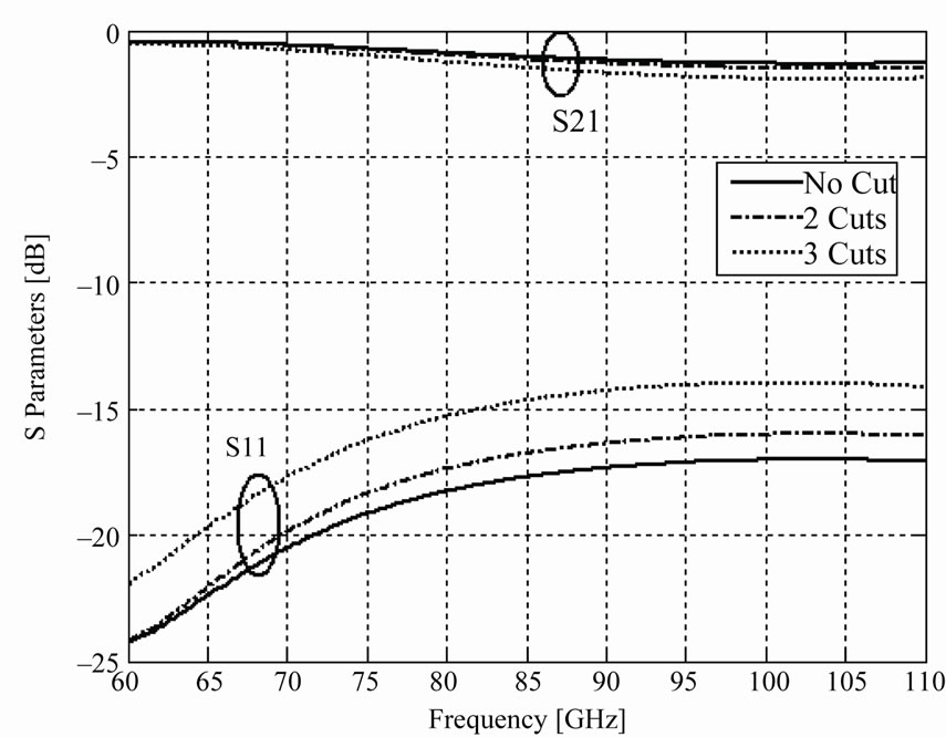
Figure 5. S-parameters of the MEMS switch in upstate with and without cuts.
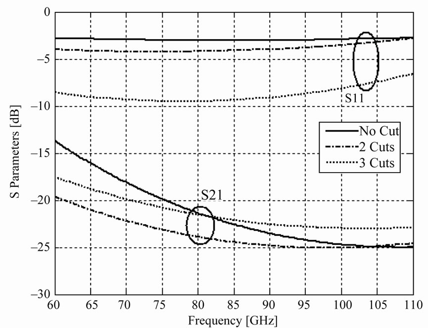
Figure 6. S-parameters of the MEMS switch in down state with and without cuts.
evaluate a RF_MEMS switch performance. The S-parameters of the switch were calculated and compared with measured values in both on and off states which show a good agreement with measurement. It was shown that finite element results are not always reliable especially in case of isolation and return loss. The effect of spring cuts over the bridge were also been analyzed and shown that by increasing the number of these cuts the results were going to show some undesirable behaviors.
5. Acknowledgements
The Authors want to acknowledge the Iran Telecommunication Research Centre for their kindly supports.
REFERENCES
- J. Nutaro, P. T. Kuruganti, R. Jammalamadaka, T. Tinoco and V. Protopopescu, “An Event Driven, Simplified TLM Method for Predicting Path-Loss in Cluttered Environments,” IEEE Transactions on Antennas and Propagation, Vol. 56, No. 1, 2008, pp. 189-198. doi:10.1109/TAP.2007.913083
- J.-M. Gorce, K. Jaffrès-Runser and G. de la Roche, “Deterministic Approach for Fast Simulations of Indoor Radio Wave Propagation,” IEEE Transactions on Antennas and Propagation, Vol. 55, No. 3, 2007, pp. 938-948. doi:10.1109/TAP.2007.891811
- R. A. Sadeghzadeh, A. A. Lotfi Neyestanak, M. Jahanbakht and M. N. Moghaddasi, “Simulation of Wave Propagation through Window Structures by TLM Method,” in Farsi, Iranian Journal of Electrical and Computer Engineering, Vol. 6, No. 1, 2008, pp. 71-76.
- J. A. Portí, J. A. Morente, A. Salinas, E. A. Navarro and M. Rodríguez-Sola, “A Generalized Dynamic Symmetrical Condensed TLM Node for the Modeling of TimeVarying Electromagnetic Media,” IEEE Transactions on Antennas and Propagation, Vol. 54, No. 1, 2006, pp. 2- 11. doi:10.1109/TAP.2005.861543
- H. Jin and R. Vahldieck, “Direct Derivations of TLM Symmetrical Condensed Node and Hybrid Symmetrical Condensed Node from Maxwell’s Equations Using Centered Differencing and Averaging,” IEEE Transactions on Microwave Theory and Techniques, Vol. 42. No. 12, 1994, pp. 2554-2561.
- V. Trenkic, C. Christopoulos and T. M. Benson, “Generally Graded TLM mesh using the Symmetrical Supercondensed Node,” Electronics Letters, Vol. 30, No. 10, 1994, pp. 795-797. doi:10.1049/el:19940552
- Z. Z. Chen and M. M. Ney, “On the Relationship between the Time-Domain and Frequency-Domain TLM Methods,” IEEE Antennas and Wireless Propagation Letters, Vol. 7, 2008, pp. 46-49. doi:10.1109/LAWP.2008.915803
- J. M. Frye and A. Q. Martin, “Extrapolation of Time and Frequency Responses of Resonant Antennas Using Damped Sinusoids and Orthogonal Polynomials,” IEEE Transactions on Antennas and Propagation, Vol. 56, No. 4, 2008, pp. 933-943. doi:10.1109/TAP.2008.919195
- J. Rizk, G.-L. Tan, J. B. Muldavin and G. M. Rebeiz, “High-Isolation W-Band MEMS Switches,” IEEE Microwave and Wireless Components Letters, Vol. 11, No. 1, 2001, pp. 10-12. doi:10.1109/7260.905952
- M. Jahanbakht, M. N. Moghaddasi and A. A. Lotfi Neyestanak, “Fractal Beam Ku-Band Mems Phase Shifter,” Progress in Electromagnetics Research Letters, Vol. 5, 2008, pp. 73-85. doi:10.2528/PIERL08101703
- M. Jahanbakht, M. N. Moghaddasi and A. A. Lotfi Neyestanak, “Low Actuation Voltage Ka-Band Fractal MEMS Switch,” Progress in Electromagnetics Research C, Vol. 5, 2008, pp. 83-92.