Journal of Electromagnetic Analysis and Applications
Vol. 3 No. 8 (2011) , Article ID: 6557 , 8 pages DOI:10.4236/jemaa.2011.38048
A Self-Consistent Model on Cylindrical Monopole Plasma Antenna Excited by Surface Wave Based on the Maxwell-Boltzmann Equation
![]()
1Optics and Electronic Department, Mechanical Engineering College, Shijiazhuang, China; 2College of Information and Communication Engineering, Harbin Engineering University, Harbin, China.
Email: liyingsong@hrbeu.edu.cn
Received June 2nd, 2011; revised July 1st, 2011; accepted July 12th, 2011.
Keywords: Cylindrical Monopole Plasma Antenna, Self-Consistent Mode, Surface Wave, Maxwell-Boltzmann Equation
ABSTRACT
The paper analyzes the motion of electron in plasma antenna and the distribution of electromagnetic field power around the plasma antenna, and proposes a self-consistent model according to the structure of cylindrical monopole plasma antenna excited by surface wave; calculation of the model is based on Maxwell-Boltzmann equation and gas molecular dynamics theory. The calculation results show that this method can reflect the relationships between the external excitation power, gas pressure, discharge current and the characteristic of plasma. It is an accurate method to predicate and calculate the parameters of plasma antenna.
1. Introduction
In the present study of plasma antenna, the plasma antenna is usually simplified as uniform distributed in its density. Borg Harris and Rayner assumed that the electric field and surface current of high-density plasma antenna are distributed in the forms which are similar to those of metal antenna. Signals are transmitted in the form of surface wave propagating along the plasma antenna, and this mode is similar to that of the metal antenna [1-8].
However, there are many limitations in assumptions mentioned above. First, there exists the dual polarity diffusion in the plasma, the radial density of the plasma antenna presents non-uniform distribution, and the resonance absorption also is happened on the border of antenna tube, which changes the space dispersion of the wave and the loss of wave energy. There are no analytical solutions for the electromagnetic field distribution when the density of the plasma presents non-uniform distribution, now, only numerical method can be used in the study. Paper [9] analyzes the electron density distribution in cylindrical monopole plasma antenna, carries out related research when its distribution is non-uniform, and analyzes the influence of electromagnetic field distribution on the plasma antenna parameters, etc.
Igor Alexeff, Ted Anderson, Sriram Parames Waran, and Eric P. Pradeep give a summary of an extensive research program on plasma antennas. They have found that plasma antennas are just as effective as metal antennas. In addition, they can transmit, receive, and reflect lower frequency signals while being transparent to higher frequency signals. When de-energized, they electrically disappear. Plasma noise does not appear to be a problem [10].
Most papers available in literature deal with experimental studies of plasma antennas, and few papers concern theoretical investigation of their behavior and properties [11]. A self-consistent model is necessary to understand and analyze the complex processes involving plasma antenna physics and it is helpful to conduct a parametric investigation of the problem, and to evaluate the optimum parameters in plasma antennas design (frequency and power of pump signal, pressure and gas composition, tube discharge geometry).
Plasma state is affected by input power and frequency of the pump signal applied, and also by the gas pressure and composition and other parameters are involved in the problem. To understand how plasma changes depending on the work conditions adopted is necessary to describe the interaction mechanism between an electromagnetic wave and the plasma. The phenomena can be kinetically modeled through solving a system of equations including the Maxwell curl equations and the Boltzmann equation [12].
In a preliminary study, a simple one dimensional geometry was studied in order to check the accuracy and the self consistency of the model [13]; with some simple assumptions it was possible to derive an analytical solution of the system used to validate the numerical results.
But the self-consistent mode mentioned above is a simple one dimensional, there hasn’t any more accurate model on the surface waved excited plasma antenna system so far. In the paper, we propose a self-consistent model according to the tube discharge geometry of plasma antenna and make the related analysis through the Maxwell-Boltzmann Equation and molecular dynamic theory. All the theoretical aspects concerning electromagnetic wave propagation in plasma are introduced in the model; hence it can be considered as a complete description of [14].
2. Description of Self-Consistent Model
In cylindrical monopole plasma antenna excited by surface wave, as known that small signal is transmitted in the form of surface wave on the antenna surface. The antenna characteristic is mainly determined by the plasma state inside.
As plasma antenna excited by surface wave belongs to weak cold unmagnified plasma, the length of Debye shielding is very short. Therefore, the influence of dispersion can be ignored; the plasma antenna can be modeled according to the electromagnetic field distribution characteristics in radial direction around it. The plasma antenna also can be divided into several parts with uniform distribution in axial direction.
Figure 1 shows the plasma antenna excited by RF power. RF metal coil can be approximately regarded as a series of concentric coils. Electromagnetic energy is coupled into the plasma in the radial direction while it presents uniform distribution in the circular direction.
The inductive electric field presents symmetrical distribution, and the inductive magnetic field presents axial symmetrical distribution around the antenna. When the plasma density is not very high, the inductive magnetic field and the inductive electric field around the plasma antenna present non-uniform distribution. Because the excitation power is usually more than 200 W in the experiment, so the effect of inductive magnetic field can not be ignored.
The existence of the inductive magnetic field makes the motion of electron become very complex, so the calculation of the plasma antenna is very difficult.
In the self-consistent model, the plasma antenna can be
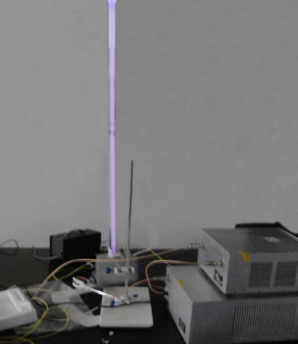
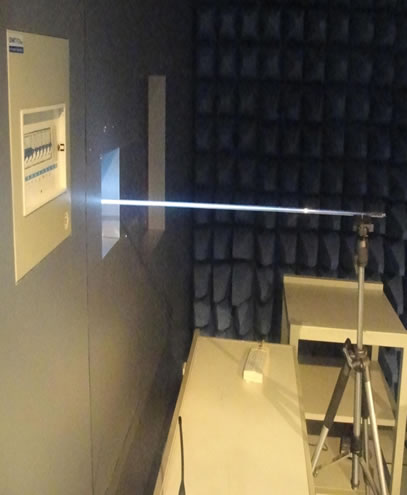
Figure 1. The cylindrical monopole plasma antenna.
divided into many small cylindrical concentric parts. In each cylindrical plane, the plasma density can be regarded as uniform distributed. When the plasma density is high, the permittivity of the plasma in each part can be calculated with the stratification and subsection model according to its distribution along the plasma antenna, just as Figures 2 and 3 showed.
The assumptions of the model are as follows:
1) The plasma antenna is divided into several cylindrical facets at certain lengths in the axial direction and a series of concentric circles according to the distribution characteristic. Hence, the plasma antenna can be regarded as uniform distributed in each part.
2) The frequency of excited RF power far outweighs the frequency of ion oscillation in the plasma.
3) As the plasma density is high, the sheath of the plasma antenna is far shorter than the diameter of the antenna. Therefore, the sheath can be neglected. At the same time, the hot movement of electrons is ignored in the model.
4) In the coordinate system of Figure 2, the electron can be regarded as coming into the plasma from the outer area where ,
,  is the radius of plasma antenna, so calculation area of the equation the can be expanded to
  shown in Figure 2.
5) The time factor of physical parameters is , the Fourier series of inductive electric field can be written as (1).
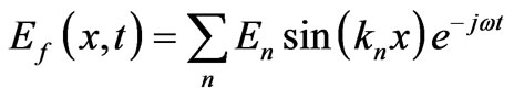 (1)
(1)
where, 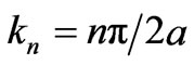 is the number of the wave vector in the Fourier’s space. Through Maxwell Equation
 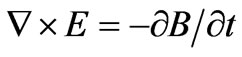 then Equation (2) can be obtained.
 (2)
(2)
where  is the electric field and
  is the in-
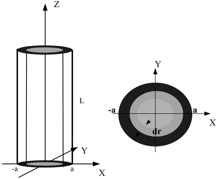
Figure 2. The radial layered structure.
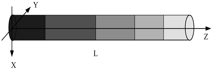
Figure 3. The axial subsection structure.
ductive magnetic filed, the small specific part of plasma antenna presents uniform distribution approximately; the plasma can be analyzed through molecular dynamics and relevant theories.
3. Analysis Based on Molecular Dynamics Theory
In the low temperature plasma antenna, in each part of the plasma antenna divided, the molecular distribution function presents isotropic distribution. The model is based on the distribution characteristics of the electromagnetic field in plasma antenna, the relationships between external electromagnetic filed and the distribution of plasma can be obtained.
The premise of the dynamics theory is that collision frequency of the plasma is far below frequency of electric field, so the collisions of electrons happen in a relative stable electromagnetic field. When the frequency of transmission signal is in the scope of radio frequency, the premise can be satisfied.
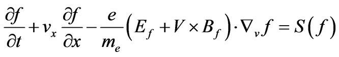
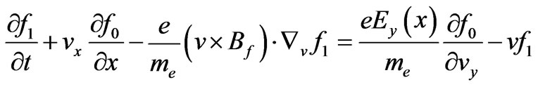
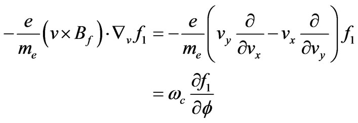
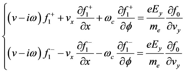
If take the inductive magnetic field into consideration, and make hypothesis that electron distribution function satisfies the Boltzmann Equation (3).
 (3)
(3)
Because the plasma is discharged in low pressure and high-frequency power condition, the hypothesis is as (4),
 (4)
(4)
where  denotes the quality of the electron, e denotes the elementary charge,
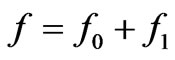
  represents the distribution function caused by collisions, f0 is the balance distribution and f1 is the disturbance distribution, and
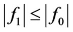 . From the Equations (3) and (4), the following Equations (5) and (6) can be obtained.
 (5)
(5)
 (6)
(6)
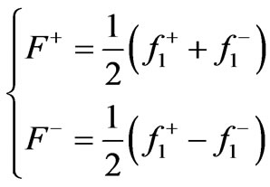
where ,
,  ,
,  separately represents the velocity of electron in the direction of x, y, z. If
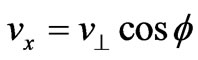 ,
, 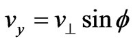 ,
, 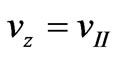 ,
,  and
and  represent the parallel part and vertical part of the velocity part which are separately parallel and vertical to the direction of magnetic field, the direction angel in speed space is
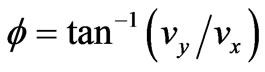 , so the Equation (7) is obtained.
 (7)
(7)
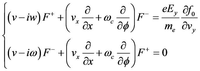
where 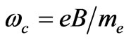 is electron cyclotron rate. If
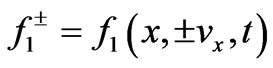 ,
,  , the Equation (2) can be written as Equation (8).
 (8)
(8)
If
 (9)
(9)
the (8) can be rewritten as (10)
 (10)
(10)
If the “mirror reflect” of electrons are happened on the boundary of the plasma antenna, the (11) can be obtained,
 (11)
(11)
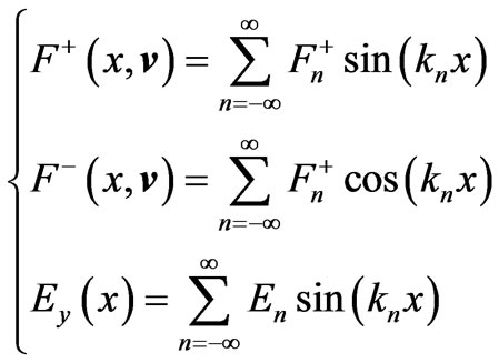
The disturbance distribution function can be expressed as (12),
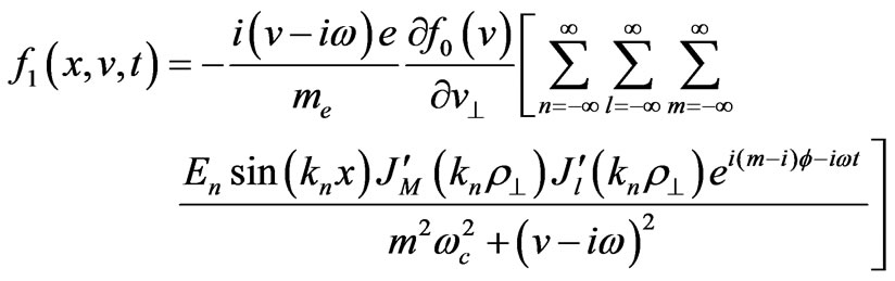 (12)
(12)
where  is electron cyclotron radius,
  is the first kind Bessel function;
  is symbol of
  and
and ,
, are the integer.
When disturbance distribution function is obtained, then the following differential Equation (13) can be obtained.
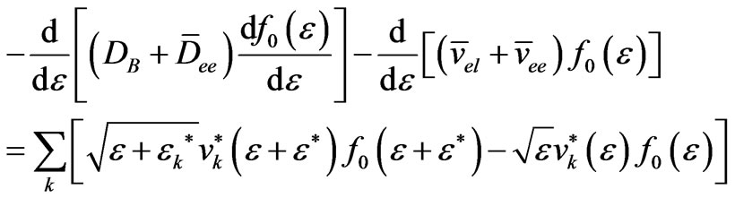 (13)
(13)
where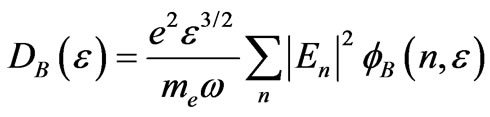 ,
,
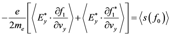
So the conductivity of the plasma in the Fourier space can be expressed as (14).
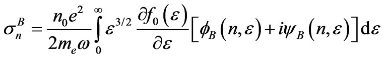 (14)
(14)
The interaction function of electromagnetic field is as (15).
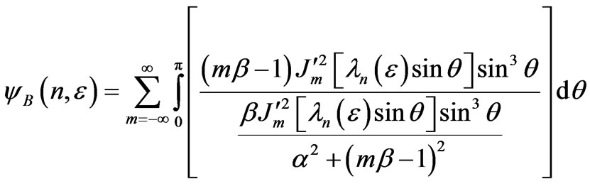 (15)
(15)
In the each divided part, the distribution of plasma presents approximately uniform, with the change of external excitation electromagnetic field, the current and conductivity can be written as (16) and (17).
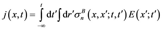 (16)
(16)
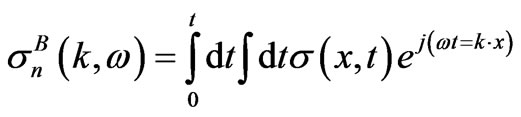 (17)
(17)
A series of equations of self-consistent model are deduced above, from which the physics parameters of plasma antenna can be obtained, such as conductivity, dielectric tensor, surface current and electromagnetic field distribution, etc.
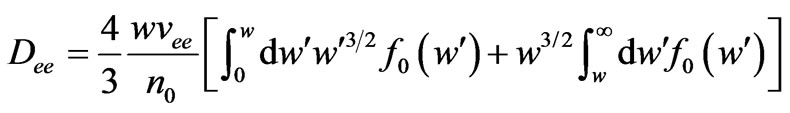
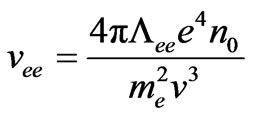
4. Numerical Calculation Method
If the length of plasma, frequency of transmission signal, antenna radius, the amplitude of antenna surface current, and the plasma density in each divided part of the plasma antenna are known. The calculation process is as follows.
Plasma density is n0 and pressure is p, the electron energy distribution function is  are the initial condition, the first step is to solve electromagnetic equations to obtain the value of En, and get the energy diffusion coefficient DE. Through solving the dynamic equation, get the new distribution functions
 . The second step is to judge whether the
  is convergence. If not, the calculation will be continued, until a stable result is obtained. The last step is to derive
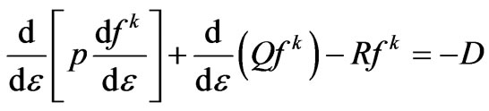
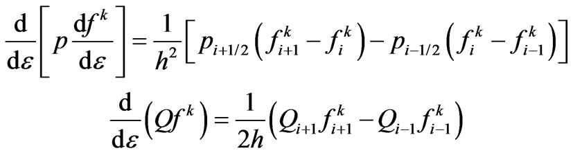
 , and gets the spatial distribution of electromagnetic field in small part. When the plasma density, frequency of plasma collision, radius of the plasma antenna are known, the finite difference method can be adopted as (13), which can be simplified as (18),the calculation process is as Figure 4 shows,
 (18)
(18)
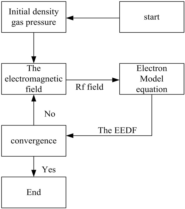
Figure 4. Flow diagram used for numerical calculation.
where ,
, ,
,
 , k is the times of iteration, the energy
  is divided into
  parts and the interval is h.
So, on the grid points of energy , it can be expressed as (19)
 (19)
(19)
Then its abbreviations and differential form can be expressed as Equation (20),
 ,
,  ,
,  ,
,  ,
, 
 (20)
(20)
The number of linear equations is .
.
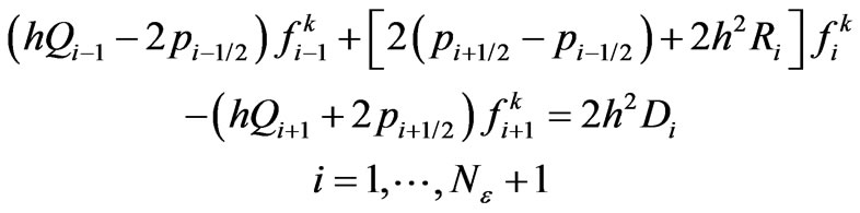 (21)
(21)
Equation (21) is a coefficient diagonal matrix, which can be solved though diagonal matrix and the process are iterative until the convergence result is obtained, and then iterative calculation process is over. In the iterative calculation process, the normalization conditions of Equation (22) must be satisfied with.
 (22)
(22)
After the expression of f0 is obtained, the distribution of electromagnetic field around the plasma antenna can be worked out.
5. Analysis and Discussion
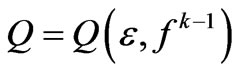
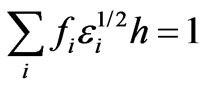
When the gas pressure is p, the discharge current is I, ω is the frequency of the excitation field, R is the radius of the plasma antenna, L is the length of the plasma column, the relationship between EEDF (electron energy distribution function) and the discharge current, the gas pressure of the plasma antenna are shown as Figures 5 and 6.
From Figures 5 and 6 it can be found that the EEDF present the non-Maxwell distribution, in the low gas pressure the collisions between the electron and the neutral particle are reduced, so more electrons in the plasma can keep high energy state. It can also be shown that with the increasing of discharge current or the reducing of the pressure in the plasma antenna, the number of the high energy electrons are increased in the plasma antenna.
The strength of current in the RF coil reflects the external excitation power directly, and it determines the power that coupled into plasma antenna. As shown in Figures 7 and 8, the EEDF changes with the strength of current in the coil. When discharge current and the number of coil are
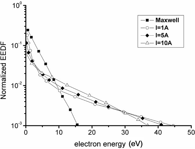
Figure 5. The normalized EEDF as function of the electron energy for different RF currents and different pressures.
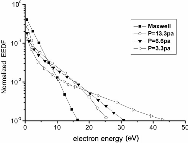
Figure 6. The normalized EEDF as function of the electron energy for different RF currents and different pressures.
Figure 7. Influence of RF current amplitude of the plasma antenna on the EEDF, other parameters are ω = 2π × 13.56 MHz, p = 15 Pa, R = 1 cm, L = 10 cm.
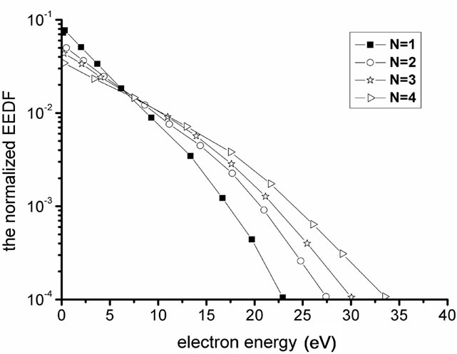
Figure 8. Influence of turns number of the plasma antenna on the EEDF, other parameters are, ω = 2π × 13.56 MHz, p = 15 Pa, R = 1 cm, L = 10 cm.
increased, the electron energy also is increased. Because the excitation power is increased, the absorption power of plasma is also increased. So the state of the plasma can be controlled through changing the number of coils and RF discharge currents in the coupling coil.
It can be seen that self-consistent model can be used in the control and predication of the plasma antenna.
The distribution of the RF electric field in the selfconsistent model and Maxwell distribution along the antenna axial direction is shown in Figures 9 and 10. It can be seen that results of Maxwell distribution show index attenuation distribution in the electric field, with the increase of the current, the electric field only increases correspondingly in its intensity, and the characteristic of the Maxwell distribution of the electric field is not changed. While the calculation results of self-consistent model show a strong abnormal behavior, electric field is attenuated to a tiny value rapidly, and then is increased to a maximum value slowly and then is attenuated again, especially with the increasing of the current, the abnormal behavior is increasingly obviously. This is because in low pressure, the average free distance of electron is
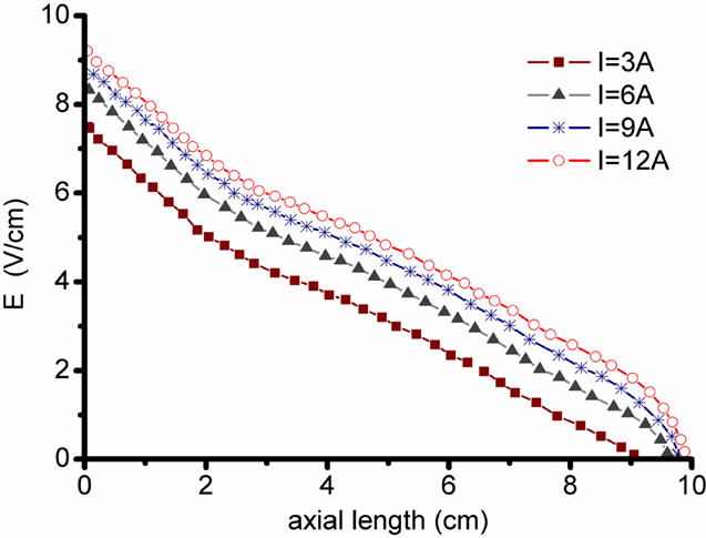
Figure 9. The distribution of RF eclectic field calculated from Maxwell distribution.
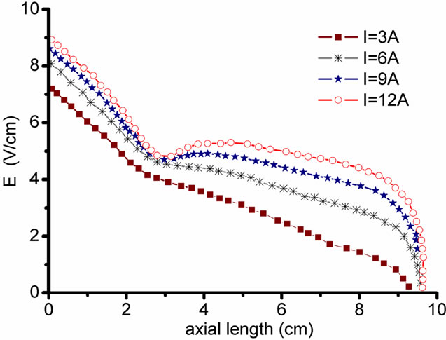
Figure 10. The distribution of RF eclectic field calculated from the self-consistent model.
bigger than the scale of the ion movement, the electron heating in plasma is a king of heat without collision. When the speed of electron is approaching to the velocity of wave, the Landau damping will be happened which leads to the abnormal behavior of the electric field.
Figure 11 is the distribution of the electric field of the experimental results, the Figure 12 is the calculation results of the self-consistent model, it can be found that the experimental results and the results of the self-consistent model show the same trend of changing, and there only exists some errors, if we improve the calculation method of the self-consistent mode, the more precise results will be obtained. Through the related experimental measuring the validity of the model proposed is verified.
Now the common calculation method of the plasma antenna is to use one of the many variations of the numerical electromagnetic code (NEC) method of Moments computer packages. Several are available from http:// www.qsl.net/wb6tpu/swindex.html. NEC is widely used for modeling antennas and their environment. The antenna structure is broken down into short wires and small surface areas, from which the current distribution and the radiation pattern may be found. Using a computer program,
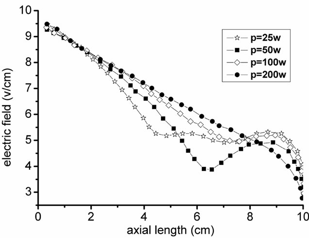
Figure 11. Electric field distribution of the experiment.
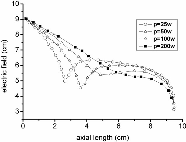
Figure 12. Electric field distribution of self-consistent model.
it may readily change the conductivity of the small current elements that comprise the antenna structure [8].
Compared with the method in the [8], the self-consistent model can reflect the relationship between the excitation field and the inner particle state of the plasma antenna, so it is a more precise method, as known that the plasma is a time-changing medium, the method in the [8] only reflect the characteristic of the plasma antenna in certain condition.
6. Conclusions
The calculation of plasma antenna is a very complicated problem, especially when the electric field around the plasma antenna presents non-uniform distribution. The simulation based on FDTD software cannot reflect the effect of particle motion inside the antenna and the external excitation power to the plasma. So the method based on software has many limitations and with low precision. But through self-consistent model method proposed in the paper, and make calculation analysis of particle motion in plasma antenna, more precise results can be obtained. The self-consistent model can be used in the quantitative analysis and state prediction of the plasma antenna, and it is the guidance to the plasma antenna research.
7. Acknowledgements
This Project is supported by the National Science Research Foundation of China (Grant No. 9140A25030210 JB30).
REFERENCES
- B. A. Anicin, “Plasma Loaded Helicon Waveguide,” Journal of Physics D: Applied Physics, Vol. 33, 2000, pp. 1276-1281. doi:10.1088/0022-3727/33/11/305
- I. D. Sudit and F. F. Chen, “A Non-Singular Helicon Wave Equation for a Non-Uniform Plasma,” Plasma Sources Science and Technology, Vol. 3, No. 4, 1994, pp. 602-603. doi:10.1088/0963-0252/3/4/018
- B. Davies and P. J. Christiansen, “Helicon Waves in a Gaseous Plasma,” Plasma Physics, Vol. 11, No. 12, 1969, pp. 987-1000. doi:10.1088/0032-1028/11/12/004
- F. F. Chen, “Plasma Ionization by Helicon Waves,” Plasma Physics and Controlled Fusion, Vol. 33, No. 4, 1991, pp. 339-364. doi:10.1088/0741-3335/33/4/006
- D. G. Miljak and F. F. Chen, “Helicon Wave Excitation with Rotating Antenna Fields,” Plasma Sources Science and Technology, Vol. 7, No. 1, 1998, pp. 61-74. doi:10.1088/0963-0252/7/1/009
- G. G. Borg and J. H. Harris, “Plasmas as Antennas Theory, Experiment and Applications,” Physics of Plasmas, Vol. 7, No. 5, 2000, pp. 2198-2202. doi:10.1063/1.874041
- G. G. Borg and J. H. Harris, “Application of Plasma Columns to Radio Frequency Antennas,” Applied Physics Letters, Vol. 74, No. 22, 1999, pp. 3272-3275. doi:10.1063/1.123317
- J. P. Rayner and A. P. Whichello, “Physical Characteristics of Plasma Antennas,” IEEE Transactions on Plasma Science, Vol. 32, No. 1, 2004, pp. 269-281. doi:10.1109/TPS.2004.826019
- H. Nowakowska, Z. Zakrzewski and M. Moisan, “Propagation Characteristics of Electromagnetic Waves along a Dense Plasma Filament,” Journal of Physics D: Applied Physics, Vol. 34, No. 10, 2001, pp. 1474-1478. doi:10.1088/0022-3727/34/10/307
- I. Alexeff and T. Anderson, “Experimental and Theoretical Results with Plasma Antennas,” IEEE Transactions on Plasma Science, Vol. 34, No. 2, 2006, pp.166-178. doi:10.1109/TPS.2006.872180
- M. Moisan and Z. J. Zakrzewski, “Plasma Sources Based on the Propagation of Electromagnetic Surface Waves,” Journal of Physics D: Applied Physics, Vol. 24, No. 7, 1991, pp. 1025-2048. doi:10.1088/0022-3727/24/7/001
- A. P. Žilinskij, I. E. Sacharov and V. E. Golant, “Fundamentals Plasma Physics,” MIR, Moscow, 1983.
- G. Cerri, F. Moglie, R. Montesi, P. Russo and E. Vecchioni, “FDTD Solution of the Maxwell-Boltzmann System for Electromagnetic Wave Propagation in a Plasma,” IEEE Transactions on Antennas and Propagation, Vol. 56, No. 8, 2008, pp. 2584-2588. doi:10.1109/TAP.2008.927505
- G. Cerri, P. Russo and E. Vecchioni, “A Model of Gas Ionisation by an Electromagnetic Field to Be Used for Plasma Antennas Characterization,” IEEE Transactions on Plasma Science.