Journal of Electromagnetic Analysis and Applications
Vol. 2 No. 1 (2010) , Article ID: 1221 , 6 pages DOI:10.4236/jemaa.2010.21001
Coupling of the Magnetostriction and Hall Effect in the Porous Magnetorheological Composite
![]()
Department of Physics and Applied Informatics, University of Lodz, Lodz, Poland.
Email: bedastan@uni.lodz.pl
Received August 4th, 2009; revised September 13th, 2009; accepted September 20th, 2009
Keywords: Hall Effect, Magnetostriction, Non-linearity, Hysteresis, Composite, Porous, Elastic, Ferromagnetic
ABSTRACT
The first part of this paper is presents a method for producing the composite which shows ferromagnetic, highly-elastic and electrically-conducting properties. This composite consists of ferromagnetic particles of the size 0.15-0.25 mm made of the chemically pure iron. The mentioned particles were dispersed in the elastic porous silicone the matrix with pores of the size 0.15-0.25 mm. Colloidal graphite particles of the size not exceeding 0.5 µm were added to the matrix to increase electrical conductivity. The production method consist in mixing particles of iron, graphite and sodium chloride with non-polymerized silicone and rinsing salt particles by water after the matrix polymerization. In its second part the paper provides a description of the measurement system for longitudinal magnetostriction and the Hall voltage. The magnetic field with the induction of ± 8 T produced by the Bitter type magnet was applied to the composite samples. The supplying voltage was applied to these samples and the Hall voltage was measured at the electrodes glued to them. The longitudinal magnetostriction was measured by means of the capacitor with a variable capacity placed at the upper surface of these samples. The linear magnetostriction exceeding ± 6 % and the Hall voltage reaching ± 5.5 nV were detected by the conducted measurements. Both the longitudinal magnetostriction and the Hall voltage show nonlinear changes and hysteresis lopes during the magnetic field application and the supplying current flow. The coupling of these changes and other regularities observed in the investigated composites and especially their non-linearity and hysteresis, are discussed in the final part of the paper.
1. Introduction
The mechanism of magnetostriction involves the changes in the dimension of the magnetized body as a result of its magnetization when placed in the external magnetic field [1,2]. The Hall effect refers to the potential difference on the opposite sides of an electrical conductor through which an electric current is flowing, created by a magnetic field with induction perpendicular to the current flow [3,4]. In normal conductors each of these phenomena appears to occur independently and thus is discussed independently. The paper aims to present both the measurement results of the longitudinal magnetostriction and the Hall voltage. These measurements have been obtained using the samples of elastic porous ferromagnetic composite.
2. The Preparation of Samples
For the measurements, the samples in a cuboid shape, size: 35 mm long, 21 mm wide, and 21 mm high, were used. The sample dimensions in horizontal cross-section were restricted by the Bitter magnet aperture. The magnet with the 43 mm aperture was used to create a magnetic field. The width-to-length ratio of 5:3 of a sample measuring approximately 35 by 21 mm, was assumed. The structure of the samples produced is presented in the cross-section in Figure 1 [5]. Prior to the sample production, the composites containing ferromagnetic particles of chemically pure iron, size 0.15-0.25 mm, as well as the particles of colloidal graphite of the size not exceeding 0.5 µm, were produced first. The pores in the samples were produced through resolving and rinsing sodium chloride grains of the size 0.15-0.25 mm. The particles of iron and sodium chloride of desirable sizes were obtained as a result of grinding and sieving.
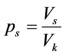
In order to produce the composites, chemically pure particles of iron, sodium chloride particles and colloidal graphite particles were measured in appropriate proportions. The quantity of the particles used for the mixture was determined by the filling factor ps [6,7]. The filling factor is defined as the ratio of the volume of a given
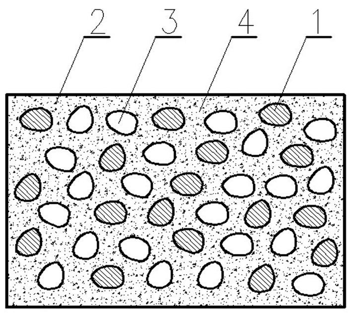
Figure 1. Structure of the elastic, porous, ferromagnetic composite presented in cross section: 1—particle of chemically pure iron with dimensions 0.15-0.20 mm, 2—particle ofcolloidal graphite with dimensions not exceeding 0.5μm, 3— pore with dimensions 0.15-0.20mm, 4—silicone matrix
component Vs to the total composite volume Vk, which can be expressed by the general formula:
 (1)
(1)
The volumes of particles were mixed together for 15 min.
A bonding substance was added to the mixture which constituted the composite matrix. The substance contained non-polymerized silicone available commercially as the adhesive/sealing mass. The silicone has a gel consistency and is sold in hermetically sealed tubes as it contains polymerization initiator which is easily activated by atmospheric air. The particles were mixed with a measured quantity of silicone for 20 min. The mixture obtained in the process was formed into cuboid shape at the above mentioned sizes.
The cuboids which were obtained from the mixture were left to remain at the temperature of 20 ºC for 48 hours, during which time a complete polymerization of silicone occurred. Subsequently, pores were produced through resolving and rinsing sodium chloride. To obtain this effect, the cuboid was submitted to the water flux and was periodically kneaded with hands. The successive resolution and rinsing of sodium chloride were conducted for 3 hours. Following the process of pore formation the samples obtained in the process were dried up in the flux of hot air produced by the supercharger at the temperature of 35 ºC.
3. The Measurement System
The way of establishing connections between the composite sample and the measurement process is outlined in Figure 2. In the centers of the two opposing walls which make squares at 21 mm at one side, the ends of wires a-a
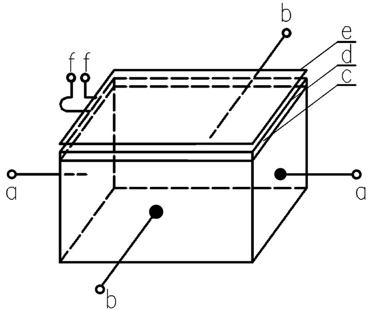
Figure 2. Preparation of the connections of sample to measurements: a-a—ends of the supply Voltage wires, b-b—ends of wires for the Hall voltage measurement, c—pad made ofTeflon, d—movable capacitor plate, e—immovable capacitor plate, f-f—ends of capacitor plates
were glued as a means for supplying voltage. Impacted by the voltage activity, an electric current flowed through the sample causing the Hall effect. To glue the ends, graphite glue composed of colloidal graphite and non-polymerized silicone was applied for better contact and conductivity, with a volume filling factor for graphite of 0.6.
Then, in the centers of the two opposite sides making rectangles of 35 by 21 mm at the sides, the ends of wires b-b were glued for measuring the Hall voltage. The same graphite glue was applied to attach the ends. At the top of the sample, the pad c made of 1 mm thick Teflon, was applied to the sample with a pure non-polymerized silicone. An electrode d in the form of a rectangular strip of copper foil was also glued with pure silicone.
The electrode consisted of a movable plate of the condenser with a variable capacity, which was employed to measure magnetostriction [8]. Non-movable plate e of the condenser was a rectangular strip of copper foil of the identical size as the movable plate. Into the edge of each of the plates, the ends of wires f-f were soldered to connect them to the capacity meter. The end of wire connected to the movable pad was made of a flexible material such as lice and supplied with a loop. Such a solution allowed for an easy adjustment of the necessary distance between the capacitor plates.
The setup applied for the simultaneous measurements of the Hall voltage and longitudinal magnetostriction is presented in Figure 3. A sample of elastic porous ferromagnetic composite 1 of the dimensions provided above was placed on a horizontal insulation base plate 2 of textolite. The base plate was fastened into two vertical brass rods 3 and inserted into the aperture of the Bitter magnet coil 4. The ends of wires for the voltage supply a-a as
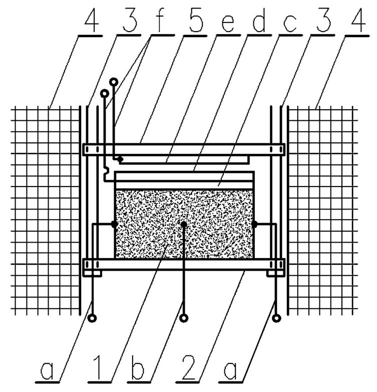
Figure 3. Construction of the measurement system: 1—sample of elastic, porous, ferromagnetic composite, 2—basis, 3— brass rood, 4—winding of Bitter magnet coil, 5—insulating plate; the remaining letters have the same significance as in caption under Figure 2
well as the ends for measuring the Hall voltage b-b were glued into the sample. The sample was fixed with a pad c of Teflon and a movable condenser plate d. Above the sample on the rods 3 an isolation plate 5 cut out from an electrical insulating material—textolite was placed, to which immovable capacitor plate e was attached. The ends f-f were soldered into each of the capacitor plates connecting them into the bridge specially designed for measuring capacitance. The sensitivity of the bridge amounted to 0.01 pF.
The Bitter magnet at the International Laboratory of the High Magnetic Field and Low Temperatures in Wroclaw was employed to generate the magnetic field in which the sample was placed. The magnet could practically create the magnetic fields with the maximum induction 8 T, with an option to invert their direction. The supply voltage of 3000 V came from the constant current generator. To disperse the Joule heat produced by the current flow, the magnet coil was cooled with water flowing along axial direction.
4. The Discussion of Results
While using the setup described above, the measurements of the Hall voltage UH and longitudinal magnetostriction—measured by the relative elongation Δl/l0 on dependence of the magnetic induction of B the applied magnetic field—were conducted. The magnetic field induction was changed from 0 T to + 8 T and to – 8 T, and eventually to 0 T. The measurements were carried out for the samples with varied filling factors for ferromagnetic particles of chemically pure iron pf, and for colloidal graphite particles pg, with the filling factor for ferromagnetic particles amounting to 0.3, 0.2 or 0.1 and correspondingly for graphite particles to 0.2 or 0.3. However, the porosity factor pp amounted to 0.2 and remained constant for all the samples. In sum, five samples were investigated. The results of the Hall voltage dependencies UH and longitudinal magnetostriction Δl/l0 on the value of the magnetic induction B are presented in Figure 4-8. To obtain the curves as presented in the figures, the least square method was applied [9].
When analyzing the charts it is easy to observe that the dependences of both the Hall voltage UH and longitudinal magnetostriction Δl/l0 on the value of the magnetic field induction B have a non-linear character. A review of the hitherto known cases of the occurrence of the Hall effect in conductors and semiconductors, the Hall voltage revealed a linear dependence on the value of the magnetic field induction B [7]. The evidence of non-linearity ascertained in our investigation can be regarded as something of a novelty. Together with the increase in the magnetic field induction B, there is an increase in the Hall voltage UH and longitudinal magnetostriction [10,11]. The extreme Hall voltage amounting to 5.5 nV in the magnetic field with the induction of 8 T was found in the sample with the following filling factors: pf = 0.3, pg = 0.2, pp = 0.2 and in the sample with the filling factors: pf = 0.2,
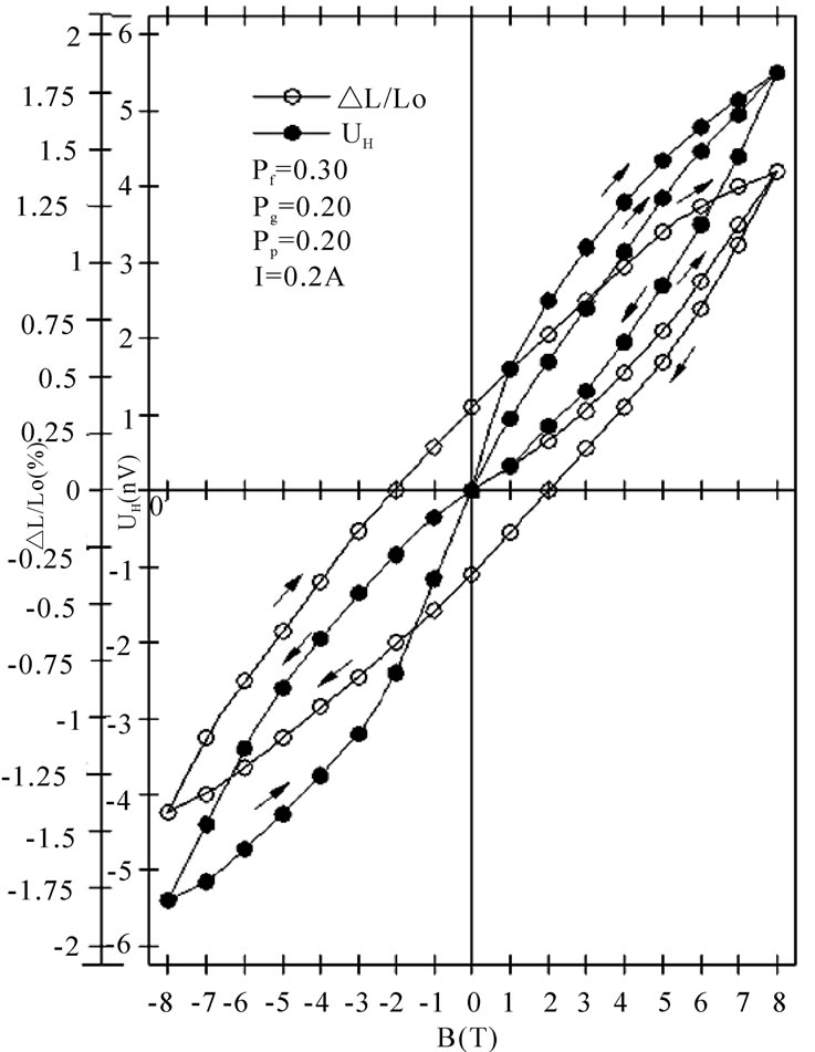
Figure 4. Dependences of longitudinal magnetostriction Δl/l0 and the Hall voltage UH on the magnetic induction B for sample with filling factor for with ferromagnetic particles pf = 0.3, filling factor for graphite particles pg = 0.2, porosity factor pp = 0.2. The intensity of supply current I = 0.2 A
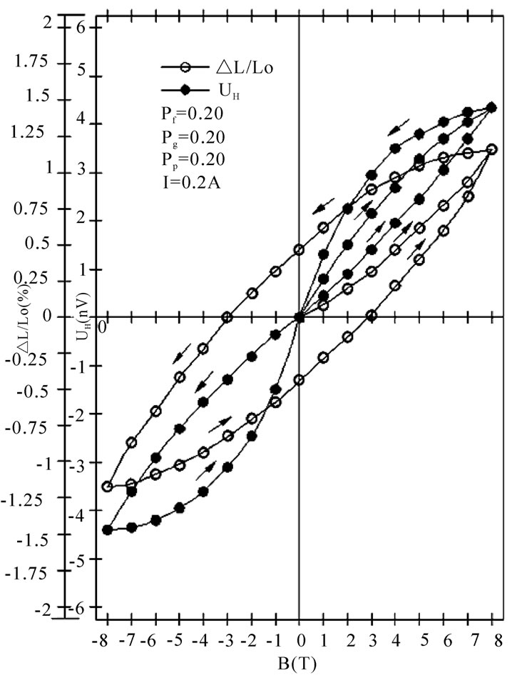
Figure 5. Dependences of longitudinal magnetostriction Δl/l0 and the Hall voltage UH on the magnetic induction B for sample with filling factor for ferromagnetic particles pf = 0.2, filling factor for graphite particles pg = 0.2, porosity factor pp = 0.2. The intensity of supply current I = 0.2 A
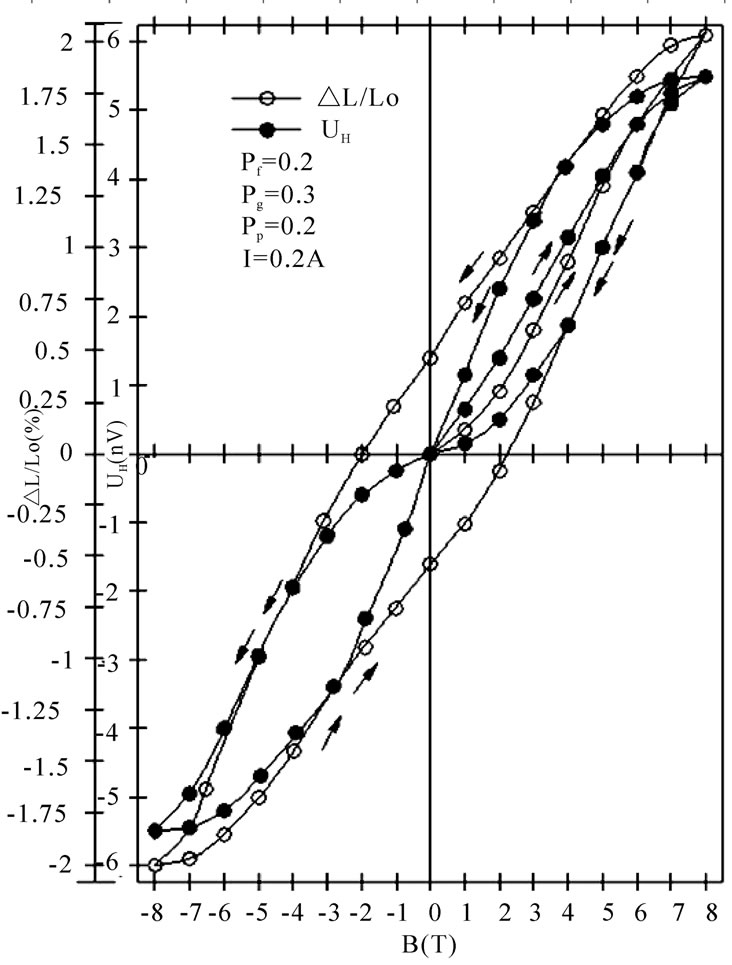
Figure 7. Dependences of longitudinal magnetostriction Δl/l0 and the Hall voltage UH on the magnetic induction B for sample with filling factor for ferromagnetic particles pf = 0.2, filling factor with graphite particles pg = 0.3, porosity factor pp = 0.2. The intensity of supply current I = 0.2 A
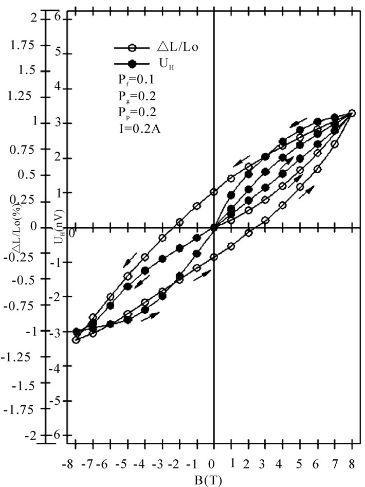
Figure 6. Dependences of longitudinal magnetostriction Δl/l0 and the Hall voltage UH on themagnetic induction B for sample with filling factor for ferromagnetic particles pf = 0.1, filling factor for graphite particles pg = 0.2, porosity factor pp = 0.2. Theintensity of supply current I = 0.2 A
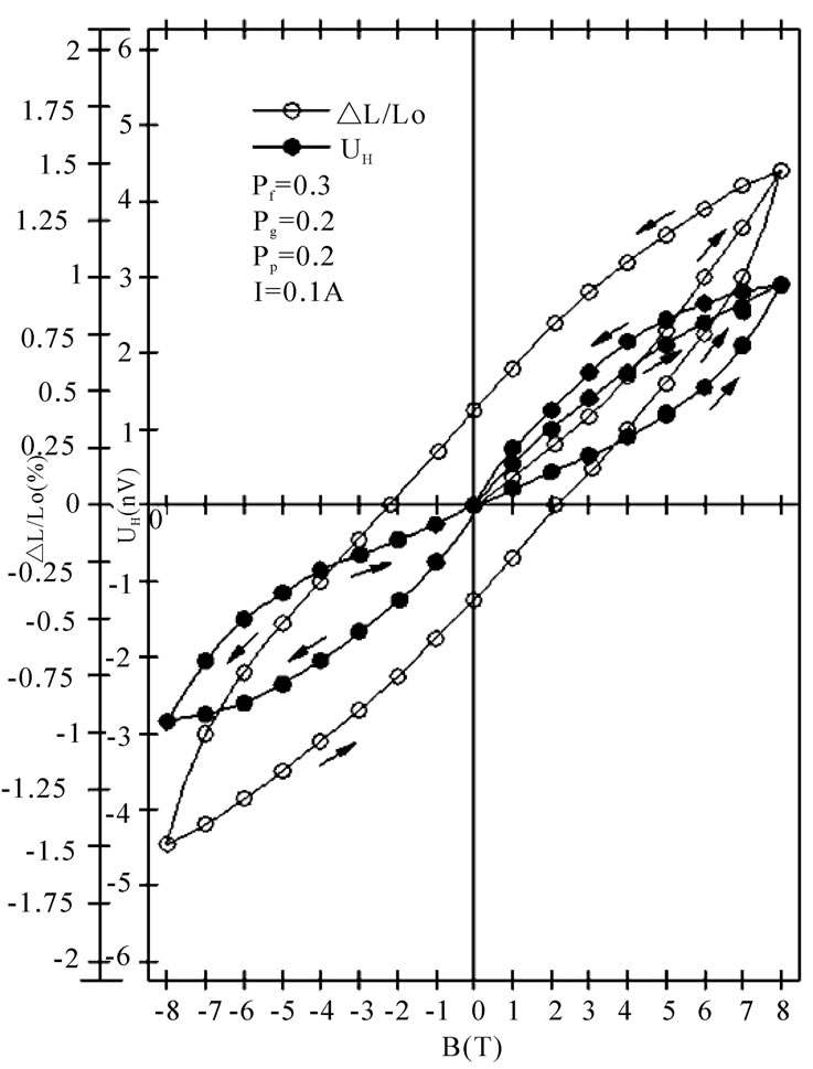
Figure 8. Dependences of longitudinal magnetostriction Δl/l0 and the Hall voltage UH on the magnetic induction B for sample with filling factor for ferromagnetic particles pf = 0.3, filling factor with graphite particles pg = 0.2, porosity factor pp = 0.2. The intensity of supply current I = 0.1 A
pg = 0.3, pp = 0.2.
The extreme value of longitudinal magnetostriction Δl/l0 amounting to 6.1% was found in the sample with the filling factors pf = 0.2, pg = 0.3, pp = 0.2 with the magnetic field induction 8 T. The ascertained value of magnetostriction may be compared with a gigantic magnetostriction which is found in the alloys of rare earth elements such as dysprosium and terbium [1,2]. Yet, there is a real difference between these materials. The dysprosium and terbium alloys have a significantly more measures of the Young’s modulus than the samples of the composite under investigation. For that reason, the potential energy of elasticity which has been accumulated in the deformed sample is far smaller than the energy of elasticity in the alloys of rare earth elements or nanocomposite materials [12,13]. The difference may prove to be important in the case of application of the investigated composite, e.g. in the construction of electromechanical transductions and sensors.
The dominant cause of a giant magnetostriction in the investigated composite is the deformation of porous silicone matrix after it has been placed in the magnetic field. In a model way, it was presented in Figure 9. Ferromagnetic particles undergo magnetization and tend to pitch in such a way that the directions of their easy magnetization follow the magnetic field lines. As a result of this, the magnetized particles act at the matrix causing its elongation. The porosity of the matrix is the factor which helps its elongation, as the fine walls of the matrix are apt to yield to bending and tension easier [14]. Some contribution to the sample magnetostriction is also made by the
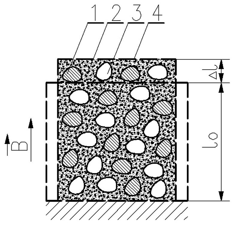
Figure 9. Structure of elastic, ferromagnetic porous composite after elongation presented in cross section: l0—initial length, Δl—elongation, B—value of the magnetic field induction decisive significance for creation of magnetostriction in investigated composites the remaining symbols have the same significance as in caption under Figure 1
magnetostriction of the particles and the matrix themselves. Yet, this contribution is insignificant.
The maximal values of the Hall voltage UH and longitudinal magnetostriction Δl/l0 depend on the composition of the composite sample. When analyzing Figure 4-6, it is evident that a decrease in the content of the chemically pure iron particles, measured by coefficient pf from 0.3 to 0.1 has caused a reduction of the maximal value of the Hall voltage from 5.5 nV to 3 nV and reduction of the maximal value of magnetostriction from 1.27 % to 1.03 %. In turn, an increase in the content of graphite particles measured by the increasing factor pf from 0.2 to 0.3 caused an increase in the maximal Hall voltage from 3 nV to 5.5 nV (see Figure 6 and 7).
The increasing maximal value of magnetostriction with the increase in ferromagnetic particles content can be explained by the fact that the samples with greater ferromagnetic particles content interact with the magnetic field more strongly. These samples undergo greater deformation in the same magnetic field, which signifies greater magnetostriction. Subsequently, an increase in the maximal Hall voltage value together with the growth of both ferromagnetic particles content and graphite particles content can be easily explained by the increase in the electrical conductivity of the samples [14].
Both the Hall voltage UH and longitudinal magnetostriction Δl/l0 show hysteresis, manifested in the decelerations of changes of their quantities in ratio to changes of the magnetic field induction. The hysteresis loop of magnetostriction shows a form which resembles an ellipse, however hysteresis loop of the Hall voltage has a form of an inclined number eight.
5. Conclusions
The conducted investigations of the porous magnetorheological composite enable to formulate the following conclusions:
1) The measured longitudinal magnetostriction Δl/l0 and the Hall voltage UH show a non-linear dependence on the induction of the applied magnetic field B. This non-linearity is characteristic of inhomogeneous media such as composites and mixtures, for example [15,16].
2) The maximal achieved values of the longitudinal magnetostriction Δl/l0 and the Hall voltage UH are dependent on the filling factor of the composite by ferromagnetic particles, graphite particles and its porosity factor. Influences of these factors are competitive.
3) Both the longitudinal magnetostriction Δl/l0 and the Hall voltage UH show hysteresis lopes. The main difference between these lopes lies in the zero value of the Hall voltage UH for the zero value induction of the magnetic field B and the non-zero value of the longitudinal magnetostriction Δl/l0 for this B value. One possible case of this hysteresis appears to be the interaction at interfaces between particles and the matrix and the interruption of their connection [14,17].
4) The magnetic interaction of iron particles with the magnetic field and the elastic susceptibility of silicone matrix are of decisive significance for creation of the magnetostriction in the investigated composites [18].
5) The detected values of the longitudinal magnetostriction Δl/l0 in the investigated composite are comparable with values of the giant magnetostriction in the alloys of rare earth elements and nanocomposite materials [12,13], but this composite shows a significantly smaller Young modulus and accumulation of a smaller elastic energy during deformation.
6. Acknowledgements
The investigations described in this article were carried out in the International Laboratory of High Magnetic Fields and Low Temperatures in Wroclaw. The author would like to express his gratitude to Professor Tomasz Palewski, the Director of this Laboratory for Research, for giving me a possibility of using the Bitter’s magnet in this Laboratory in these investigations.
REFERENCES
- J. B. Restoroff, “Magnetosrtictive materials and devices,” In G. L. Trigg, Edition, Encyclopedia of Applied Physics, VCH Publisher Inc., Berlin, New York, Tokyo, Vol. 9, pp. 229–244, 1994.
- M. R. Ibarra Garcia, “Magnetoelasticity,” In F. Bassani, G. L. Liedl, P. Wyder, Edition, Encyclopedia of Condensed Matter Physics, Elsevier-Academic Press, Amsterdam, Vol. 3, pp. 245–248, 2005.
- O. P. Hansen, “Electronic transport in solids,” In G. L. Trigg, Edition, Encyclopedia of Applied Physics. VCH Publisher Inc., Berlin, New York, Tokyo, Vol. 6, pp. 121–136, 1993.
- J. Bass, “Conductivity: Electrical,” In F. Bassani, G. L. Liedl, P. Wyder, Edition, Encyclopedia of Condensed Matter Physics., Elsevier-Academic Press, Amsterdam, Vol. 1, pp. 219–234, 2005.
- S. Bednarek, “Composite magnetic materials and production method of thereof,” PL. Patent 184,856, January 23rd, 2003.
- L. M. Malkinski, “A comparison between two magnetomechanical methods,” Journal of Magnetism and Magnetic Materials, Vol. 140–144, pp. 2169-2170, 1995.
- H. Ibach and H. Lüth, “Solid-state physics: An introduction to principles of materials science,” Springer-Verlag, Berlin, Heidelberg, 1995.
- F. Kohlrausch, “Praktische physik, Verraten über Herman Ebert und Edward Justi,” Band II, Verlagesellschaft, Stuttgart, 1956.
- G. L. Squires, “Practical physics,” Cambridge University Press, Cambridge, 1985.
- J. M. Gindr, “Rheology controled by magnetic fields,” In Trigg, G. L. Edition, Encyclopedia of Applied Physics, VCH Publisher Inc., Berlin, New York, Tokyo, Vol. 16, p. 487–503, 1996.
- M. Le Floc’h, J. L. Mettei, P. Laurent, O. Minot, and A. M. Konn, “A physical model for heterogeneous magnetic materials,” Journal of Magnetism and Magnetic Materials, Vol. 140–144, pp. 2191–2192, 1995.
- R. Fischer, T. Sherfl, H. Kronmüller, and J. Fiedler, “Phase distribution and computed magnetic properties of high-remanent composite magnets,” Journal of Magnetism and Magnetic Materials, Vol. 150, pp. 329–338, 1995.
- M. Jurczyk and J. Jakubowicz, “Nanocomposite Nd2 (Fe, Co, Cr)14B/α-Fe materials,” Journal of Magnetism and Magnetic Materials, Vol. 185, pp. 65–78, 1998.
- E. Pippel and J. Woltersdorf, “Interfaces in composite materials,” Acta Physica Polonica, Vol. 89, pp. 209–218, 1996.
- C. Xu and Z. Li, “The effective dielectric response of nonlinear coated granularcomposites,” Physics Letters A, Vol. 252, pp. 233–238, 1999.
- E. Laurila, “On the magnetic permeability of mixtures containing ferromagnetic particles and porous ferromagnetic materials,” Suomealaisen Tiedeakademian Toimituksie, Sarja A, Physica VI, Helsinki, 1961.
- S. Bednarek, “Substitute material constants of ternary composite with continuous matrix,” Bulletin de la Société des Sciences et des Lettres de Lodz, LVII, Série: Recherches sur les Déformations, LIII, pp. 95–103, 2007.
- S. Bednarek, “Investigation of the giant linear magnetostriction and its hysteresis in elastic ferromagnetic composites within a porous matrix,” Bulletin de la Société des Sciences et des Lettres de Lodz, LV, Série: Recherches sur les Déformations, XLVII, pp. 107–117, 2005.