Journal of Electromagnetic Analysis and Applications
Vol. 3 No. 4 (2011) , Article ID: 4625 , 14 pages DOI:10.4236/jemaa.2011.34017
Electronic Load Controller for a Parallel Operated Isolated Asynchronous Generator Feeding Various Loads
![]()
1Department of Electrical Engineering, Indian Institute of Technology, Delhi Hauz-Khas, India; 2Department of Electrical Engineering, Ếcole de Technologie Superieure, Montreal, Canada.
Email: bsingh@ee.iitd.ac.in, gauravkasal@gmail.com, {kamal.al-haddad, ambrish.chandra}@etsmtl.ca
Received April 7th, 2009; revised March 15th, 2011; accepted March 25th, 2011
Keywords: Parallel Operation of Isolated Asynchronous Generators, Voltage and Frequency Controller, Single Point Operation, Hydro Power
ABSTRACT
This paper presents an investigation on a voltage and frequency controller (VFC), which functions as an improved electronic load controller (IELC) for parallel operated isolated asynchronous generators (IAGs) in an autonomous hydro power generation system. In such type of hydro scheme whole generating system is isolated from the grid and supply electricity to the remote communities. The single point operation of these generators is realized, in such a manner that excitation capacitors, speeds, load, voltage, currents of generators remain constant under various operating conditions. The proposed controller consists of a 3-leg IGBT (Insulated Gate Bipolar Transistor) based voltage source converter (VSC) and a DC chopper with an auxiliary load at the DC bus of the VSC. The IELC controls the reactive and active powers simultaneously for controlling the voltage and frequency under varying consumer loads. Along with voltage and frequency control through single point operation of IAGs driven by uncontrolled pico hydro turbines, the IELC meets the power quality standard an IEEE-519 and it keeps the total harmonic distortion (THD) of the terminal voltage and currents within the limit of 5%. Here the proposed electrical system along with its controller is modeled in MATLAB along with Simulink and PSB (Power System Block-set) toolboxes. Simulation results are presented to demonstrate the capability of proposed controller for an isolated generating system.
1. Introduction
Remotely located villages, islands, military areas, ships etc are some of the areas which are mainly isolated from the power system grid and require stand alone generating system. However because of continuous depletion of fossil fuels and concern about the global warming, the importance of locally available natural sources has increased such as wind, small hydro etc. Squirrel cage asynchronous generators have several advantages for stand-alone power applications, such as no need for an external power supply to produce the magnetic field, reduced maintenance, rugged and simple construction due to brushless rotor [1-3]. However, the major drawbacks of the IAGs are reactive power consumption and poor voltage and frequency regulation under varying loads and speed, but the development of static power converters has facilitated the control of the output voltage and some investigations on voltage and frequency controllers have been carried out in the area of renewable energy application [4-14] of IAGs. Moreover, these small potential of renewable energy may be located nearby locality but disbursed in low powers. Apart from it, the loads may be more than the capacity of single unit. Therefore parallel operation of these generators becomes necessary. Moreover, single controller may also be used for several generators to control voltage and frequency of the system.
This paper deals with a voltage and frequency controller for parallel operated isolated asynchronous generators in constant power applications driven by uncontrolled pico hydro turbines. The study of such a system is relevant to full fill the increased load demand and the parallel operation of IAGs is more effective than other electrical generators because of no need of synchronization, and no problem due to hunting. However, only few attempts have been made in the area of modeling, steady state analysis [15-18] and voltage regulation [19,20] of parallel operated IAGs. Therefore, here an attempt is made to investigate a voltage and frequency controller for parallel operated IAGs driven by uncontrolled pico hydro turbines.
2. System Configuration and Control Strategy
The basic principle of operation of the proposed improved electronic load controller is that a continuous varying reactive power demand of the system is full-filled by the VSC with varying consumer loads to regulate the voltage, while the frequency of the system is regulated by controlling the chopper switch at DC bus of VSC and an auxiliary load. The auxiliary load absorbs the difference between the generated power and the power of varying consumer loads. Therefore in this way the controller controls the active as well as reactive powers to regulate the voltage and frequency of IAGs.
Figure 1 shows the system configuration of parallel operated IAGs, with an individual excitation capacitor, a voltage and frequency controller (consisting 3-leg CCVSC and DC chopper) and consumer loads. The delta connected 3-phase capacitor banks are used for generators excitation and value of excitation capacitors is selected to generate the rated voltage at no load. The constant power generation of IAGs and demand of varying consumer loads is met by the CC-VSC with self supporting DC bus with chopper and an auxiliary load. The IAGs generate constant power and when the power of consumer loads changes, the DC chopper of IELC absorbs the difference in the power (generated – consumed) into an auxiliary load. Thus generated voltage and frequency are not affected and remain constant during the change in consumer loads.
The IELC consists of an IGBT based current controlled 3-leg VSC with a, DC bus capacitor, DC chopper and AC inductors. The output of the VSC is connected through the AC filtering inductors to the IAGs terminals. The DC bus capacitor is used to filter voltage ripples and provides self-supporting DC bus. The DC chopper is used to control surplus power into the controller due to change in consumer loads.
Figure 2 shows the control scheme of the controller to regulate the voltage and frequency of the IAGs. The control scheme is based on the generation of reference source currents (have two components in-phase and quadrature with AC voltage). The in-phase unity amplitude templates (ua, ub and uc) are three-phase sinusoidal functions, which are derived by dividing the AC voltages va, vb and vc by their amplitude Vt. Another set of quadrature unity amplitude templates (wa, wb and wc) is sinusoidal function obtained from in-phase vectors (ua, ub and uc). To regulate AC terminal voltage (Vt), it is sensed and compared with the reference voltage (Vtref). The voltage
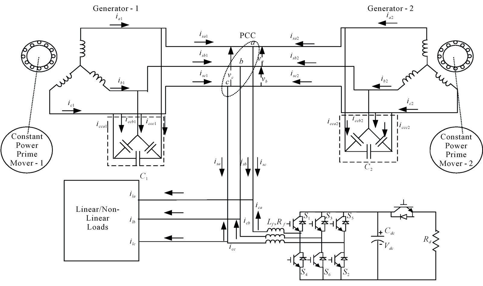
Figure 1. Schematic diagram of a proposed parallel operated IAG system with an improved electronic load controller.
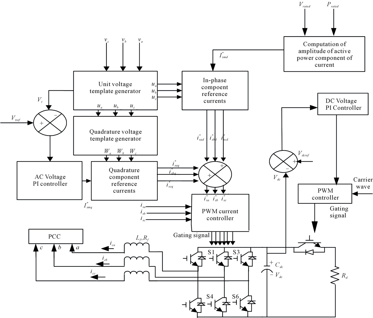
Figure 2. Schematic diagram of control scheme for an improved electronic load controller.
error is processed in the PI voltage controller. The output of the PI (Proportional Integral) controller for AC voltage control loop decides the amplitude of reactive current ( ) to be generated by the controller. Multiplication of quadrature unity amplitude templates (wa, wb and wc) with the output of PI based AC voltage controller (
 ) yields the quadrature component of the reference source currents (
 ,
, and
and ). For a constant power generation, active power component of source currents are fixed at rated value, which is the amplitude of in-phase component of source currents (
 ). Multiplication of in-phase unit amplitude templates (ua, ub and uc) with in phase component of source current (
 ) yields the in-phase component of the reference source currents (
 ,
, and
and ). The sum of instantaneous quadrature and in-phase components of currents is the reference source currents (
 ,
, and
and ), and these are compared with the sensed source currents (
 ,
, and
and ). These current error signals are amplified and these amplified signals are fed to the hystresis controller for generating the PWM signals for IGBTs of VSC.
The excess generated power other than consumer loads is absorbed in the DC chopper fed auxiliary load resistor (Rd) using DC bus PI voltage controller. The DC bus voltage of VSC of the controller is compared with its reference voltage value. The DC bus error voltage is processed in a PI controller. The output of the PI controller is compared with triangular carrier wave to generate gating signal to the DC chopper switch (IGBT).
3. Control Algorithm
Modeling of the control scheme for a 3-leg voltage source converter and a DC chopper switch for voltage and frequency control is given as follows:
3.1. In Phase Component of Reference Source Current
For the constant power application, IAGs should generate constant active power to feed either consumer loads or auxiliary load (Rd) in the controller. For regulating the constant power, in-phase component of reference source current is set equal to the rated amplitude of active power component of current as:
 (1)
(1)
where  is the total generated power (Pgen1 + Pgen2) of IAGs and
  is rated voltage at their terminals.
The instantaneous line voltages at the IAGs terminals (va, vb and vc) are considered sinusoidal and their amplitude is computed as:
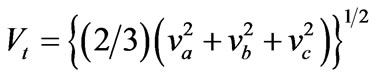 (2)
(2)
The unity amplitude templates having instantaneous value in phase with instantaneous voltage (va, vb and vc), are derived as:
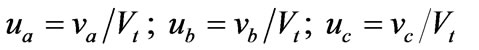 (3)
(3)
Instantaneous values of in-phase components of reference source currents are estimated as:
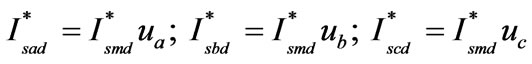 (4)
(4)
3.2. Quadrature Component of Reference Source Current
The AC voltage error Ver at the nth sampling instant is:
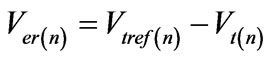 (5)
(5)
where  is the amplitude of reference AC terminal voltage and
  is the amplitude of the sensed threephase AC voltage at the IAGs terminals at nth instant.
The output of the PI controller (I*smq(n)) for maintaining constant AC terminal voltage at nth sampling instant is expressed as:
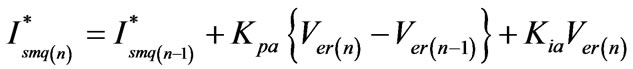 (6)
(6)
where  and
and  are the proportional and integral gain constants of the proportional integral (PI) controller (values are given in Appendix).
  and
and  are the voltage errors in nth and (n-1)th instant and
  is the amplitude of quadrature component of the reference source current at (n – 1)th instant.
The instantaneous quadrature components of reference source currents are estimated as:
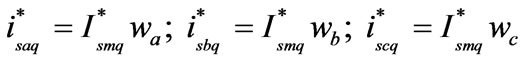 (7)
(7)
where ,
,  and
and  are another set of unit vectors having a phase shift of 90º leading the corresponding unit vectors
 ,
,  and
and  which are given as follows:
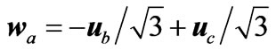 (8)
(8)
 (9)
(9)
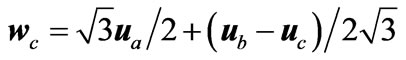 (10)
(10)
3.3. Reference Source Current
Total reference source currents are sum of in-phase and quadrature components of the reference source currents as:
![]() (11)
(11)
![]() (12)
(12)
![]() (13)
(13)
3.4. PWM Current Controller
The reference source currents ,
,  and
and ) are compared with the sensed source currents (
 ,
, and
and ). The current errors are computed as:
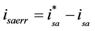 (14)
(14)
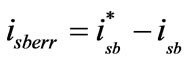 (15)
(15)
 (16)
(16)
These current errors are amplified and compared with fixed frequency (10 kHz) triangular wave generate gating signals for IGBTs of VSC.
3.5. Control for DC Bus Chopper
To maintain the DC bus voltage of VSC constant, the DC voltage error  at nth sampling instant ia calculated as:
 (17)
(17)
where  is the reference DC voltage and
  is the sensed DC link voltage of the CC-VSC.
The output of the PI voltage controller at the nth sampling instant is expressed as:
 (18)
(18)
where  and
and  are the proportional and integral gain constants of the DC bus voltage controller. The PI controller output (
![]() ) is compared with the triangular carrier (
) is compared with the triangular carrier ( ) waveform and its output is fed to the gate of the chopper switch (IGBT) of the controller.
4. Design of the Controller
The detailed design procedure is given for proposed improved electronic load controller which is based on three leg VSC, for a three phase three wire systems.
The parameters of the controller are designed for two IAGs of total rating of 22.5 kW, 415 V, 50 Hz based stand alone pio hydro power generating system. It is reported that for feeding the reactive power in case of 0.8 pf lagging reactive load IAGs required 130% - 160% of rated generated power [8]. Therefore the VAR rating of the controller should be for 22.5 kW generator is around 30 kVAR (133%). Then the apparent power SA is given by.
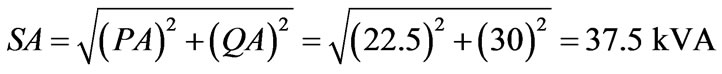
So the current rating of the converter  = 37.5 kVA

Peak value of the current is 
On the basis of above current rating the peak to peak current ripple (consider 5% of peak current) through filter inductor can be estimated as:
ILripplepk-pk = 0.05 * 73.7 = 3.68 A By estimating this current ripple and average value of current, the value of filter inductor, DC link capacitor, value of auxiliary load resistance can be estimated for IELC as follows. Here modulation index (ma) is considered equal to value of ‘1’, ripple through inductor current is 5%, overloading factor (KL) due to transient condition varies from 120% to 180% and switching frequency is of 10 kHz.
The filter inductor, DC link capacitor and voltage, the design of three leg VSC can be calculated similar to Ref [8].
1) Calculation of filter inductor by substituting all values as,
 (19)
(19)
2) The DC link voltage is selected as follows The DC link voltage is selected from eq as (20):
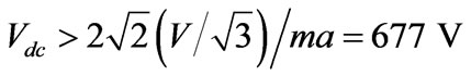 (20)
(20)
For this calculated value of 677 V the nearby round off value of Vdc is selected of 700 V.
The DC link capacitor can be estimated by considering the ripple voltage across it. During the case of unbalance loads, fundamental current flows through the VSC of IELC as well as for compensating second order harmonic, the value of capacitor can be determined by following equations.
Vdc_rippple 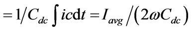 (21)
(21)
where Iavg is the average current flowing through the IELC. This current can be computed considering worst case of load unbalancing for single phase load, for which average current is taken as 90% of r.m.s compensator current (Ic = 52 A).
Iavg = 0.9 * 52 = 46.8 A If one considers voltage ripple in Vdc of order of 2%, thenVdc_rippple = 2% of Vdc = 0.02 * 700 = 14 V Substituting value of Iavg = 46.8 A, ω = 314 r/s, Vdc_rippple = 14 V, the value of Cdc is calculated from Equation (21), as Cdc = 5323 µF.
For this calculated value of Cdc = 5323 µF, a nearby value of 6000 µF is selected for preposed design of IELC.
3) Rating of auxiliary load resistance (Rd) can be calculated as:
Rd = (Vdc)2/PR = (700)2/22500 = 21.77 Ω(22)
Value of Rd is selected of 21Ω for giving wide range of control to the controller.
where PR is the rated power of the generator and is to be absorbed in IELC at zero consumer loads. This calculated value of Rd should be connected in series of a chopper at DC bus of inverter to absorb the rated power.
4) Voltage and current rating of the switches The VSC device voltage and current rating can be calculated as:
Vsw = (Vdc + Vd ) = 745 V(23)
Isw = 1.25 (iLripple(p-p) + Is (peak)) = 96.7 A (24)
Current rating of the chopper switch is computed as Ich = Vdc/Rd = 33.33A(25)
These calculated value and selected value on the basis of the availability of the component are given in Table 1.
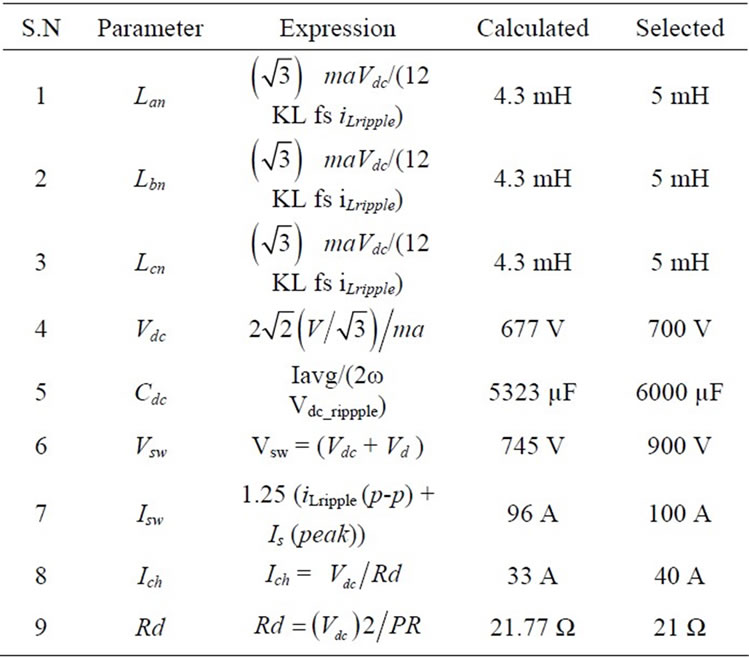
Table 1. Expression, calculation and selection of various components of three leg VSC based IELC.
5. MATLAB Based Modeling
Figures 3-4 show the MATLAB based model of the proposed controller along-with parallel operated isolated asynchronous generators system. The main generating system consists of parallel operated isolated asynchronous generators, excitation capacitors, voltage and frequency controller along-with balanced/unbalanced, linear/non-linear consumer loads. Figure 3 shows the complete model of the proposed electrical generating system while Figures 4(a) and 4(b) show the subsystem VSC control and chopper control. The universal bridge is used to model the voltage source converter for the controller and three phase diode bridge rectifier for non-linear consumer load. The proposed system is modeled using 15kW, 415 V, 50 Hz, Y-connected and 7.5 kW, 415 V, 50 Hz, Y-connected asynchronous machines to operate as IAGs. Individual delta connected capacitor banks having rating of 9 kVAR and 5 kVAR are used for generating the rated voltage at no-load. Simulation is carried out in MATLAB version 7.1 using (ode 23 tb/TR-BDF-2) solver and other relevant data are given in Appendix.
6. Results and Discussion
The developed model of proposed controller for parallel operated IAGs system feeding linear/ nonlinear, balanced/unbalanced loads is simulated and waveforms of the generators voltage (vabc) and currents (iabc1) and (iabc2), capacitor current (icca1, icca2), load current (ilabc), controller current (icabc), terminal voltage (vt), DC link voltage (vdc), frequency (f) and speeds of both generators (w1 and w2) etc are shown in Figures 5-6. For the simulation, a 7.5 kW, 415 V, 50 Hz and 15 kW, 415 V, 50 Hz asynchronous machines have been used as IAGs for parallel operation and parameters are given in Appendix.
6.1. Performance of IAGs-Controller System Feeding Linear Loads
Figure 5 shows the performance of the proposed controller system with balanced/unbalanced delta connected resistive load. At 2.5 sec balanced three-single phase loads each of 7 kW is applied between each phase to phase and then the currents (icabc) drawn by the controller are suddenly reduced to regulate the generators currents, which in turn maintain the system frequency constant. With opening of a single phase load at 2.6 sec and then other phase at 2.7sec, the load becomes unbalanced and an action of the controller is observed, which shows the load balancing aspect of the system. At 2.8 sec the consumer load is fully removed, the auxiliary load absorb

Figure 3. MATLAB based simulation model of proposed electric system.
 (a)
(a)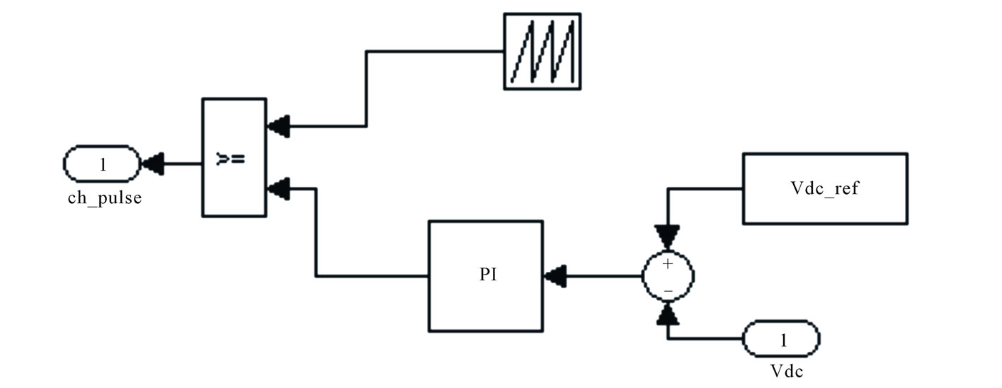 (b)
(b)
Figure 4. (a) Subsystem of VSC control. (b) Subsystem of chopper control.
the full active power generated by the generators, which shows that the controller maintains the generators power, frequency and voltage constant.
6.2. Performance of IAGs-Controller System Feeding Non-linear Loads
Figure 6 shows the performance of parallel operated IAGs-controller system feeding balanced/unbalanced nonlinear loads using three phase diode rectifier with resistive load and L-C filter at its DC side. At 2.6 sec, a balanced non-linear load is applied then the controller currents (icabc) are reduced with in a cycle for regulating the power, frequency and these become non-linear for eliminating harmonic currents. On removal of one phase of the
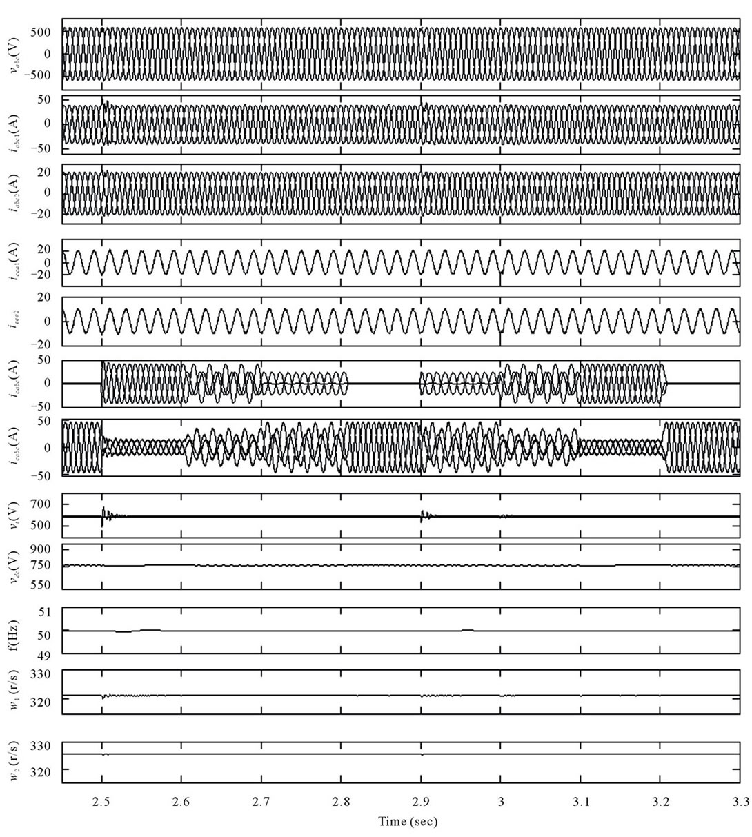
Figure 5. Transient waveforms of parallel operated IAGs with an improved electronic load controller feeding resistive load.
load at 2.75 sec the load becomes unbalanced but the generators currents remain balanced, which shows the load balancing of the controller.
6.3. Power Quality Aspects
Figure 7 and Figure 8 demonstrate performance of the controller as a harmonic eliminator. Here it is observed that due to the non-linear load, harmonics are injected in the supply. At application of around full load, load currents which are having total harmonic distortion (THD) of around 26.30%, are compensated by the controller and THD of terminal voltage, generator-1 current and
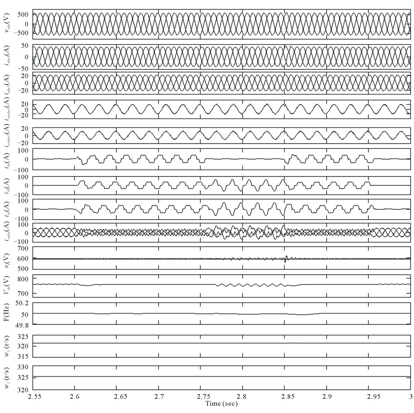
Figure 6. Transient waveforms of parallel operated IAGs with an improved electronic load controller feeding non-linear load.
generator-2 current are observed order of 1.01%, 2.59% and 1.53% respectively as shown in Figure 7. At opening of one phase of the load, the load becomes unbalanced and its current THD is observed to be order of 37.53% as it is shown in harmonic spectra given in Figure 8. Under this condition, the THD of terminal voltage, generator-1 current and generator-2 current are observed of the order of 1.27%, 1.59% and 1.39% respectively, which is much less than 5%, the limit imposed by IEEE – 519 Standard.
6.4. Performance of IAGs-Controller System Feeding Induction Motor Loads
Figure 9 shows the performance of the proposed controller with application/removal of a load torque on the induction motor load. Different transient waveforms of generator voltage (vabc) and generator currents (iabc1 and iabc2), excitation capacitor currents (icca), load currents (ilabc), speed of the induction motor load (wm), load torque (TL), controller currents (icabc), amplitude of terminal voltage (Vt), the DC link voltage (Vdc), frequency
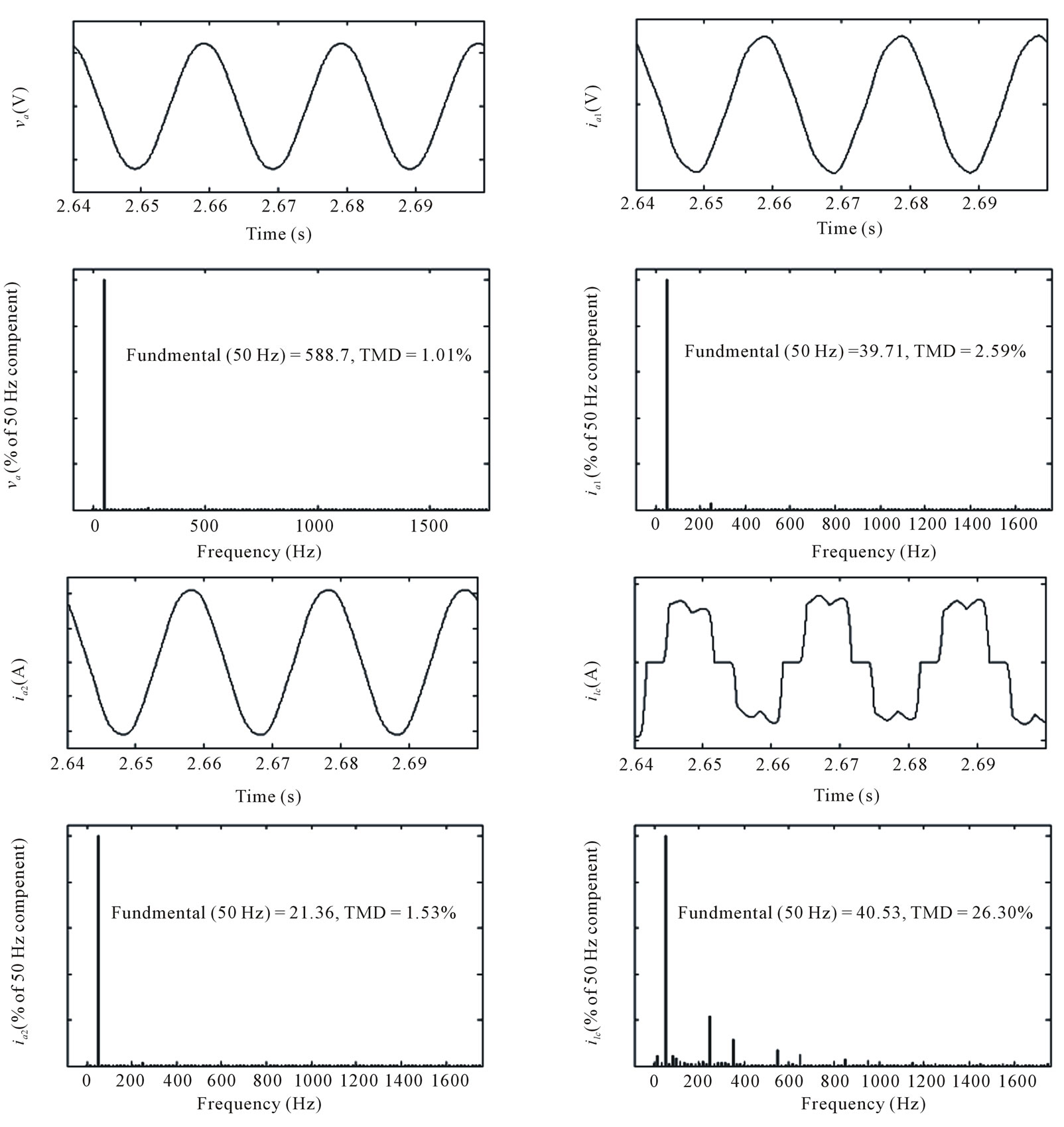
Figure 7. Waveforms and harmonic spectra of generated voltage (va) Generator-1 current (ia1) Generator-2 current (ia2) Consumer load current (ilc) under the condition of balanced non-linear load.
(f), speed of the generators (wg1, wg2) and motor applied load torque (TL), power (Pgen1, Pgen2, Pload and Pdump) etc are shown to study the performance of the IELC.
At 2.4 s the load torque is applied on the running mo tor as shown in Figure 9 then the current in the stator winding of the motor is increased (ilabc) and the current (icabc) drawn by the proposed controller is reduced due to action of the controller while voltage and current at the generator terminal remain constant. At 2.75 s when the load torque on the motor is removed the current drawn by the motor is reduced and additional generated power is absorbed by the auxiliary load of the proposed controller. In this way the controller functions as voltage and frequency controller.
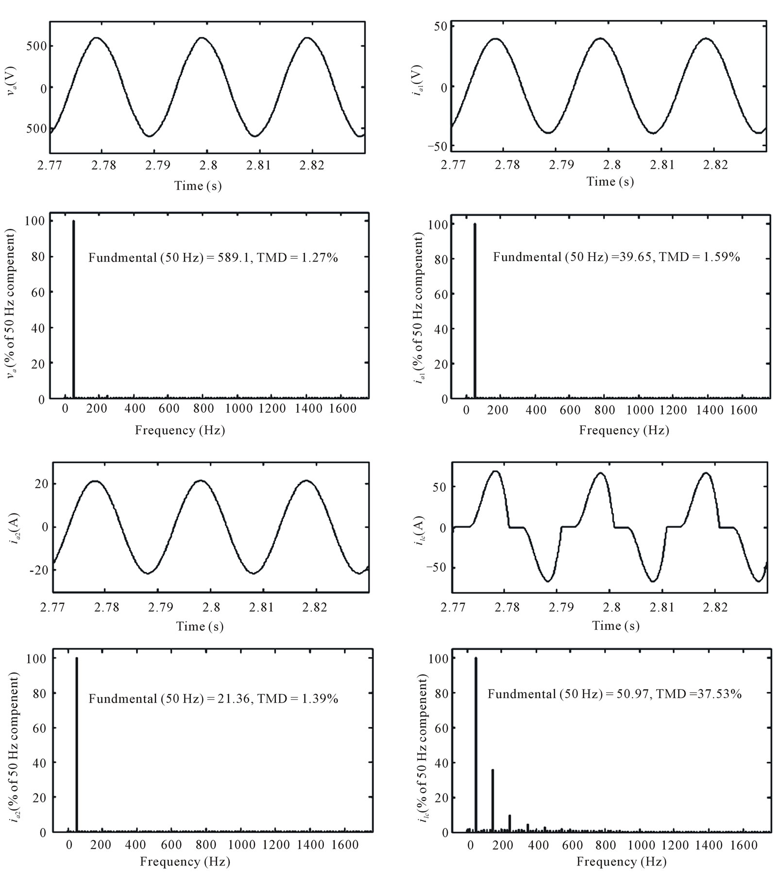
Figure 8. Waveforms and harmonic spectra of generated voltage (va) Generator-1 current (ia1) Generator-2 current (ia2) Consumer load cur rent (ilc) under the condition of un-balanced non-linear load.
7. Conclusion
The performance of the proposed controller has been demonstrated for parallel operated isolated asynchronous generators in constant power application driven by uncontrolled pico hydro turbines. It has been observed that the controller is having capability of voltage and frequency regulation along with harmonic compensation
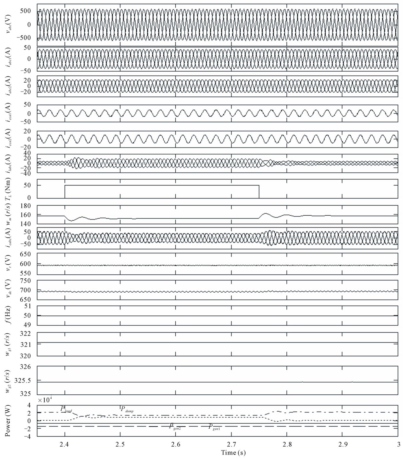
Figure 9. Transient waveforms of parallel operated IAGs with an improved electronic load controller for application and removal of load torque on an Induction motor load.
and load balancing. Moreover, it has resulted in a single point operation of the generators through regulating the voltage, frequency, the load and capacitors to constant value.
REFERENCES
- H. M. B. Metwally, “New Self-Excited Variable Speed Constant Frequency Generator for Wind Power Systems,” Energy Conversion and Management, Vol. 41, No.13, September 2000, pp 1405-1417. doi:10.1016/S0196-8904(99)00170-3
- J. M. Chapallaz, D. G. P. Eichenberger and G. Fischer, “Manual on Induction Motors Used as Generators,” Vieweg (Braunschweig), 1992.
- B. Singh, “Induction Generator—A Prospective,” Electric Machines and Power Systems, Vol. 23, No. 2, 1995, pp. 163-177. doi:10.1080/07313569508955615
- E. Suarez and G. Bortolotto, “Voltage—Frequency Control of a Self Excited Induction Generator,” IEEE Transactions on Energy Conversion, Vol. 14, No. 3, September 1999, pp. 394-401. doi:10.1109/60.790888
- B. Singh, S. S. Murthy and S. Gupta, “Transient Analysis of Self Excited Induction Generator with Electronic Load Controller Supplying Static and Dynamic Loads,” IEEE Transactions on Industry Applications, Vol. 41, No. 5, September 2005, pp. 1194-1204. doi:10.1109/TIA.2005.855047
- B. Singh, S. S. Murthy and S. Gupta, “Analysis and Implementation of an Electronic Load Controller for a SelfExcited Induction Generator,” IEE Proceedings—Generation Transmission and Distribution, Vol. 151, No.1, January 2004, pp. 51-60. doi:10.1049/ip-gtd:20040056
- R. Bonert and S. Rajakaruna, “Self-Excited Induction Generator with Excellent Voltage and Frequency Control,” IEE Proceedings—Generation, Transmission and Distribution, Vol. 145, No. 1, January 1998, pp. 33-39. doi:10.1049/ip-gtd:19981680
- B. Singh, S. S. Murthy and S. Gupta, “Analysis and Design of Electronic Load Controller for Self-Excited Induction Generators,” IEEE Transactions on Energy Conversion, Vol. 21, No. 1, March 2006, pp. 285-93. doi:10.1109/TEC.2005.847950
- B. Singh, S. S. Murthy and S. Gupta “A Voltage and Frequency Controller for Self-Excited Induction Generators,” Electric Power Components and Systems, Vol. 34, No. 2, February 2006, pp 141-157.
- B. Singh, S. S. Murthy and S. Gupta, “An Improved Electronic Load Controller for Self-Excited Induction Generator in Micro-Hydel Applications,” Proceedings of IEEE Industrial Electronics Conference (IECON), Vol. 3, 2-6 November 2003, pp 2741-2746.
- H. S. Timorabadi, “Voltage Source Inverter for Voltage and Frequency Control of a Stand-Alone Self-Excited Induction Generator,” Canadian Conference on Electrical and Computer Engineering, Ottawa, 2007, pp. 2241- 2244.
- J. M. Ramirez, T. M. Emmanuel, “An Electronic Load Controller for the Self-Excited Induction Generator,” IEEE Transaction on Energy Conversion, Vol. 22, No. 2, June 2007, pp. 546-548. doi:10.1109/TEC.2007.895392
- J. A. Barrado and R. Grino, “Voltage and Frequency Control for a Self Excited Induction Generator Using a 3-Phase 4-Wire Electronic Converters,” Proceedings of 12th International IEEE Power Electronics and Motion Control Conference, August 2006, pp. 1419-1424.
- T. Ahmad, M. Nakaoka and K. Nishida, “Advanced Active Power Filter for Renewable Energy Application of Stand Alone Induction Generator,” Proceedings of 32nd Annual Conference on IECON 2005, November 2005, pp. 756-761.
- L. Wang and C. H. Lee, “Dynamic Analysis of Parallel Operated Self Excited Induction Generator Feeding an Induction Motor Load,” IEEE Transactions on Energy Conversion, Vol. 14, Vol. 3, September 1999, pp. 479- 485.
- C. Chakraborty, S. N. Bhadra and A. K. Chattopadhyay, “Analysis of Parallel Operated Self-Excited Induction Generators,” Proceedings of IEEE international Conference on Power Electronics Drive and Energy Systems (PEDES’96), New Delhi, December 1996, pp. 463-469.
- L. B. Shilpkar, B. Singh and K. S. P. Rao, “Transient analysis of parallel operated self-excited induction generators,” Proceedings of IEEE International Conference on Power Electronics Drive and Energy Systems (PEDES’96), New Delhi, December 1996, pp. 470-476.
- C. Chakraborty, S. N. Bhadra, M. Ishida and A. K. Chattopadhyay, “Performance of Parallel Operated Self Excited Induction Generators with the Variation of Machine Parameters,” Proceedings of IEEE Conference on Power Electronics and Drive Systems, July 1999, pp. 86-91.
- A. H. Al-Bahrani and N. H. Malik, “Voltage Control of Parallel Operated Self Excited Induction Generators,” IEEE Transactions on Energy Conversion, Vol. 8, No. 2, June 1993, pp. 236-242. doi:10.1109/60.222710
- I. Tamrakar, L. B. Shilpkar, B. G. Fernandes and R. Nilsen, “Voltage and Frequency Control of Parallel Operated Synchronous Generator and Induction Generator with STATCOM in Micro Hydro Scheme,” Proceedings of IET—Generation, Transmission and Distribution, Vol. 1, No. 5, September 2007, pp. 743-750.
Appendix
1. The Parameters of 15 kW, 415 V, 50 Hz, Y-Connected, 4-Pole Asynchronous Machine are Given Below
Rs = 0.58 Ω, Rr =0.78 Ω, Xlr= Xls= 2.52 Ω, J = 0.23 kg/m2
Lm = 0.22 Im < 2.8
Lm = 0.0001Im2 – 0.0138Im+0.27 2.8 < Im < 14.2
Lm = 0.1 Im > 14.2
2. The Parameters of 7.5 kW, 415 V, 50 Hz, Y-Connected, 4-Pole Asynchronous Machine are Given Below
Rs = 1 Ω, Rr = 0.77 Ω, Xlr= Xls= 1.5 Ω, J = 0.1384 kg/m2
Lm = 0.134 (Im < 3.16)
Lm = 9e – 5Im2 – 0.0087Im + 0.1643 (3.16 < Im < 12.72)
Lm = 0.068 (Im>12.72)
3. Controller Parameters
Lf = 5 mH, Rf = 0.1 Ω, Cdc = 6000 µF and Rd = 21 Ω
Kpa = 0.13, Kia = 0.032, Kpp = 0.15, Kpi = 0.01
4. Consumer Loads
Resistive load 7.5 kW single phase loads (line to line)
Non-linear load 20 kW with 1000 µF capacitor and 2 mH inductor at DC end of diode bridge rectifier
5. Prime Mover Characteristics for 15 kW Machine
Tsh = K1 – K2 wr ; K1 = 6500, K2 = 40
6. Prime Mover Characteristics for 7.5 kW Machine
Tsh = K1 – K2 wr,; K1 = 3310, K2 = 10
7. The parameter for Three Phase 415 V, 50 Hz, 7.5 kW Induction Motor Load
Rs = 1 Ω, Rr = 0.77 Ω, Xlr= Xls= 1.5 Ω, J = 0.1384 kg/m2