Int'l J. of Communications, Network and System Sciences
Vol. 6 No. 5 (2013) , Article ID: 31327 , 7 pages DOI:10.4236/ijcns.2013.65023
Performance of AF Relay Networks with Multiple Relays and Multiple Antennas at Destination Using MRC Combining*
Department of Computer Science and Engineering, Graduate School of Engineering Nagoya, Institute of Technology, Nagoya, Japan
Email: cja17636@stn.nitech.ac.jp, satosi.ri@gmail.com, iwanami@nitech.ac.jp
Copyright © 2013 Solimanzoy Fayeqa Haider et al. This is an open access article distributed under the Creative Commons Attribution License, which permits unrestricted use, distribution, and reproduction in any medium, provided the original work is properly cited.
Received March 18, 2013; revised April 12, 2013; accepted May 6, 2013
Keywords: AF Relay; MRC; Diversity; Multiple Relays; Multiple Antennas
ABSTRACT
Cooperative networking schemes in wireless networks provide cooperative diversity gain using differently located antennas that combat fadings induced by multipath propagation. In this paper, we present the optimal weight design for the destination in AF (Amplify and Forward) relay system, where the optimally designed MRC (Maximum Ratio Combining) is employed at the destination for S→D link (direct link between source and destination) and R→D links (indirect links between relays and destination). We investigate the BER performance of 1S→NR→LD system composed of one source, N relay nodes equipped with single antenna and one destination node equipped with L antennas, which also includes 1S→1R→LD and 1S→NR→1D. Simulation and numerical results are presented to verify our analysis.
1. Introduction
Wireless relaying is a promising solution to overcome the channel impairments and provides high data rate coverage that appears for the next generation mobile communications. Cooperative diversity networks have recently been proposed as a way to form virtual antenna arrays where neighboring relay nodes assist the source to send the information to the destination for achieving spatial diversity [1-3].
Cooperative relaying has drawn considerable attention as an efficient strategy to enhance communication reliability in flat fading environments. Without a sort of signal regeneration like in Detect & Forward or Decode & Forward, an AF relay system simplifies relaying operation and is suited to many actual applications with less complexity [4-8].
In this paper, we derive the MRC weights [9] at destination for the dual hop wireless communication system equipped with a source, multiple AF relays and multiple receive antennas at destination over flat Rayleigh fading channels. We also assume that the source node has single antenna, each relay has single antenna and the destination node has multiple receive antennas. We compare the BER performance in case of QPSK modulation by varying the number of relays and receive antennas at destination. Such a comparison is considered to be novel. Although the channels between different nodes are modeled as flat Rayleigh fading channels, this means that each channel is regarded as a subcarrier channel of OFDM modulation. The remainder of this paper is organized as follows: Section 2 presents the system model. In Section 3, we derive the optimal MRC weights at destination by using Lagrange multiplier method and analyze the receive SNR at destination. We show the simulation results in Section 4. The conclusions are given in Section 5. We illustrate some of the notations as follows: vectors and matrixes are expressed by bold letters, we use  and
and  as transpose of matrix, conjugate of complex variable and transpose conjugate of matrix, respectively.
2. System Model
We consider a dual-hop cooperative network system consisting of a source with single antenna,  relays equipped with single antenna, and a destination having
 ![]() received antennas as shown in Figure 1. Assuming the time division multiplexing scheme is employed, in the first time slot, the source transmits the signal to the relays through the channels denoted as
received antennas as shown in Figure 1. Assuming the time division multiplexing scheme is employed, in the first time slot, the source transmits the signal to the relays through the channels denoted as ,
, 
 (
( links) and to the destination through
  (
( link) simultaneously. In the k-th time slot
 , the j-th relay forwards the amplified version of the received signal to the destination through
 ![]() (R→D link).
(R→D link).
In this paper, we assume that the elements of  and
and ![]() are i.i.d. (independently and identically distributed) complex Gaussian random variables, because each flat Rayleigh channel corresponds to a subcarrier channel of OFDM modulation and OFDM can convert the quasi-static frequency selective Rayleigh fading channel to the flat Rayleigh fading channel at each subcarrier.
are i.i.d. (independently and identically distributed) complex Gaussian random variables, because each flat Rayleigh channel corresponds to a subcarrier channel of OFDM modulation and OFDM can convert the quasi-static frequency selective Rayleigh fading channel to the flat Rayleigh fading channel at each subcarrier.
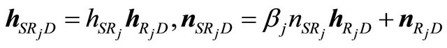
The receive signal  at the j-th relay and the receive signal vector
  at the destination are expressed as
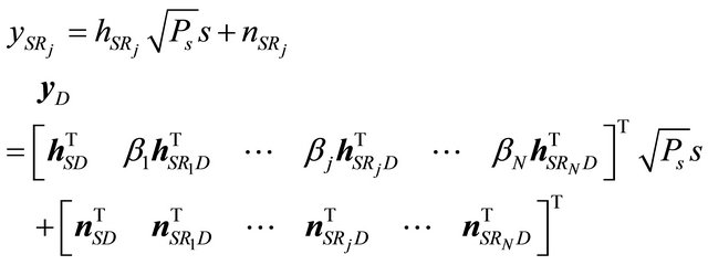 (1)
(1)
where  is the transmit power at source,
 . The elements of
  and
and  are assumed to be i.i.d zero mean complex Gaussian random variable. The variance of
 is given by
 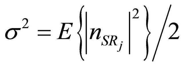 and
and  is the amplification factor at the j-th relay.
3. Optimal Weight Design at Destination
3.1. Optimal Weight Design with MRC
In this section, we derive the optimal combining weights at destination by maximizing the SNR under the power constraint. We assume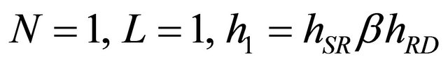 and
and . We also assume that
  and
and  are the receive weights corresponding to
 ![]() and
and  respectively. This is regarded as the SIMO (Single-Input MultipleOutput) case as shown in Figure 2.
The combined signal at destination is expressed by
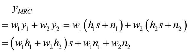 (2)
(2)
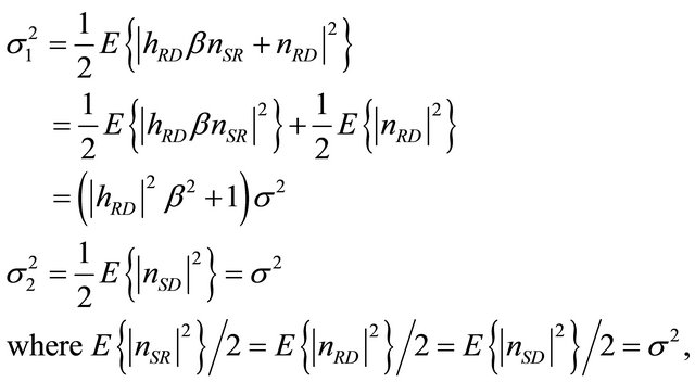
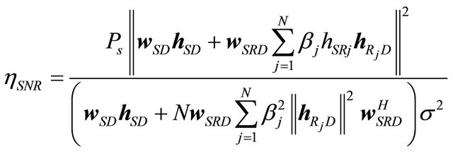
The SNR at destination can be written as where we assume that 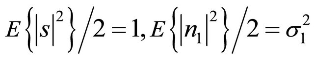
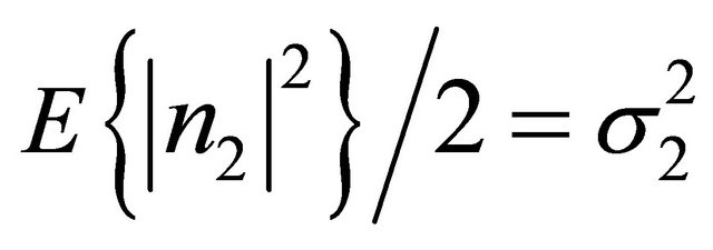 . Under the constraint condition of
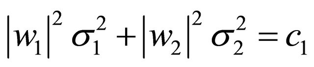 in the denominator in (3) where
 ![]() is the arbitrary real constant, and by introducing Lagrange multiplier method, we obtain objective function to be maximized as
is the arbitrary real constant, and by introducing Lagrange multiplier method, we obtain objective function to be maximized as
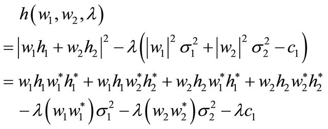 (4)
(4)
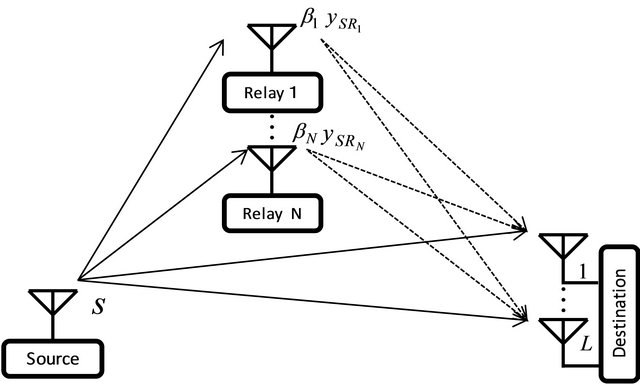
Figure 1. System model of AF relay network.
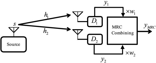
Figure 2. SIMO network using MRC combining.
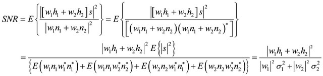 (3)
(3)
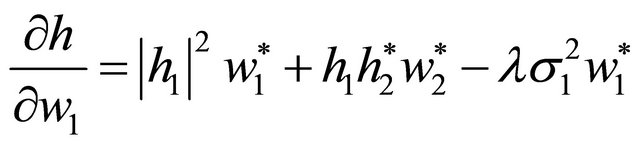
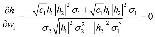
By differentiating  with respect to
  and putting the result to zero, we get
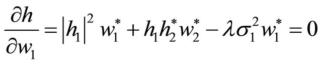 (5)
(5)
From (5) we obtain
 (6)
(6)
Also by differentiating  with respect to
 , we obtain
 (7)
(7)
Accordingly we have
 (8)
(8)
From (6) ~ (8), ![]() is calculated as follows
is calculated as follows
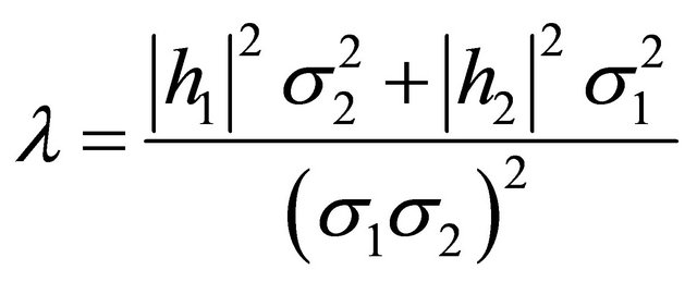 (9)
(9)
Also using (6) and (7), we derive
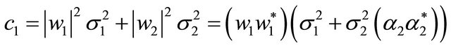 (10)
(10)
 (11)
(11)
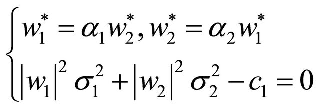
From (11), we obtain
or
 (12)
(12)
By using the symmetry condition, we also obtain
or
 (13)
(13)
At this stage, the ambiguity remains in the determination of  and
and .
.
If we assume
 and
and
 then
then
 (14)
(14)
By inserting  and
and  into (14), we get
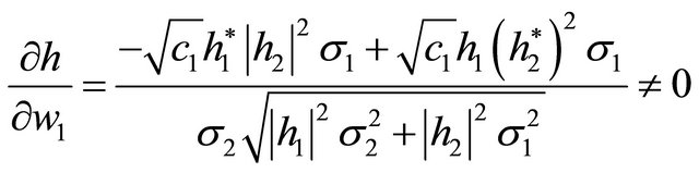 (15)
(15)
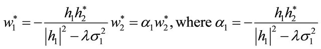
As the weights do not satisfy the original differentiation condition in (5), these weights are not the solution.
On the other hand, if we assume
 and
and
 , then
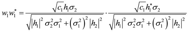
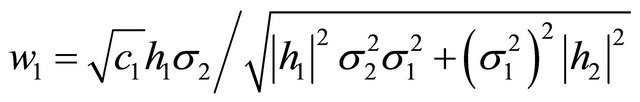
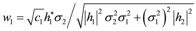
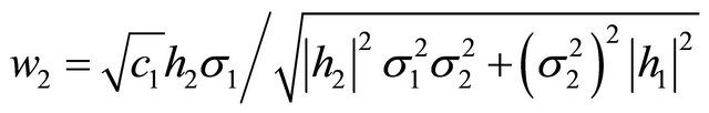
 (16)
(16)
As the above weights satisfy the differentiation condition in (5), these weights are the solutions for MRC weights.
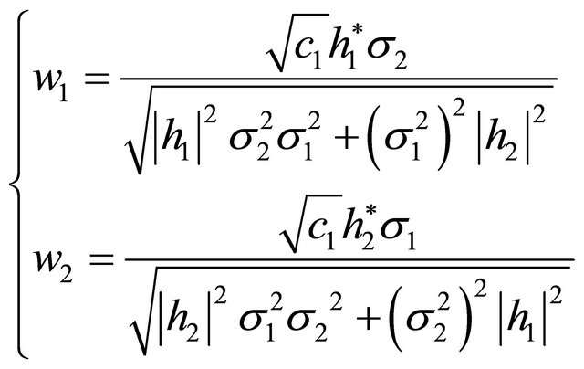 (17)
(17)
Since above two weights shown in (17) satisfy (8), they are the optimal weights for our SIMO system modeled in Figure 2.
Returning to the beginning of this section, we let the receive weight for  link by
  and the receive weight for the
  link by
  respectively. Also by letting
  and
and , we get
and  and
and  are independent of each other.
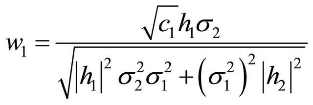
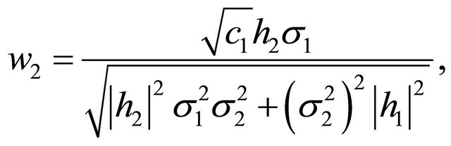
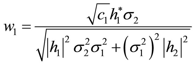
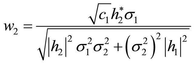
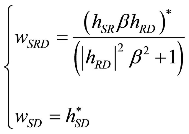
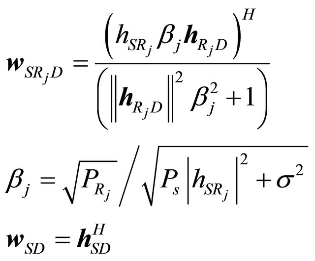
The optimal combining weights at destination for  link and
  link can be written as
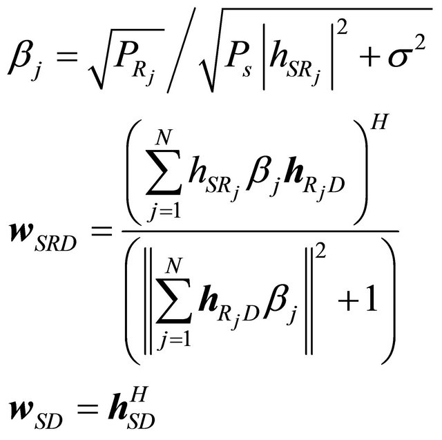
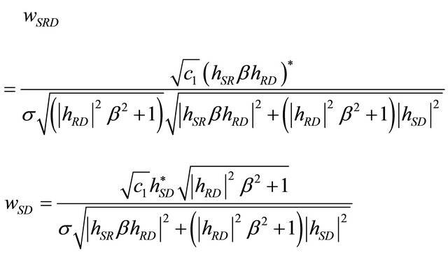 (18)
(18)
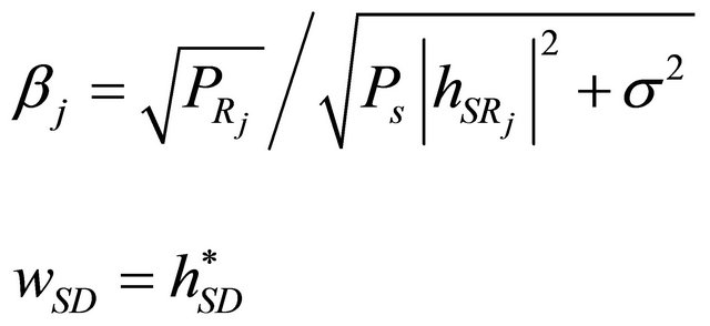
where the AF gain is 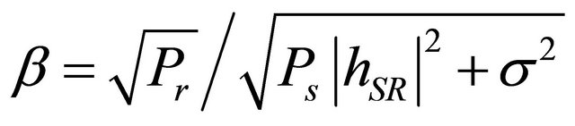 and
and 
is the transmit power at relay node, and further by assuming the arbitrary real constant ![]() as
as
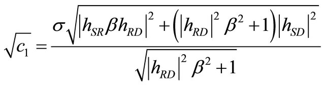 (19)
(19)
We obtain
 (20)
(20)
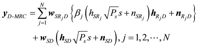
Then at destination the combined signal is given by
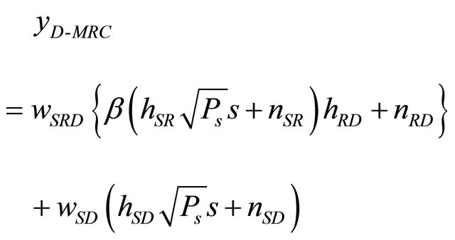 (21)
(21)
We can also obtain the AF gain and receive weight corresponding to each  link where the number of relays is
  and
and .
.
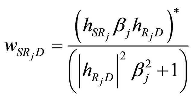 (22)
(22)
 (23)
(23)
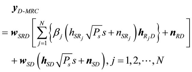
The combined signal at destination in case of multiple relays is expressed as
 (24)
(24)
Similarly, the AF gains and weights in the case of multiple relays with  and multiple receive antennas at destination with
  can be expressed as
 (25)
(25)
 (26)
(26)
The above derivations are all based on using  time slots, i.e., each relay consumes one time slot for each transmission from relay to destination.
Now let us consider the case of using 2 time slots. In other words, the multiple relays retransmit signals to the destination at the same time, where the channels between relays and receive antennas at destination become  MIMO channels. The receive signal vector
  at the destination can be rewritten as
 (27)
(27)
and the AF gains and receive weights are expressed as
 (28)
(28)
3.2. Analysis of SNR at Destination
In this section, we firstly analyze the SNR at destination in the case of  time slots. The instantaneous SNR at destination can be expressed as
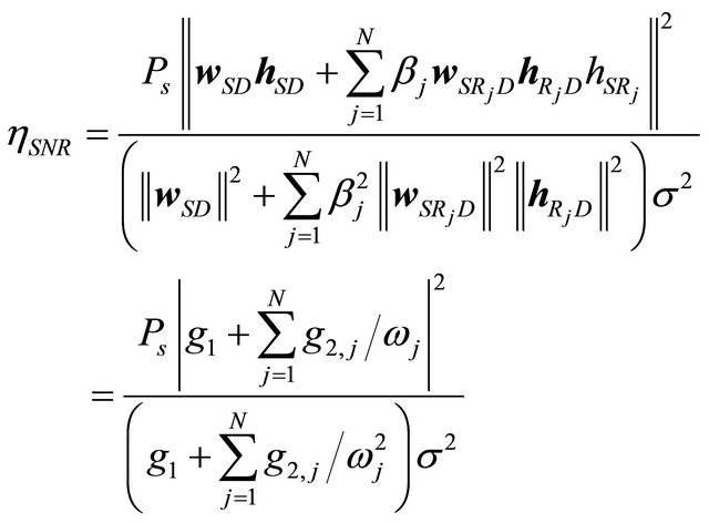 (29)
(29)
where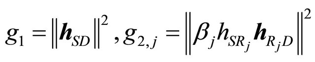 and
and 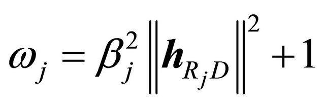 .
.
We firstly consider the  links (without the consideration of
  links), the instantaneous SNR at each receive antenna is the increasing function on
  (
( and
and ). In the similar way, when
  is not considered, the instantaneous SNR at each receive antenna is also increasing function on the number of receive antenna. Therefore, we can obtain the higher
 ![]() when we increase the receive antennas at destination.
when we increase the receive antennas at destination.
Next, we simply analyse the instantaneous SNR at destination for the case of 2 time slots.
 (30)
(30)
It is noticed that we cannot obtain more ![]() improvements as the number of relay is increased. This is similar to the MIMO case where we increase the transmit antennas and the same signal is transmitted. Therefore, we know that using different
improvements as the number of relay is increased. This is similar to the MIMO case where we increase the transmit antennas and the same signal is transmitted. Therefore, we know that using different  time slots and increasing the receive antennas at the destination can obtain the instantaneous SNR improvement.
4. Simulation Results
In this section we show the computer simulation results under the simulation conditions as shown in Table 1. Firstly, in Case 1, we consider the situation where using the 1st time slot the transmissions from source to relay and from source to destination are made, and using time slot 2 the transmissions from relays to destination are done simultaneously. In Case 1, we also consider the following three configurations. 1) A source, a relay and a destination with multiple receive antennas; 1S→1R→LD. 2) A source, multiple relays  and a destination with single receive antenna; 1S→NR→1D. 3) A source, multiple relays
  and a destination
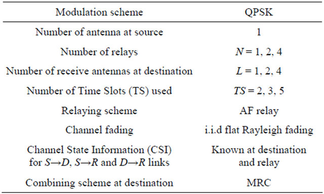
Table 1. Simulation parameters.
with L receive antennas; 1S→NR→LD. Then, in Case 2, we consider the situation where each relay consumes one time slot.
We compare the BER versus receive SNR per a receive antenna at destination using 2, 3 and 5 time slots, which corresponds to the number of relays 1, 2 and 4 respectively. The corresponding MRC weights in 3.1 are used at the destination.
Figure 3 shows the BER improvement for increasing the number of receives antennas at destination. It is noticed that BER improvement can be obtained because we increase the receive antennas at the destination. This is similar to the case of SIMO (Single-Input MultipleOutput).
Figure 4 shows the BER improvement of increasing the number of time slots when multiple relays and single antenna at destination are used. By increasing the number of time slots assigned for each relay to destination link, the MRC works and the large improvement of SNR is obtained. From the comparisons among 1 × 1 × 1, 1 × 2 × 1, 1 × 4 × 1 with using 2, 3, and 5 time slots respectively, we can also obtain the diversity gain, which is the same as the configuration in Figure 3. But it is noticed that increasing the number of receive antennas at destination outperforms increasing the number of relays. This is because the effect of MRC for the S→D link contributes more than combining many time slots for the R→D link. Also since using many time slots leads to the degradation of transmission rate, we can say the BER performances shown in Figure 3 are more preferable and efficient than Figure 4, when comparing Figure 3 with Figure 4.
Figure 5 shows the cases where we use multiple relays, two receive antennas at destination and multiple time slots, i.e.,  and 5. The BER improvement (diversity gain) is obtained with the increase of number of relays and time slots. From the comparison between the configurations of 1 × 1 × 2 using 2 time slots and the one of 1 × 2× 2 using 3 time slots, about 3.5 dB improvements can be obtained at the BER of 10−5. Also from the comparison between 1 × 1 × 2 using 2 time slots and 1 ×
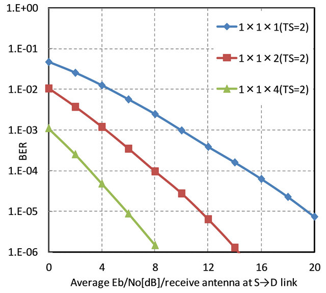
Figure 3. Performance comparison of single relay and multiple receive antennas at destination using 2 time slots.
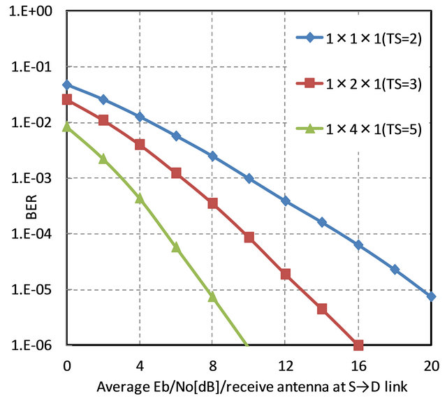
Figure 4. Performance comparison of multiple relays and single antenna at destination using 2, 3 and 5 timeslots.
4 × 2 using 5 time slots, about 6 dB improvements can be observed at the BER of 10−5.
Through Figures 3-5, we could show that the increase of the number of receive antenna at destination and/or the number of time slots has the enormous improvement of BER results.
5. Conclusion
![]() In this paper we derived the optimal MRC weights of dual-hop AF cooperative relay system. We presented the BER performances with MRC weights at destination for various combinations of number of relays and number of receive antennas at destination. The BER performance
In this paper we derived the optimal MRC weights of dual-hop AF cooperative relay system. We presented the BER performances with MRC weights at destination for various combinations of number of relays and number of receive antennas at destination. The BER performance
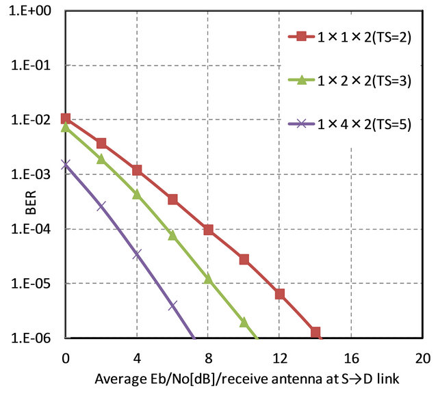
Figure 5. Performance comparison of multiple relays and multiple receive antennas at destination using 2, 3 and 5 timeslots.
can be largely improved by increasing the number of receive antennas at destination or the number of time slots used for the transmission from relays to destination. This observation seems to be caused from the MRC effect at the destination. The BER performance of multiple receive antennas at destination is better than the multiple relay configuration. This seems due to the existence of increased amplified and forwarded noises from multiple relays to destination. So we can get the best BER results using the proposed MRC gains when the number of time slots is taken as  with
with ![]() receive antennas at destination.
receive antennas at destination.
REFERENCES
- M. Dohler and Y. H. Li, “Cooperative Communications: Hardware, Channel & PHY,” John Wiley & Sons, Ltd, Chichester, 2010.
- J. N. Laneman, D. N. C. Tse and G. W. Wornell, “Cooperative Diversity in Wireless Networks-Efficient Protocols and Outage Behavior,” IEEE Transactions of Information Theory, Vol. 50, No.12, 2004, pp. 3062-3080. doi:10.1109/TIT.2004.838089
- D. G. Brennan, “Linear Diversity Combining Techniques,” Proceedings of the IEEE, Vol. 91, No. 2, 2003, pp. 331- 356. doi:10.1109/JPROC.2002.808163
- M. O. Hasna and M. S. Alouini, “End-to-End Performance of Transmission Systems with Relay over RayleighFading Channel,” IEEE Transactions on Communications, Vol. 2, No. 6, 2003, pp. 1126-1131.
- K. G. Seddik, A. K. Sadek, W. Su and K. J. R. Liu, “Outage Analysis of Multi-Node Amplify-and-Forward Relay Networks,” IEEE Wireless Communication and Networking (WCNC2006), Vol. 2, Las Vegas, 3-6 April 2006, pp. 1184-1188.
- K. G. Seddik, A. K. Sadek, W. Su and K. J. R. Liu, “Outage Analysis and Optimal Power Allocation for MultiNode Relay Networks,” IEEE Signal Processing Letters, Vol. 14, No. 6, 2007, pp. 377-380.
- Bletsas, H. Shin and M. Z. Win, “Outage Optimality of Opportunistic Amplify-and-Forward Relaying,” IEEE Communications Letters, Vol. 11, No. 3, 2007, pp. 261-263. doi:10.1109/LCOMM.2007.061589
- H. Shin and J. B. Song, “MRC Analysis of Cooperative Diversity with Fixed-Gain Relays in Nakagami-m Fading Channels,” IEEE Transactions on Wireless Communication, Vol. 7, No. 6, 2008, pp. 2069-2074. doi:10.1109/TWC.2008.070812
- B. Holter and G. E. Øien, “The Optimal Weights of a Maximum Ratio Combiner using an Eigenfilter Approach,” Proceedings of 5th IEEE Nordic Signal Processing Symposium, Hurtigruten, 4-6 October 2002.
NOTES
*This study has been supported by the Scientific Research Grant-in-aid of Japan No. 24560454.