Wireless Sensor Network
Vol.5 No.8(2013), Article ID:36361,7 pages DOI:10.4236/wsn.2013.58018
Design and Implementation of Remotely Controlled Vehicle Anti-Theft System via GSM Network
1Department of Electrical/Electronics Engineering, Afe Babalola University, Ado-Ekiti, Nigeria
2Department of Computer Engineering, Afe Babalola University, Ado-Ekiti, Nigeria
3Federal Ministry of Communication, Abuja, Nigeria
Email: tolulopett@yahoo.com, ask4pat2001@yahoo.com, omitolasesun@yahoo.com, oladayoadedokun@yahoo.com
Copyright © 2013 T. T. Oladimej et al. This is an open access article distributed under the Creative Commons Attribution License, which permits unrestricted use, distribution, and reproduction in any medium, provided the original work is properly cited.
Received June 17, 2013; revised July 13, 2013; accepted July 24, 2013
Keywords: CODEC—Coder and Decoder; GSM—Global System for Mobile Telecommunication; GPRS—General Packet Radio Service; MODEM—Modulator and Demodulator; SMS—Short Messaging Service
ABSTRACT
The purpose of this paper is to build a secured and reliable vehicle anti-theft system which will have the ability to access the vehicle subsystems from a remote location where there is GSM network. And also, the design method involves the interfacing of GSM/GPRS modem module with the vehicle ignition subsystem, and the test result shows that it performs some control actions on the vehicle subsystems from a mobile phone, having taken the advantage of the wide coverage area of some GSM networks. Hence the topic is “Remotely Controlled Vehicle Anti-theft System via GSM Network”.
1. Introduction
The rate of increase in car theft in this part of the world has reached an alarming rate. In the rave of this development, engineers in this country have been performing researches aimed at providing a lasting solution to this endemic act [1]. This research team in an attempt to proffer a lasting solution thought of exploring the GSM technology coupled with some digital control techniques as possible remedy.
The implementation is divided into two subsystems: the remote access link and the vehicle subsystems.
The system can be controlled from anywhere in the world once there is GSM coverage. Although previous work involving tracking of vehicle location was done via the internet. The use of the internet was only restricted to places where there are internet access facilities. However, this system was only explored to track down the exact location of a vehicle but not to demobilize the vehicle from a distant place.
Instead of the embedded web server used by previous designs to gain access through the internet, this present design employs the use of a GSM/GPRS modem module to gain access to the vehicle subsystems.
The importance of this design cannot be over emphasized since it helps to reduce the rate of vehicle theft within our society.
For instance, when there is an intruder into the vehicle, the system will immediately and automatically send out emergency warning signals to the user’s phone, reporting the status of the car and preventing the car from being stolen.
In case of hijacking, the driver can leave the car safely, and then use any phone to send out some commands and remotely cut off power or gasoline supply, so as to stop the car from running and get back the car easily. In such case, the vehicle snatcher will not be in a position to harm the vehicle owner.
Car security system has been very popular in recent times and widely used in most cars and automobiles owned by companies, business organizations and even by some private individuals who can afford the cost. The most common automobile security system has been the manually operated demobilizer. Few of the many automotive theft-prevention systems allow a vehicle to start and temporarily run before disabling a critical component, such as the fuel or ignition system. This type of shutdown sequence is not very confusing and the system could possibly be overcome by the thief (National Motor Vehicle Theft Reduction Council, 2007) [1].
This design is a theft deterrent system that simulates problems in motor vehicles. On engine startup, this system allows normal engine operation for a random time duration during which it can be deactivated. The device is not an alarm system, but can function well in conjunction with any alarm device.
Whenever an unauthorized use is detected, a digital controller randomly generates a unique controlling signal with random timing variations that is communicated to the remote receiving subsystem interface units. These units can be connected in series with vital vehicle subsystem components in order to interfere with typical subsystem component operation, thereby inducing the illusion of an actual vehicle problem severe enough to inhibit vehicle drivability. This system allows unique implementation by locating disabling receivers on any variety of vital vehicle subsystems, presenting thieves with multiple unknowns specific to each vehicle. Hence, there is no chance for a pattern to be developed and very little possibility that the device will be recognized by an unauthorized operator (FreePatentsOnline, 2004-2007) [2].
This system consists of several components coupled with motor vehicle subsystems. The heart of the system is the GSM/GPRS modem module which integrates the capability of a microcontroller. This module supervises the entire system, communicating with one or more remote disabling receivers (mobile phone), which act as the interface circuitry between the controller and the motor vehicle subsystem. The onboard controller performs the generation of random control information signals. A variety of methods can be used to generate the random control information signals, including receiving a radio frequency, using digital logic components, or programming a micro-controller, in order to provide a random control information signal (FreePatentsOnline, 2004-2007) [2].
The functionality of the system is based on the ignition keyswitch and anti-hijacking output, in addition to an input circuit. The keyswitch input simply connects the battery to the coil ignition system of the vehicle.
2. Design Methodology
The complete setup for the remotely controlled vehicle anti-theft system via GSM network was designed and constructed in modules and then the subsystems integrated. The overall system architecture and hardware architecture are depicted in Figures 1 and 2 respectively.
A terminal emulation program (HyperTerminal) was utilized on the PC. Various Windows Operating Systems are shipped with the HyperTerminal software. Several equivalent programs are also available such as the freeware Tera Term software but the HyperTerminal was used. Once the terminal session is established, it is possible to communicate with the GSM/GPRS. To verify that
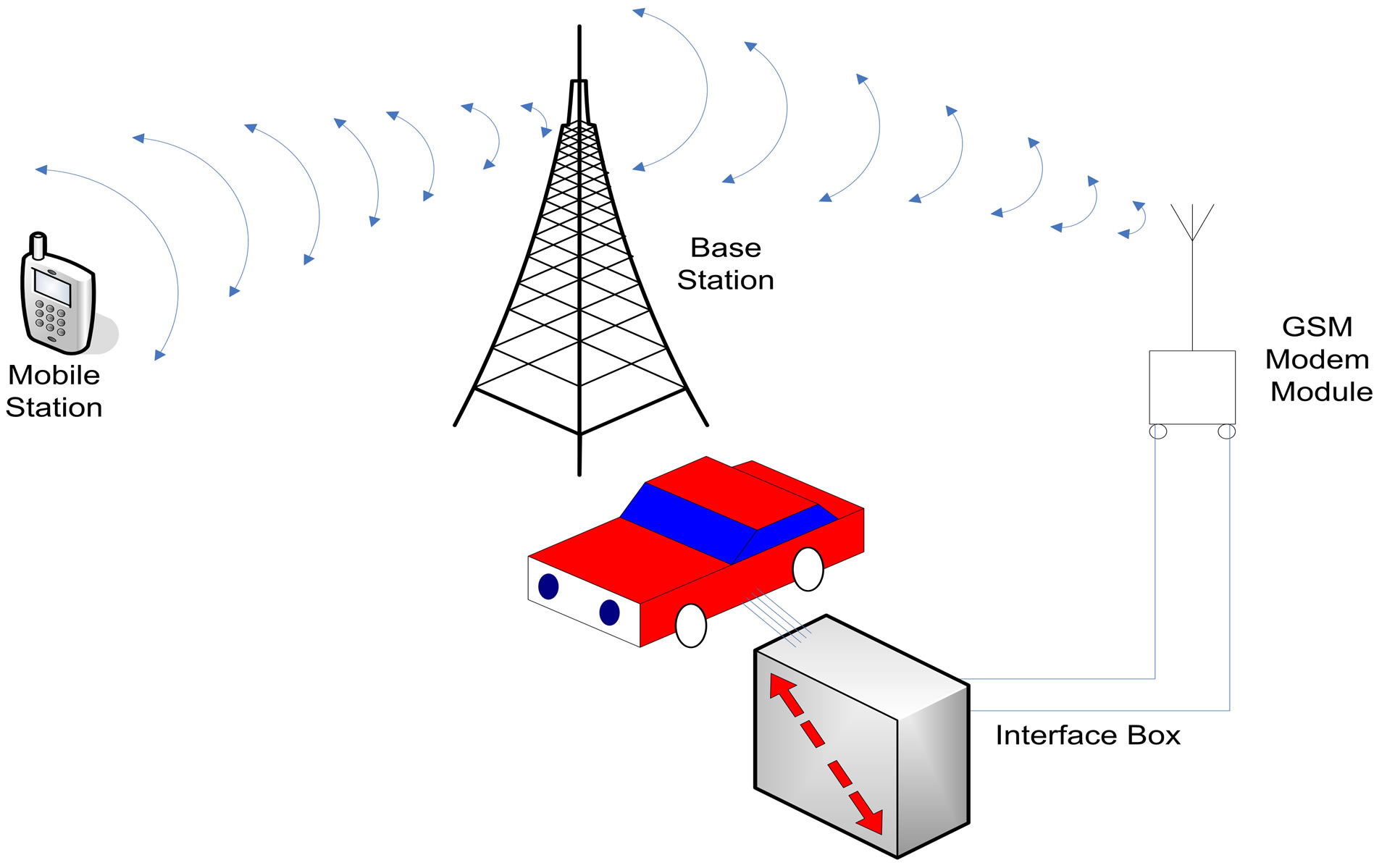
Figure 1. Block diagram of a remotely controlled vehicle anti-theft system via GSM network.
the modem is properly connected, some “AT” commands were sent to the modem from the write window of HyperTerminal. The command response from the modem indicates ERROR, OK or other possible responses (JS, 2004) [1]. If the modem fails to communicate, the fault diagnostics routine can be referred to (Comtech, 2005) [3].
2.1. Interacting with the GSM/GPRS Modem Module
This segment handles the data communication with the GSM/GPRS modem module. Communication with the module is via the communication (serial) port of a PC. In order to program the GSM/GPRS modem module for this project application, a serial connection was established with the modem.
2.2. GSM/GPRS Modem Module Connector Consideration
The connector headers listed in Table 1 describes the functional units located on the modem module (Comtech, 2006) [4]. The connector layout is as shown in Figure 3.
However, out of the list only CON 1, CON 2 and CON 4 is applicable to this project.
2.3. Hardware Interfacing Vehicle Sub-Systems with GSM/GPRS Modem Module
This section describes how various application units are interface with the GSM/GPRS modem. The GSM/GPRS modem however serves as the central controlling unit. This was made possible by the presence of I/O lines on the modem which eliminates the need for a microcontroller unit.
2.3.1. Vehcile Demobilizer Sub-System
An I/O line on the modem controls the vehicle demobilizer unit. This line energizes a relay which cuts of bat-
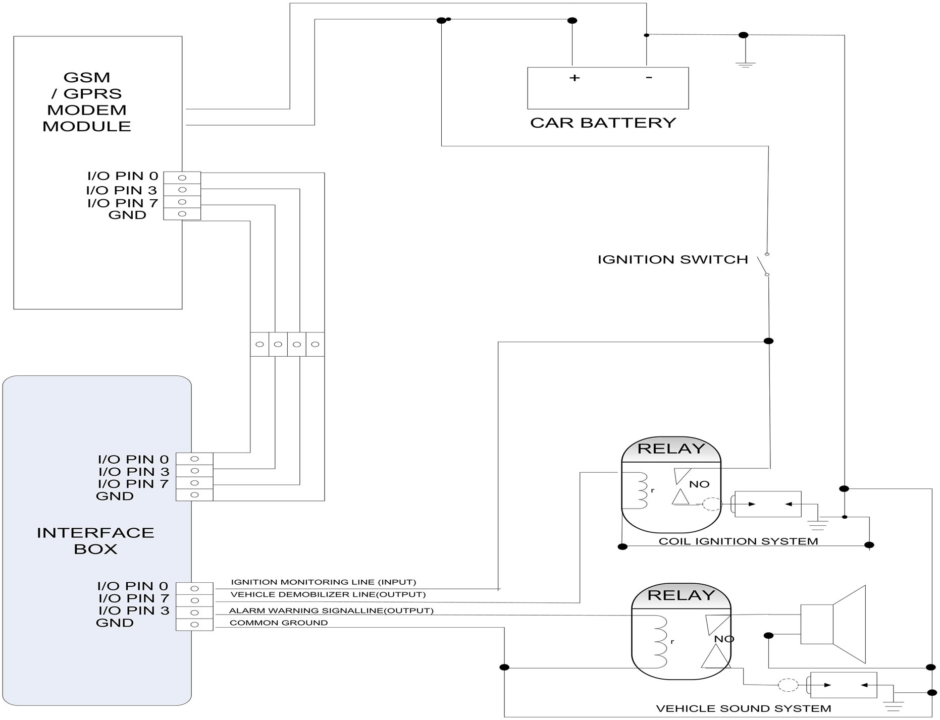
Figure 2. Wiring diagram of vehicle control subsystem.
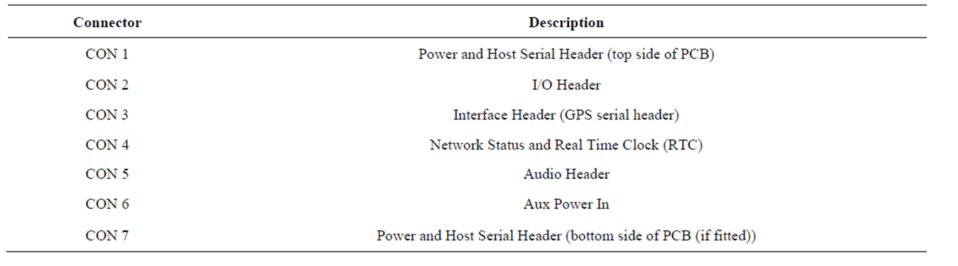
Table 1. GSM/GPRS modem module connector description [4].
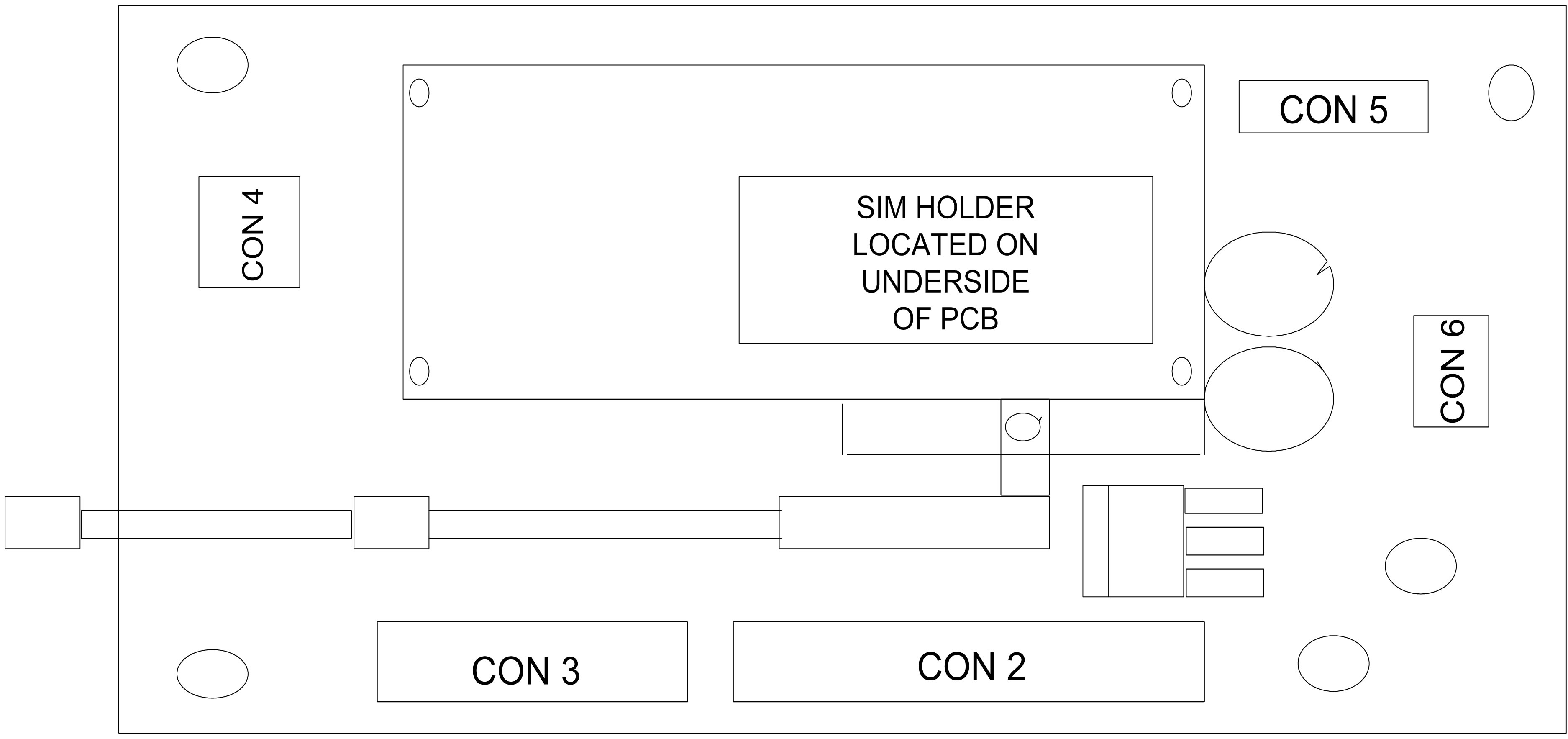
Figure 3. GSM/GPRS modem connector layout [4].
tery supply to the coil ignition system of the vehicle. The circuit schematic for the section is as shown in Figure 4.
2.3.2. Remote Ignition Monitoring System
This section is made up of a unit that monitors the status of the vehicle ignition unit. In this case an I/O line is configured as an input to the modem. The signal received at this I/O line is used to trigger the modem to wakeup up from a sleep mode. After which it sends an emergency warning signal by auto-dialing the user’s mobile phone number. The interfacing diagram is as shown in Figure 5.
3. Mode of Operation
As mentioned in the earlier the mobile system is an integration of sub-systems. The mode of operation of each of these sub-systems and their subsequent integration are critically and fully explained in the below.
3.1. Remote Access Link
This segment deals with the means by which the user gains access to the vehicle subsystems. The link is via GSM network. A GSM Modem Module mounted inside the vehicle provides the facility to be able to communicate with the mobile station (mobile phone or any other GSM modem device).Various range of GSM/GPRS modem module exist with various range/mode of operating frequency. Also the GSM/GPRS modem module can be configured to accept instructions only from specified mobile phone numbers.
A SIM card reader/slot contained in the board houses the SIM card used in this application. Once the user dials the number residing in the module SIM card the GSM/ GPRS modem module respond and connection is established between the access remote link and the vehicle sub system.
After this link has been established then necessary control and monitoring actions can be initiated on the mobile station (mobile phone) and this will allow the owner of the vehicle to initiate necessary command programs (AT commands) and carry out the desired actions depending on the security status of the vehicle at that particular time.
The whole segment integrates various sub-systems for proper operation this are; GSM Modem Module, Mobile station (mobile phone) and the base station.
The system was designed so that text messages sent from a remote location using a mobile phone are transmitted to the GSM modem which interprets the message and in turns encodes and performs the action specified in a command line via the communication I/O port [3].
3.2. GSM Modem Module
Modem module GSM/GPRS integrated wireless modems provide a quick and easy way to insert GSM and GPRS functionality into systems and terminals. Available in dual-band configurations, this modem constitutes a selfcontained, fully integrated implementation of the GSM/ GPRS Standard. It has an integrated SIM connector.
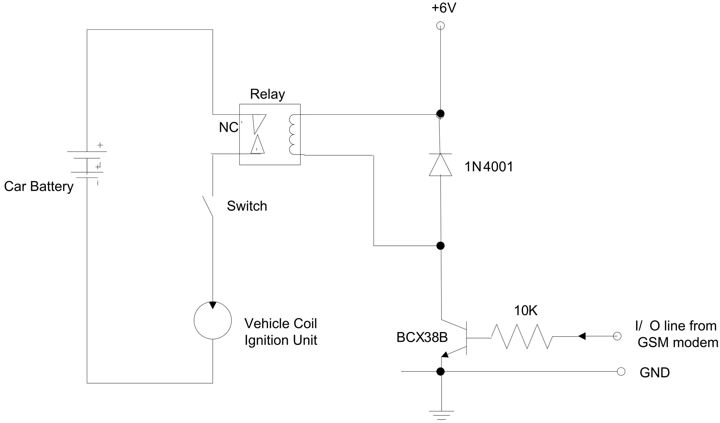
Figure 4. Demobilizer interfacing circuit.

Figure 5. Ignition monitoring interfacing circuit.
The modem module has two logical functional points, the hardware port and the software port (AT commands) [3].
3.2.1. Hardware Consideration
The GSM modem module used is based on a dual band RF Module, which is it can operates on both frequency of 900 MHZ and 1800 MHZ with SMS (short message service) service. It has an integrated SIM socket which houses the SIM and operates on the baud rate of 9600 baud, on the 10-pin TTL (RS232 optional) serial host interface at the point of connection to other networks/ computer peripherals [3,4] as shown in the Figure 6.
3.2.2. Software Consideration (AT Commands)
The software used in programming the GSM MODEM MODULE is a set of AT commands. AT commands are at the soul of all Modems , the GSM modem inclusive It is important to note that there are general AT commands and proprietary commands are broad-specific. However, the software used to pre-configure the GSM Modem Module is the automated mode firmware before the introduction of the AT Commands [6].
3.3. Mobile Station (Mobile Phone)
The Mobile station acts as a remote control device which grants the owner of the vehicle the access to the vehicle from any part of the world with GSM coverage. The SMS feature provided by GSM was employed by the design predefined to text messages from the mobile phone to the GSM was employed by the design to text predefined messages from the mobile phone to the GSM modem .Since it is an I/O device, it displays acknowledgements received from the home automation segment [7].
3.4. Base Station
This serves as an interface between the mobile phone and the GSM Modem Module. The base station is responsible for receiving data, at 9600 bps through the antenna of the GSM Modem Module which in turn decode the message on reception and performs the automated actions as indicated by the content of the message and the acknowledgement of reception is sent back to the mobile phone through the same coding and decoding process via the base station.
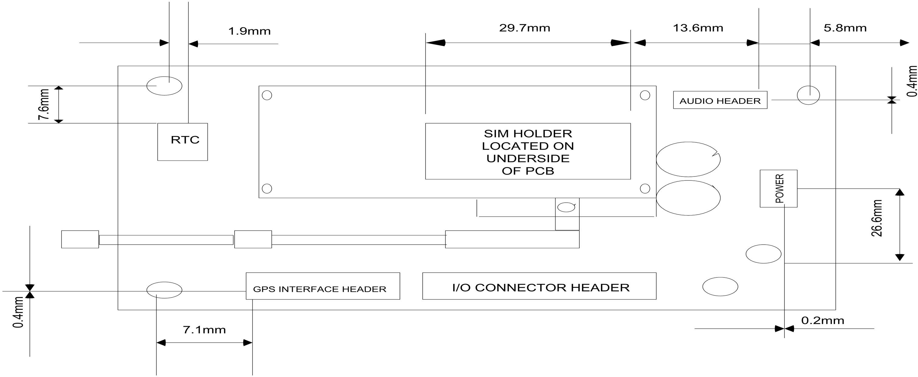
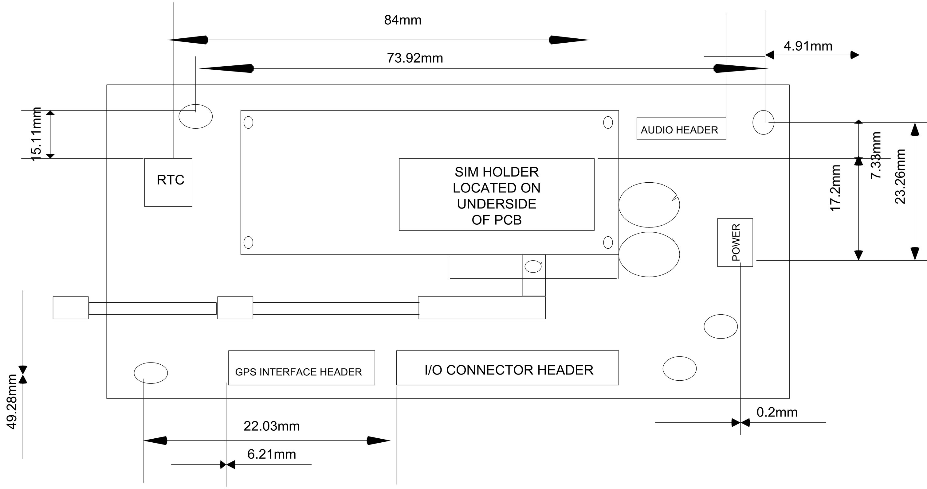
Figure 6. Plan view of the GSM/GPRS modem board [5].
3.5. Vehicle Subsystems
This segment handles the various actions which the user wishes to perform once connection is established between the mobile station and the vehicle GSM/GPRS modem module. The vehicle subsystems are as follows;
• Vehicle Demobilizer System
• Remote emergency warning system.
3.5.1. Vehicle Demobilizer
This system automatically cuts off the battery supply to the ignition system of the vehicle. An I/O pin in the GSM/GPRS Modem Module is used to control this action.
The basic components of the ignition system are the ignition coil, high voltage ignition wire, the distributor and spark plugs.
The automotive ignition system has two basic functions; it must control the spark and timing of the spark plug hiring to match varying engine requirement; and it must increase battery voltage to a point where it will overcome the resistance offered by the spark plug.
The battery is the source of the voltage for the spark that is used to ignite the mixture of the proper microsecond in the cylinder. The spark requires thousands of volts to occur as much as 120,000 volts. However, the ignition coil is the source of the high voltage that is used. The coil is a simple transformer then steps up battery voltage to the thousands of volts the spark plugs need. The coil has two sides, there is the 12 volt or primary side; this side has a few hundred turns of a large diameter wire and builds up the magnetic field in the coils. The other side is the high voltage or secondary side. The side has thousands of turns of smaller diameter wire. The coil uses “electromagnetic induction” to create the high voltage.
When the voltage on the primary side is turned off, the collapsing magnetic field induces a voltage in the secondary side producing the thousands of volts the spark plugs need.
The distributor is the controlling element of the system it switches the primary current to the proper spark plug each time a spark is needed. The distributor is a stationary housing surrounding a rotating shaft. The shaft is driven at one-half engine speed by the engine’s camshaft through the distributor drive gears. A cam operates the contact points, which are mounted on a plate within the distributor housing. A rotor is attached to the top of the distribution shaft The outer end of the rotor passes very close to the contacts connected to the spark plug leads around the outside of the distributor cap.
The current from the coil secondary windings flows through the coil high-tension lead to the center of the distributor cap, where it is distributed by the rotor to one of the outer terminals in the cap.
From there, it flows through the spark plug lead to the spark plug. This process occurs in a split of seconds and is repeated every time the points open and close, which is up to 1500 times a minute in a 4-cylinder engine at idle.
For the ignition system (as shown in Figure 7) to perform the function of demobilization of the vehicle the normally closed relay connected between the positive terminal of the battery and the coil of the ignition becomes normally open upon reception of command lines from the mobile phone via the signal received by the modem module.
3.5.2. Remote Emergency Warning System
This system deals with the means by with the user keeps track of the status of the vehicle at every instance. In this system, the Input/output line on the GSM/GPRS modem

Figure 7. Coil ignition systems.
module is configured as an input pin and to accept emergency electrical when the vehicle ignition is turned on.
The modem is configured to continuously monitor the status of the pin. Once an incoming electrical voltage is detected on the corresponding input, an originally configured SMS message is sent to the pre-configured mobile phone number. This indicates that the vehicle is on.
However, this system is expected to operate any time the ignition system is on. But in order to prevent frequent occurrence of this warning signal any time the ignition turned on, then the authorized user has to initiate some control actions on the system.
4. Conclusions
The major aim of this project was to design and construct a remotely controlled vehicle anti-theft system via GSM network. Which can be accessed from a remote/distant location where there is GSM coverage? And the aim was also to monitor, control and initiate the vehicle demobilize when the vehicle has been stolen [9,10].
The GSM modem module for the remote communication was gotten from Comtech holdings limited Bolton United Kingdom (UK). This GSM modem module incorporates on it, a micro-controlling unit which was programmed to control and monitor the vehicle subsystems.
However, a toy car was used as a prototype display of this project work. The toy-car was configured to send a warning message to the user on the press of the start button. Also, the prototype car was immobilized and demobilized from a mobile phone via SMS.
Aside from the drawback of inconsistence in the availability of GSM network in the country, the project will be about a revolutionary improvement in the defense and security sector of the country.
Recommendation
Remotely controlled vehicle anti-theft system via GSM network is highly recommended if cost effectiveness, resource management and the life of the owner are of great priority. Having in mind that it reduces harm to the vehicle owners and it enables easy recovery of the stolen vehicle by security agents/operatives [8].
REFERENCES
- National Motor Vehicle Theft Reduction Council, 2007.
- Freepatentsonline, 2004-2007. http://freepatentsonline.com/2004188164.html
- Comtech Holdings Ltd., “Uweblite GSM/GPRS Getting Started Guide,” 2005.
- Comtech Holdings Ltd., “JS Uweblite Design Manual,” 2004.
- Comtech Holdings Ltd., “Uweblite Design Manual,” 2006.
- Comtech Holdings Ltd., “UWeb/UWeBox Lite GSM/ GPRS AT Commands Manual Guide,” 2004.
- E. A. Aderibigbe, “Design and Construction of a Home Automation via Domestic Power Line and GSM Network,” Unpublished B.Tech Thesis, Ladoke Akintola University of Technology, Ogbomosho, 2005.
- A. A. Raheem, “Project Methodology (A Practical Guide),” Emola-Jay Communications Incorporated, Ibadan, 2003.
- S. Amos, et al. “Design of a GSM Cell-Phone Based Vehicle Monitoring and Theft Security System,” International Journal of Electrical and Electronics Engineering (IJEEE), Vol. 1, No. 3, 2012, p. 101.
- U. Valentine, “Design of GSM Based Remote Control System,” 2012. http://hyattractions.wordpress.com/2012/08/24/design-of-gsm-based-remote-control-system/