Wireless Sensor Network
Vol.5 No.6(2013), Article ID:33338,6 pages DOI:10.4236/wsn.2013.56015
Energy Saving in WSN with Directed Connectivity
1A. G. College, Pune, India
2Department of Electronic Science, University of Pune, Pune, India
Email: neha.d68@gmail.com
Copyright © 2013 Neha Deshpande, Arvind Shaligram. This is an open access article distributed under the Creative Commons Attribution License, which permits unrestricted use, distribution, and reproduction in any medium, provided the original work is properly cited.
Received April 27, 2013; revised May 26, 2013; accepted June 9, 2013
Keywords: Directed Coverage; Food Grain Warehouse (FGW); Directional Antenna; Deterministic Deployment; Energy Advantage; QoS; Redundancy
ABSTRACT
Wireless Sensor Networks have been implemented in many indoor applications such as offices, hospitals, laboratories for monitoring the parameters such as temperature, humidity etc. Most of the applications have used omnidirectional antennas. In randomly deployed ad hoc wireless sensor networks, this may be useful to achieve coverage and connectivity with unknown neighbors. In case of deterministic deployments such as in case of food grain storages where locations of the sensor nodes are mostly fixed, the main challenges are unstable and vacillating conditions in the godowns during loading and unloading of sacs as well as unpredictable changes in climate. Most of the commercial motes generally use omnidirectional antennas. Energy overheads increase considerably with omnidirectional antennas. Directivity increases energy saving but may be at the cost of redundancy. This paper is mainly focused on the energy advantage in ad hoc wireless sensor networks deployed in large food grain storages and energy overheads required for obtaining certain level of redundancy using directional antennas. Finally, we conclude that energy advantage can be achieved even if we overcome redundancy to certain extent.
1. Introduction
Indoor RF propagation is not the same as it is outdoors. This is due to the presence of solid obstructions, ceilings, and floors that contribute to attenuation and multipath signal losses.
Indoor environment can also be classified as near line of sight (LOS) and non LOS. In near LOS environments, where you can see the base station or the routers such as in the hallways, multipath is usually minor and can be overcome easily. The amplitudes of the echoed signals are much smaller than the primary one. However, in non LOS conditions, the echoed signals can have higher power levels, because the primary signal might be partially or totally obstructed, and generally more multipath is present. Shorter wavelengths have more probability to get absorbed and distorted by a building material [1]. In large indoor environments, if the wireless sensor network is deployed, such energy losses are obvious. If we increase the power of individual nodes to achieve more coverage, we end up with coverage at the cost of large energy overheads.
There are several surveys providing with in-depth background research on sensor networks [2-5]. Typically, sensor nodes avoid long distance communication with the base station directly. Instead the nodes use multihop communications to improve network lifetime, a lot of research have been done on designing the energy efficient MAC protocols [6-8]. Directional antennas have been used to improve throughput and delay in WSN [9]. Directional antennas provide angle-of-arrival information, which can be used for localization and routing algorithms in wireless sensor networks. Different designs of antennas have been tried to increase the communication range and reduce the number of hops [10]. The directional antenna patterns have been checked for various models where sensing range and communication range may vary randomly [11]. Connected coverage with sensitivity consideration approach is discussed by S. H. Khasteh et al. [12].
The large food grain warehouses are special case for WSN in indoor environment application. The warehouses are distributed over the area of few acres. The activity inside each godown is monitored by an ad hoc wireless sensor network that reads the parameters such as temperature, humidity, carbon dioxide levels etc. after fixed time intervals. Also being increasingly demanded are rigorous inspections, and systematic detection and recording of quality and safety parameters. After producing huge quantities of food grains, as is the case with Indian Agriculture, the next challenge is to provide an effective, safe and viable storage method. We need to protect these food grains from problems such as unpredictable weather conditions, high humidity and weeds growth [13]. The battery operated nodes are connected as multihop ad hoc networks. This network may suffer from loss of connectivity due to several reasons such as battery life, broken linkages, attenuation due to obstacles. There may be some acute places where it is not possible to achieve connectivity and hence coverage [14].
The energy overheads can be reduced significantly by use of larger number of nodes with small range which ultimately require less power as well as improve information resolution. Using these nodes multihop communication can be established achieving reduction in energy overheads.
In this paper, we have discussed the issues related to the sensor deployment along with the directivity of antenna for maximum coverage in the large food grain warehouse. Energy overheads due to node with large communication range and to achieve reduction in energy overheads with multihop communication using nodes with less power are calculated. Energy overheads required for obtaining certain level of redundancy with directed coverage is discussed.
2. Theoretical Considerations
Omnidirectional antennas provide a 360 degree horizontal radiation pattern. These are used when coverage is required in all directions (horizontally) from the antenna with varying degrees of vertical coverage. Polarization is the physical orientation of the element on the antenna that actually emits the RF energy. An omnidirectional antenna, for example, is usually a vertical polarized antenna. Directional antennas focus the RF energy in a particular direction. As the gain of a directional antenna increases, the coverage distance increases, but the effective coverage angle decreases. For directional antennas, the lobes are pushed in a certain direction and little energy is there on the back side of the antenna. Directivity (D) is the ratio of the radiation intensity in a given direction from the antenna to the radiation intensity averaged over all directions.
If directional antenna is used, the radiation intensity of a major lobe of many antennas can be adequately represented by Equation (1)
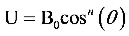 (1)
(1)
where B0 is the maximum radiation intensity. The radiation intensity exists only in the upper hemisphere (0 ≤ θ
≤  , 0 ≤ φ ≤ 2) as shown in Figure 1.
The half power point of the pattern occurs at θ = 60˚ and beam width in the direction of θ is 120˚. The pattern is independent of φ direction coordinate and the beam width in the other plane is also equal to  .
.
The beam solid angle 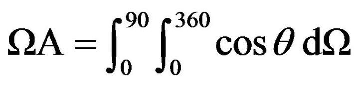
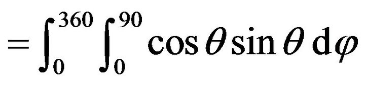 (2)
(2)
= п steradians.
The directivity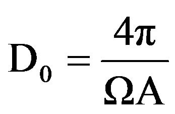 .
.
And in terms of effective antenna aperture.
Ae, power density of plane wave incident on antenna, S and wavelength λ, we can express the power delivered by antenna to receiver as
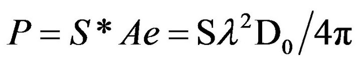 . (3)
. (3)
The Equation (3) shows that power received is directly proportional to the directivity of the antenna. Figure 2 shows the directivity patterns of various directional antennas and omnidirectional antenna. The power required for omnidirectional antenna is more as it radiates in all directions. As the directivity increases, it is observed that the range increases.The values of directivity of various antenna types [1] is given in Table 1.
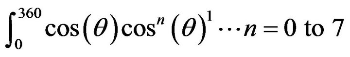
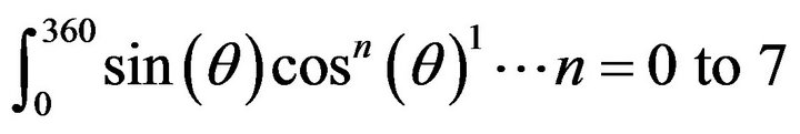
Using Equations (1)-(3) power is calculated for different values of n. and fractional energy saving is calculated using Equation (4) and plotted as shown in Figure 3.
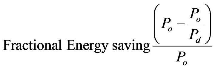 (4)
(4)
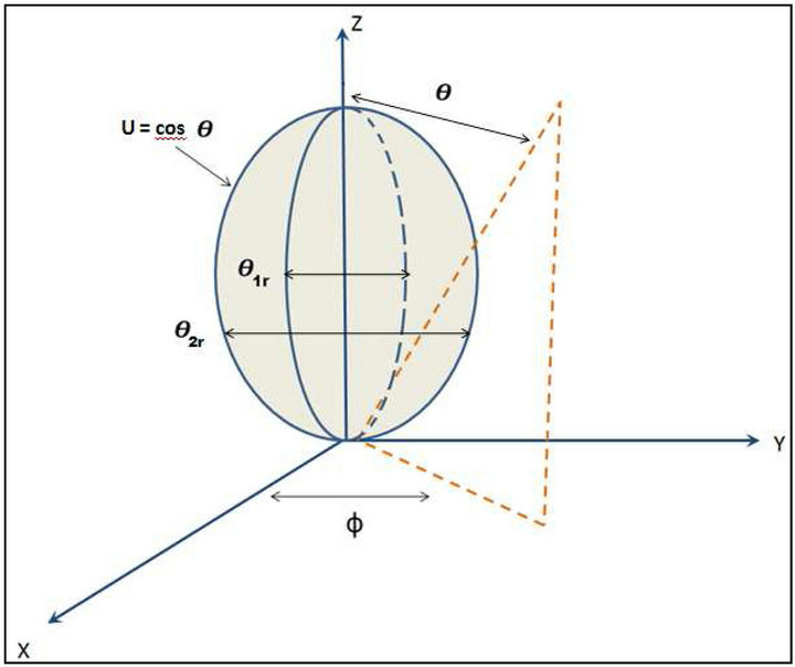
Figure 1. Radiation intensity of a major lobe of directed antenna.
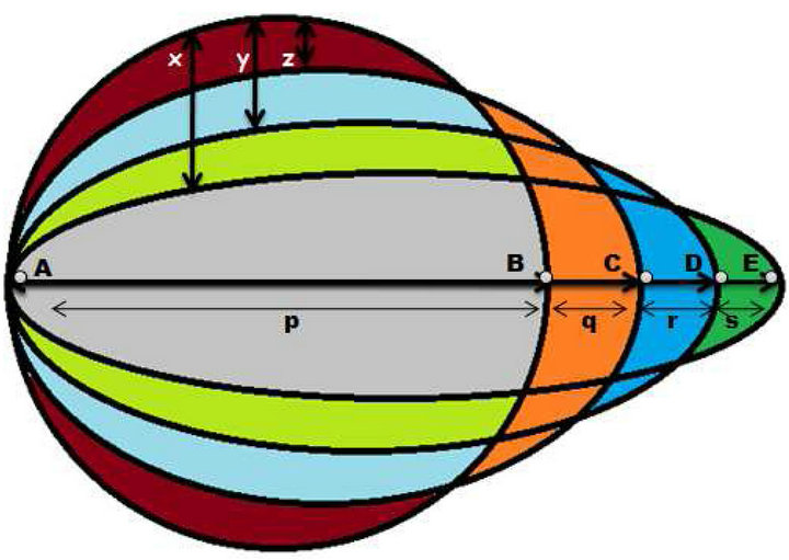
Figure 2. Comparison of directivity patterns directed antennas with omnidirectional antenna.
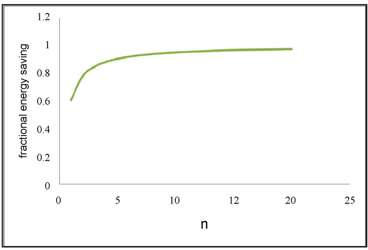
Figure 3. Fractional energy saving with directed coverage.
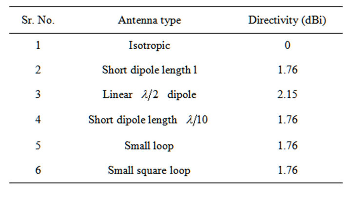
Table 1. Directivity of various antennas.
where Po is Power radiated by omnidirectional antenna and Pd is the power radiated by directional antenna.
In practice the commercially available WSN nodes use different types of antennas. These are summarized in the Table 2. The antennas used are mostly omnidirectional as the nodes are designed for general applications.
Thus it is seen that use of directional antennas could lead to energy saving in principle. Following section presents the results and discussions on systematically carried out study in this direction.
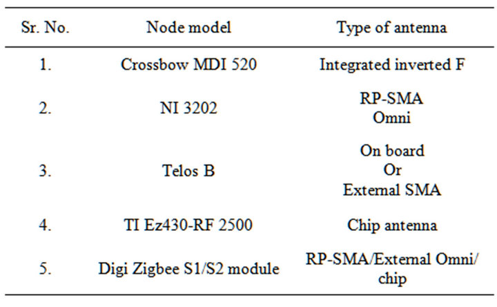
Table 2. Antennas of various commercially available WSN nodes.
3. Results and Discussions
3.1. Calculation of Energy Overheads and Their Dependence on Multihop
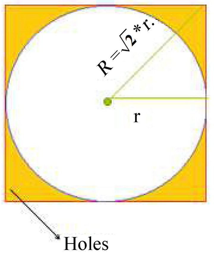
Calculation of energy overheads due to node with large communication range and to achieve reduction in energy overheads with multihop communication using nodes with less power is discussed in this section [14]. Consider a case where a single node is placed in the center of the area under consideration. There are two possibilities; one is the circular area inside the square where the range of the node is
 (5)
(5)
The other possibility is the range is R = 2*r. (6)
Figure 4 shows both the possibilities. In first case as shown in the figure, the area at the corners shown with red shading is not covered and leads to the holes. Now if we increase the range, at one point complete area is covered but the remaining part is just the unwanted coverage as shown with green shading in figure.
The area of the inner circle
 . (7)
. (7)
The area of the outer circle 
 . (8)
. (8)
The area of the square
 . (9)
. (9)
Using (3) and (5), area of the region of holes is
 . (10)
Using Equations (8) and (9) area of the outer unused region is
 . (11)
If r = 4 units, we get from Equation (8)A = 9.76 unit2. (12)
And from (9)A’ = 36.4. (13)
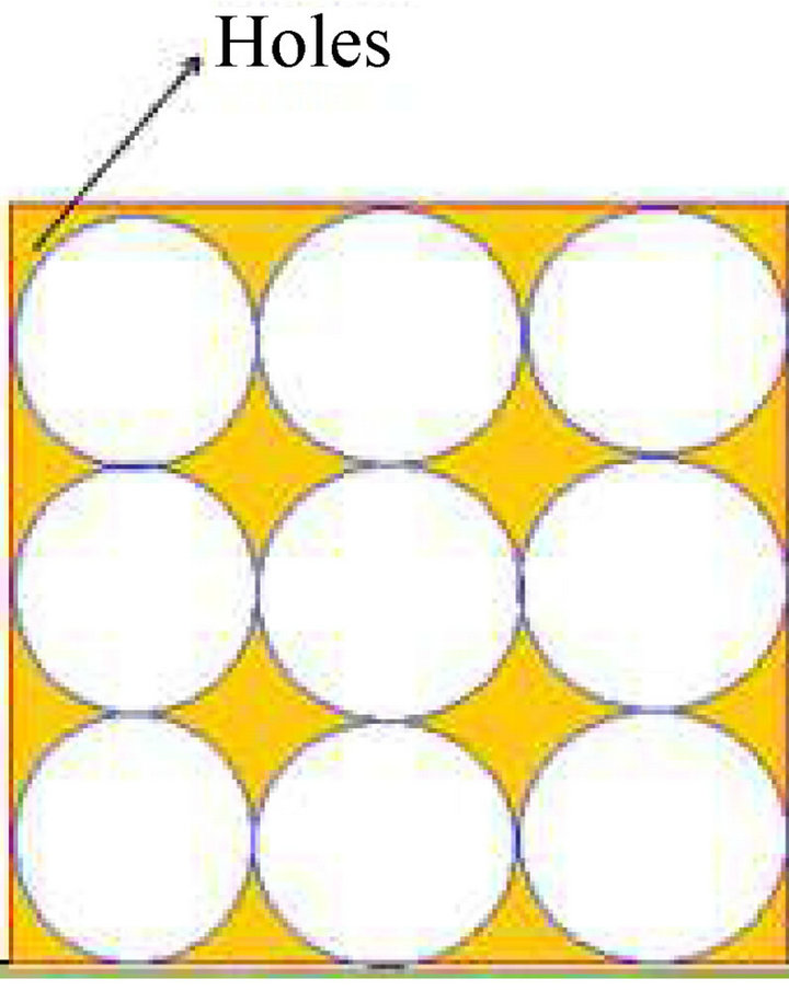
Thus to overcome the holes, the overheads are 4 times. Instead of deploying a node with large power, if we deploy nodes with less power and arrange them as shown in the Figure 5, we can clearly see that the range and hence the power is less and hence we can achieve minimization of energy utilization in the network. The area covered without overlap can be calculated as  n such sensor nodes are to be placed in a large warehouse with deterministic deployment techniques, using more number of low power nodes with ad hoc network arrangement. This will save energy overheads and still provide sufficient coverage. This type of communication will utilize maximum energy and directivity will be zero. In case of a food grain warehouse if we deploy such isotropic node in the corner where it is required to get critical data about seepage of water if any near the grain stacks where absorption of the signal will be high and communication may not be required in the other direction.
3.2. Energy Advantage with Directional Antennas
Now next step is to calculate actual energy advantage using practically available directional antennas. The power required is calculated using Equations (14) and (15). Energy advantage is calculated by further comparing it with the power required for the same distance connectivity using isotropic antenna. Power required is calculated by calculating the area covered by the directed beam of the antenna.
 (14)
(14)
and
 . (15)
The outer most plot in Figure 6 shows the coverage obtained using omnidirectional antenna. The directivity goes on increasing and the energy is saved. The energy advantage increases with the increasing directivity as shown in Figure 7.
The isotropic antenna has directivity 1 and radiates energy to all directions. When we consider the scenario shown in Figure 2, isotropic antenna requires certain amount of power to achieve communication between point A and B. With directive antenna, this power will go on increasing and the minimum amount of power to achieve communication between A and B will go on decreasing. The % energy advantage with directivity is clearly observed in Figure 6. It is observed from Figure
 (a)
(a)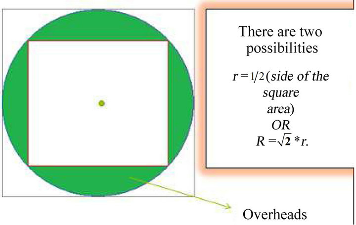 (b)
(b)
Figure 4. Coverage with one node: 4(a) shows holes when communication range power is 2*r and 4(b) shows nodes with .
.
 (a)
(a)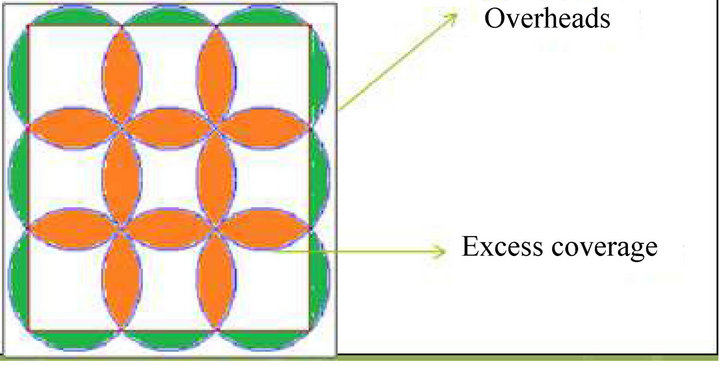 (b)
(b)
Figure 5. Coverage with 9 nodes. 5(a) shows coverage with multihop small nodes 5(b) shows provision for redundancy.
6 that the use of directional antenna is always advantageous in terms of energy saving. But as the directivity increases, the redundancy is lost.

Figure 6. Directivity of different antenna.
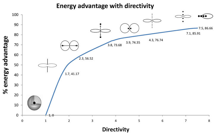
Figure 7. % energy advantage vs directivity.
3.3. Energy Overheads to Achieve Redundancy
Now if the node under consideration fails, then connectivity is completely lost. If we try to achieve connectivity with redundant nodes located at adjacent positions, we have to increase the power. This concept is explained in Figure 8.
The nodes “b” to “I” are placed at different positions. The antenna corresponding to the inner lobe covers certain area and if the node is placed above that boundary, then we have to increase the power so as to achieve that coverage. Node “b” is covered by the inner lobe but if we need redundancy so as to achieve coverage of node “c” as well then we have to increase the power by certain amount. This is an energy overhead for that antenna. Similarly we can consider for coverage of nodes c, d, e, f, g, h or i at different heights. The amount of overhead will increase as we go on increasing the distance of the node from the reference position with respect to the antenna under consideration. Figure 9 shows the energy overheads due to change in the location of the nodes.
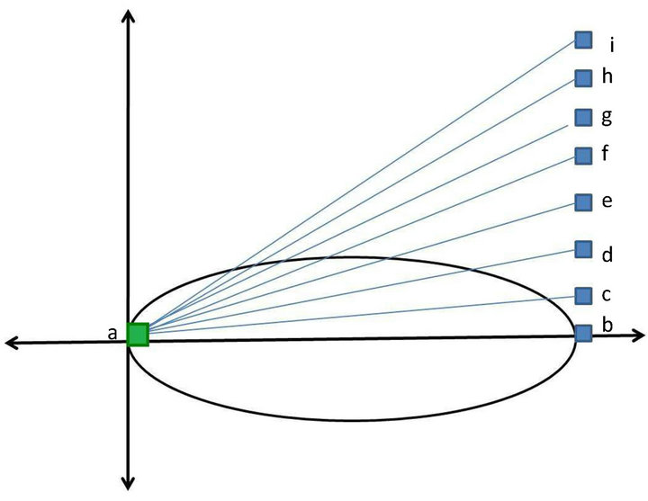
Figure 8. Redundant nodes at adjacent locations.
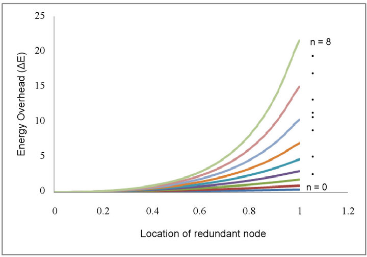
Figure 9. Energy overheads with change in node locations.
When the directional antenna is used, energy can be saved but while addressing the redundancy issue it is disadvantageous. More over we have to increase the power of the antenna so as to achieve reduandancy up to certain level. The amount of power required to achieve redundancy upto say node “e” with the maximum directional antenna is still less than the amount of power utilized by the omnidirectional antenna Thus we can conclude that directional antennas offer energy advantage over omnidirectional antenna depending upon the amount of reduandancy required by the application.
3.4. Directional Antennas in Food Grain Warehouse
In case of directional antennas placed in the large food grain warehouse, depending upon the three different possibilities of base station positions are considered in this set up. In such scenarios, if omnidirectional antennas are placed, at all locations, it will transmit the power in all directions and hence energy radiated near walls will be wasted. In the matrix of Figure 10 the upper row shows
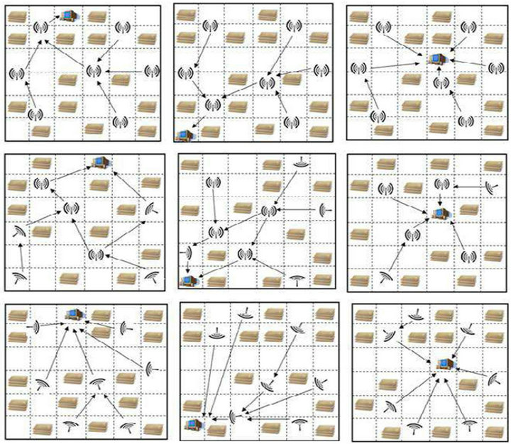
Figure 10. FGW with various arrangements of base station and combinations of antenna.
case 1 where such deployment is demonstrated. In second case, the FGW with the same arrangement but omnidirectional antennas in the middle sections and directional antennas near the walls can save excess energy wasted towards the walls. This arrangement has advantage of flexibility. The interior can be covered and redundancy can be achieved with the omnidirectional antennas. The third row is special case where in all directional antennas are used. This arrangement has advantage of considerable energy saving but that at the cost of flexibility.
REFERENCES
- J. D. Kraus and R. J. Marhefka, “Antennas for All Applications,” 3rd Edition, McGraw-Hill Publication, Boston, 2008.
- S. S. Iyengar, L. Prasad and H. Min, “Advances in Distributed Sensor Integration: Application and Theory,” Prentice-Hall, Upper Saddle River, 1995.
- I. F. Akyildiz, W. Su, Y. S. Subramaniam and E. Cayirci, “Wireless Sensor Networks: A Survey,” Computer Networks, 2002, Vol. 38, No. 4, pp. 393-422. doi:10.1016/S1389-1286(01)00302-4
- D. Ganesan, R. Govindan, S. Shenker and D. Estrin, “Wireless Sensor Networks,” ACM Mobile Computing and Communications Review, Vol. 5, No. 4, 2001, pp. 11-25.
- M. Miller and N. Vaidya, “A MAC Protocol to Reduce Sensor Network Energy Consumption Using a Wake up Radio,” IEEE Transaction on Mobile Computing, Vol. 4, No. 3, 2005 pp. 228-242. doi:10.1109/TMC.2005.31
- W. Ye, J. Heidermann and D. Estrin, “Medium Access Control with Coordinated Adaptive Sleeping for Wireless Sensor Networks,” IEEE/ACM Transactions on networking, Vol. 12, 2004, pp. 493-506.
- J. Polastre, J. Hill and D. Culler, “An Adaptive Energy Efficient MAC Protocol for Wireless Sensor Networks,” SenSys ‘04 Proceedings of the 2nd International Conference on Embedded Networked Sensor Systems, 2004, pp. 95-107. doi:10.1145/1031495.1031508
- H.-N. Dai, “Throughput and Delay in WSN using Directional Antennas,” IEEE, ISSNP, 2009.
- M. Nilsson, “Directional Antennas for Wireless Sensor Networks,” 9th Scandinavian Workshop on Wireless Adhoc Networks (Adhoc’09), Uppsala, 4-5 May 2009.
- Z. M. Yu, et al., “Connected coverage in Wireless Sensor Networks with Directional Antennas,” INFOCOM, IEEE, 2011, pp. 2264-2272.
- S. H. Khasteh, S. B. Shouraki, N. Hajiabdorahim and E. Dadashnialehi, “A New Approach for Integrated Coverage and Connectivity in Wireless Sensor Networks,” Computer Communications, Vol. 36, No. 1, 2012, pp. 113-120.
- Reference Document, “Role of Moisture, Temperature and Humidity in Safe Storage of Food Grains,” IGMRI, Hapur, 1996.
- C. A. Balanis, “Antenna Theory,” 3rd Edition, 2005.
- D. Neha and A. D. Shaligram, “Minimization of Energy Overheads in Ad Hoc WSN Deployed in Food Grain Warehouse,” Proceedings of NCRIGE-2013, pp. 361-364.