Wireless Sensor Network
Vol. 1 No. 2 (2009) , Article ID: 519 , 7 pages DOI:10.4236/wsn.2009.12010
The Application of Optical CDMA-Based Fiber Radio Networks in Wireless Sensor Networks
Department of Electronic Engineering, Kun Shan University, Tainan, Taiwan, China
Email: ccyang@mail.ksu.edu.tw
Received April 29, 2009; revised May 8, 2009; accepted May 9, 2009
Keywords: Optical Code-Division Multiple-Access (OCDMA), Passive Optical Network (PON), Arrayed Waveguide Grating (AWG), Prime Code
ABSTRACT
One fiber radio scheme using shifted prime codes for interference elimination is proposed for optical code-division multiple-access (OCDMA) network. By taking advantage of the cyclic property of the shifted prime codes in the same code groups, the proposed compact decoder is low cost and suitable to be used in the task manager node in the applications of wireless sensor networks. The performance comparison for several OCDMA-based fiber radio networks is also given to clarify the advantage of the proposed one.
1. Introduction
In today’s mobile radio networks, the provision of broadband services between a large number of remote base stations (RBSs) is required. To develop simple and low-cost RBSs for high rate transmission, the combination of mobile radio and optical fiber network is one possible solution since the components for complicated operation of signal processing can be moved to control base station (CBS) [1]. In the case of wireless sensor networks (WSNs) nowadays, the condition may be similar [2]. The sensor nodes need to route the collected data back to the sinks, and the sinks may communicate with the task manager node via networks for long distance transmission. Therefore, fiber radio networks can also provide the communication between the sinks (e.g. RBS) and the task manager node (e.g. CBS) to simplify the design of the sinks.
Code division multiple access (CDMA) techniques were investigated for optical network applications during the last 20 to 25 years. These techniques allow many users to access the common channel asynchronously and securely, and, since dedicated time or wavelength slots do not have to be allocated, high statistical multiplexing gain can be offered even in bursty traffic. These characteristics distinguish CDMA from other multiplexing schemes such as time division multiple access (TDMA) and wavelength division multiple access (WDMA). Several OCDMA-based fiber radio schemes were proposed [3-6]. Among these, fiber radio schemes based on spectral-amplitude-coding (SAC) had the advantages of multiple access interference (MAI) elimination and the avoidance of sampling before the optical encoding process [4-6].
A code that can be used in the SAC scheme is denoted as (N, w, λ), where N is code length, w is code weight, and λ is the in-phase cross correlation [6]. Originally unipolar m-sequences were used in the SAC-based networks [7], and, to enhance the network performance, code sequences with complementary code keying ability such as Hadamard codes [7] could be used. However, since these two code families had code weights equivalent to half of the corresponding codelengths, they induced serious phase-induced intensity noise (PIIN) in the photodiodes of the decoders. To suppress the phase-induced intensity noise in the photodiodes of the decoders, several codes with ideal λ ( λ = 1) were proposed, such as Balanced Incomplete Block Design (BIBD) codes [8]. The former had fully cyclic property and N × N arrayed waveguide grating (AWG) can be used as compact coding devices [9,10]. However, when the total number of users in the network increased, a large number of AWG ports were required and the effect of crosstalk was more serious.
To enlarge the network capacity further, new coding schemes using codewords with small λ and having the two-code keying ability can be developed. In [11], one coding scheme was proposed and code sequences with λ=0 or 1 can be used for two-code keying of information bits. By the use of the cyclic property for shifted prime (SP) codes, compact encoder structure based on cascaded AWGs and simplified decoder based on fiber Bragg grating (FBG) were also proposed for the application of passive optical networks (PONs). The optical line terminal (OLT) encoder based on cascaded AWGs had the advantage that only p×p and 1×p AWGs were needed in the encoder for SP codes with codelength p2.
In this paper, the application of SAC schemes using SP codes in radio fiber network is explored. By the modification of the encoder/decoder pair for the downstream transmission in the PON in [11], the encoder/decoder implementation in the upstream transmission (from RBSs to CBS) for the fiber radio network can be obtained. Performance analysis takes thermal noise and PIIN into account. It shows that, as compared to several fiber radio schemes based merely on SAC, the use of SP codes allows larger number of RBSs to access the network simultaneously under a given carrier-to-noise ratio (CNR).
2. Fiber Radio Network Based on SP Code
The proposed SAC OCDMA-based fiber radio network consists of one CBS, the RBSs connected , and one 1×M splitter connected to the CBS and RBSs by optical fibers, where M is the total number of RBSs in the network. Each RBS is assigned two SP codewords for optical transmission. The RBSs receive the radio signals from the mobile terminals or wireless sensor networks, and,
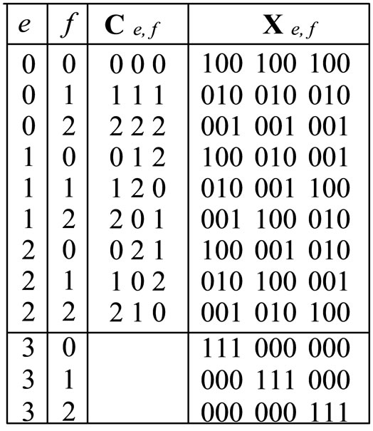
Table 1. The SP codewords for p=3.
after simply down-conversion process, encode these radio signals with the assigned SP codewords. The resulting encoded optical signals are combined in the 1 × M coupler and transmitted to the CBS through one fiber. Finally the decoders in the CBS receive the signals from the 1 × M coupler and extract the radio signal of each RBS for further processing.
In the following, the property of SP codes is briefly reviewed: One SP code ’s with length L = p2 used in this paper can be obtained from one modified stuffed shifted prime (MSSP) code with the same parameter p in [12] by eliminating the extra codeword and the last p+1 chips of each remaining MSSP codewords. For example, Table 1 shows the SP codewords for p = 3, and ,from [12], the cross-correlation between
  and
and  is
is
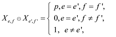 (1)
(1)
and thus
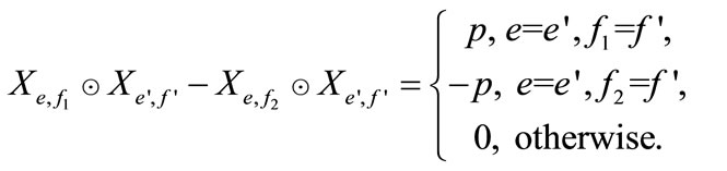 (2)
(2)
where ⊙ is the dot-product of two vectors. Since the RBSs can use the code property in Equation (2) for MAI elimination, any two distinct SP codewords with the same value of e can be assigned to one specific RBS for the encoding of radio signals, and the value of M is (p+1)(p-1)/2. However, the two codewords used for decoding in conventional SAC schemes are always complement to each other. Therefore, this coding scheme has the advantage of security enhancement in the SAC-based fiber radio networks since the eavesdroppers need to guess two codewords used for encoding.
3. Implementation of Coder/Decoder
The RBSs of the proposed fiber radio network use the encoder shown in Figure 2, which is designed for the first SP codewords  = [1 0 0 1 0 0 1 0 0] and the second SP
 = [0 1 0 0 1 0 0 1 0] of this RBS. Light from the broadband light source is incident to one FBG-based encoder cascading with another FBG-based encoder. Suppose that each wavelength chip has spectral width Δλ, the 3dB bandwidths of the FBGs in these two FBG-based encoders should also be Δλ. The center wavelengths of the FBGs in these two FBG-based encoders are { λ0, λ3, λ6 }(corresponding to
 ) and { λ1, λ4, λ7 }(corresponding to
 ), respectively. Therefore, the first (or second) codeword of this RBS is generated in
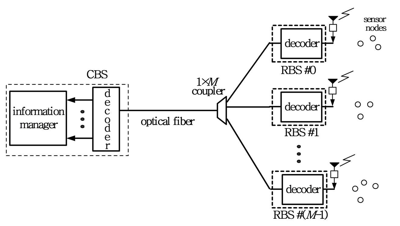
Figure 1. The proposed fiber radio network.

Figure 2. The encoder in the RBS.
the input port of the upper (or lower) intensity modulator (IM) and is intensity-modulated by the signal (1+ d(t))/2 (or (1-d(t))/2). Here d(t) is the radio signal normalized from the radio signal d’(t) such that max |d(t)| = 1. To make the receiver bandwidth B as small as possible, the frequency of the received radio signal from the antenna can be first converted to lower frequency before the signal manipulation process.
The decoder used to decode all the SP codewords from the RBSs with p = 3 is shown in Figure 3, which is similar to the AWG-based encoder in [11]. Two kinds of AWGs are used in this encoder: One is coarse AWG with free spectral range FSRc = p2 Δλ and channels bandwidth pΔλ, and the other is fine AWG with FSRf = pΔλ and channels bandwidth Δλ [9]. Note that the center wavelengths of the first output port at the coarse AWG are λc - FSRf ± r FSRc (r =0,1,…), thus there is only one coarse AWG channel at each coarse AWG output port within the encoded spectrum. However, for the fine AWG, the center wavelengths of the AWG channels that route from the first input port to the first output port are λ0 = λc- (p-1) Δλ/2 ± sFSRf (s = 0,1,…), thus there are p wavelength channels within the encoded spectrum that communicates between any input-output port pair.
The general principle to construct the decoder for one SP code family ’s with code length L=p2 is described as follow: the single light source is connected to one 1× (p + 1) splitter. The output port # e (e = 0 ~ p - 1) of the splitter is connected to one coarse AWG cascaded with one fine AWG and the output port #i of the coarse AWG is connected to the input port #
 (i) of the fine AWG. Take the encoder (p = 3) in Figure 1(a) as example, light emitted from the filtered light source contains wavelength componentsλ0~λ8 (Δλ=λi-λi+1 ) and is split into four. At these four encoder branches, wavelength chips λ0+bp, λ1+bp and λ2+bp are demultiplexed and appear at the output port # b of the coarse AWGs. Due to the connections between the coarse and fine AWG ports described above, λf⊕0, λp+ (f⊕1) and λ2p+(f⊕1) (f = 0, 1, ….,p-1) corresponding to X0, f appears at the fine AWG output port # f at encoder branch #0 and λf⊕1, λp+(f⊕0) and λ2p+(f⊕1) corresponding to X1, f appears at the fine AWG output port # f at encoder branch #1(⊕ denotes the modulo-p addition). Let’s take the generation of X1,0 as example. Wavelengths λ0, λ3 and λ6 from the light source are demultiplexed by the coarse AWG at encoder branch #1 and they appear at the output port #0, #1 and #2, respectively. The output ports # 0, #1 and #2 of this coarse AWG are connected to the input ports #0, #1 and #2 of one fine AWG according to
 (= [0 1 2]), respectively, and thus λ0, λ3 and λ6 appear at the input ports #0, #1 and #2 of this fine AWG, respectively. Since wavelength λg from the input port # i appears at output port # (g⊕(-i)) for each fine AWG [9], λ0, λ3 and λ6 all appears at output port #0 of this fine AWG which corresponds to X1, 0 = [100100100].
In this way, the first p2 codewords can be obtained at the fine AWG output ports of the encoder. Since the wavelengths appeared at the coarse AWG output port # f of the last encoder branch correspond to X3, f, the remaining p additional codewords in group #3 are obtained. Balanced detection for each RBS’s signal can be accomplished with one balanced detector shown in Figure 3. The upper and lower photo-diodes of the balanced detector for one RBS are connected to the fine AWG output ports in the decoder according to the first and second codewords assigned to that RBS, respectively. Thus each balanced photo-detector can generate electrical current proportional to the value of  and the MAI elimination scheme in Equation (2) is realized, where S is the summation signals from all RBSs.
4. Performance Analysis
Assume the light source in the RBS is unpolarized and has flat spectrum for encoding with bandwidth  and magnitude Psr/
 , where Psr is the effective power received by the photo-diodes in the decoder of the CBS. The average carrier power in the balanced detector is Pc=R2
 /(2p2), where R is the responsivity of the photodiodes. For the fiber radio network adopting SP codes, the PSD of the upstream optical signal arrived at the input port of the decoder in the CBS can be written as [5,10]
 (3)
(3)

Figure 3. The decoder for SP codes in the CBS.

Figure 4. CNR vs. Psr.
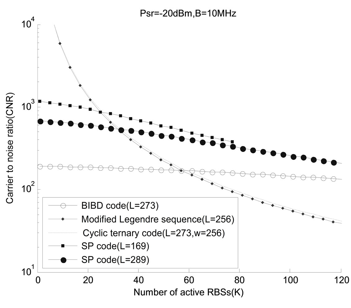
Figure 5. CNR vs. K.
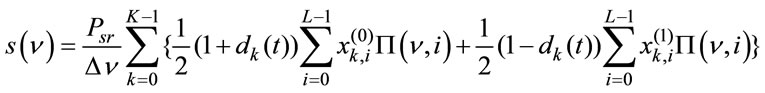
where
 (4)
(4)
Here K is the number of active RBSs and  is the normalized radio signal of k-th RBS. To simplify the notation, the i-th chip of the first and second codewords of k-th RBS are denoted as
 ![]() and
and , respectively. Assume the sensor nodes use modulation with constant envelope such as phase shift keying. If at this time only one sensor node transmit signal to the 0-th RBS, the radio signal is approximately a sine wave and the assumption of time average amplitude < d0(t) > = 0 and time average power < d0(t)2> = 0.5 can be used [5,6]. Thus the power of phase-induced intensity noise (PIIN) can be obtained [5,10]:
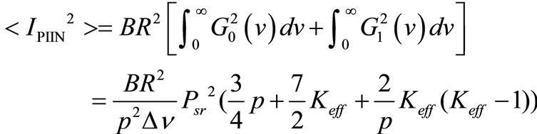 (5)
(5)
where B is noise-equivalent electrical bandwidth of the receiver. The effective number of interfering active RBS is [11]
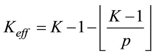 (6)
(6)
For wireless sensor networks using the 915MHz industrial, scientific, and medical (ISM) band for radio frequency transmission, the data rate may be just about 10k Hz. [1] Therefore, the carrier frequency of the radio signals received by the RBSs can be converted to about 10MHz by the frequency down-conversion circuit in the Figure 2, and B is set to 10MHz here. Other parameters used in the performance analysis are R = 0.8A/W, Δv = 7.5 THz, and v0 = 193.1THz and the power of thermal noise is
The relationship between CNR and K are shown in Figure 4. Here the results for other three codes (e.g. balanced incomplete block design (BIBD) codes, modified Legendre sequences mentioned in [6] and cyclic ternary sequences with weight w =256 in [6] are also shown for comparison and their code lengths are approximately the same. (Note that Hadamard codes in [5,7] obtain the same performance as modified Legendre sequences, and thus only the results for modified Legendre sequences are shown here.) When Psr is low, the influence of PIIN is less and the CNR for each code increases with Psr. This increase gradually disappears due to the domination of PIIN. The CNR curves for modified Legendre sequences and cyclic ternary sequences are approximately the same and these two codes obtain better CNRs then BIBD and SP codes when Psr is low. However, when Psr is high, the situation is reversed. Though the BIBD code obtains slightly better CNRs than SP code with similar length when Psr is larger than -15dBm, it requires very high transmitted power from the light sources in the RBSs when the insertion losses in the encoder/ decoder are taken into consideration. Since the insertion losses of FBG-based encoder in one RBS and the AWG-based decoder in the CBS are approximately 30dB [11], the CNR performance for Psr approximately -20dBm seems more important when the transmitted power from the light source in the RBS is about 10dBm [1], and SP code with L=289 obtains better CNR at Psr = -20dBm for K = 100.
The relationship between CNR and K for the codes in Figure 4 is shown in Figure 5, where Psr is set at -20dBm. It is found that all four codes obtain lower CNR when K increases. When K is relatively small, modified Legendre sequences and cyclic ternary sequences obtain better CNRs then BIBD and SP codes. However, the situation is reversed when K is relatively large. Though SP codes obtain better CNRs than BIBD codes for Psr = -20dBm, the corresponding cardinality is about half of that for BIBD codes with similar code lengths. Since SP codes can use AWG routers with smaller sizes for decoder implementation in the CBS as compared to BIBD codes, it is necessary to consider the tradeoffs between these codes for better network design.
5. Conclusions
One fiber radio scheme for the application of wireless sensor networks is proposed for optical code-division multiple-access (OCDMA) network. By the use of this fiber radio scheme, the design of sinks in the wireless sensor networks can be simplified, which has advantages for temporary deployment of the sensor networks. In addition, the proposed decoder in the CBS is compact and these features make the proposed fiber radio scheme more attractive for further research.
REFERENCES
- H. Kim, J. M. Cheong, C. H. Lee, and Y. C. Chung, “Passive optical network for microcellular CDMA personal communication service,” IEEE Photonics Technology Letters, vol. 10, no. 11, pp. 1641–1643, November 1998.
- I. F. Akyildiz, W. Su, Y. Sankarasubmmaiam, and E. Cayirci, “A Survey on sensor networks,” IEEE Communication Magazine, vol. 91, no. 8, pp. 102–114, August 2002.
- K. Tsukamoto, T. Higashino, T. Nakanishi, and S. Komaki, “Direct optical switching code-division multiple-access system for fiber-optic radio highway networks,” IEEE Journal of Lightwave Technology, vol. 21, no. 12, pp. 3209–3220, December. 2003.
- B. K. Kim, S. Park, Y. Yeon, and B. W. Kim, “Radio-over-fiber system using fiber-grating-based optical CDMA with modified PN codes,” IEEE Photonics Technology Letters, vol. 15, no. 10, pp. 1485–1487, October 2003.
- T. Demeechai, “Noise-limited performance of spectral-amplitude-coding optical CDMA in fibre-optic radio highway networks,” IEE Proceedings of Optoelectronics, vol. 152, no. 5, pp. 269–273, October 2005.
- C. C. Yang, “Optical CDMA fiber radio networks using cyclic ternary sequences,” IEEE Communications Letters, vol. 12, no. 1, pp. 41–43, January 2008.
- M. Kavehrad and D. Zaccarin, “Optical code-division-
- multiplexed systems based on spectral encoding of noncoherent sources,” IEEE Journal of Lightwave Technology, vol. 13, no. 3, pp. 534–545, March 1995.
- X. Zhou, H. M. H. Shalaby, C. Lu, and T. Cheng, “Code for spectral amplitude coding optical CDMA systems,” Electronics Letters, vol. 36, pp. 728–729, April 13, 2000.
- B. Glance, I. P. Kaminow, and R. W. Wilson, “Applications of the integrated waveguide grating router,” IEEE/OSA Journal of Lightwave Technology, vol. 12, pp. 957–962, June 1994.
- C. C. Yang, “The application of spectral-amplitude-codi-
- ng optical CDMA in passive optical networks,” Optical Fiber Technology, vol. 14, no. 2. pp. 134–142, April 2008.
- C. C. Yang, “Optical CDMA passive optical network using prime code with interference elimination,” IEEE Photonics Technology Letters, vol. 19, no. 7, pp. 516–518, April 2007.
- C. C. Yang, J. F. Huang, and T. C. Hsu, “Differentiated service provision in optical CDMA network using power control,” IEEE Photonics Technology Letters, vol. 20, no. 20, pp. 1664–1666, October 2008.
NOTES
* Phone: 886-6-2050521 ext 3509, Fax: 886-6-2050250.