Journal of Software Engineering and Applications
Vol.08 No.09(2015), Article ID:59383,7 pages
10.4236/jsea.2015.89043
A Review of Telemetry Data Transmission in Unconventional Petroleum Environments Focused on Information Density and Reliability
Ivamberg Navarro de Almeida Jr.1, Pedro Duarte Antunes1, Felipe Orlando Centeno Gonzalez1, Roberto Akira Yamachita1, Andreas Nascimento2, Jose Luiz Goncalves1
1Instituto de Sistemas Elétricos e Energia, Universidade Federal de Itajubá (ISEE/UNIFEI), Itajubá, Brazil
2Departamento de Engenharia Mecânica/PRH48, Faculdade de Engenharia, Câmpus de Guaratinguetá, Universidade Estadual Paulista (FEG/UNESP), Guaratinguetá, Brazil
Email: ivannavarrojr2@hotmail.com, andreas.nascimento@gmail.com
Copyright © 2015 by authors and Scientific Research Publishing Inc.
This work is licensed under the Creative Commons Attribution International License (CC BY).
http://creativecommons.org/licenses/by/4.0/


Received 30 July 2015; accepted 1 September 2015; published 4 September 2015
ABSTRACT
The paper addresses a literature review of the technologies used in the transmission of measuring and logging data during well drilling. It presents a discussion about efficiency in data density transmission and reliability, especially when it comes to software and automated tools. Initially, this paper analyzes the principle of the telemetry systems, considering the mud pulse telemetry, acoustic telemetry, electromagnetic telemetry and wired drill pipe telemetry. They were detailed highlighting information about functionality, data transmission and its linkage to supporting software. Focus is also given to details of the main advantages and disadvantages of each technology considering the influences of lithology, drilling fluid and formation fluids in the reliability and capacity of data transmission.
Keywords:
LWD, MWD, Mud-Pulse, Wired-Drill-Pipe, Drilling, Fluid, Telemetry, Transmission

1. Introduction
Overall in a drilling activity, since it concerns a combination of several systems and machineries together in which communication and right information transmission through a chain implies a very important role, one can consider that the probability of encountering petroleum accumulations are around 30% in general. For the development of an entire field, 10% - 20% of the cost can be related to the exploration phase, 50% to the development phase and the remaining 30% - 40% to the production phase and related logistics. And from this exploratory phase, 40% - 80% is specifically related to the drilling (4% - 16% of the total field cost). Thus, this summarized figures point out how the exploratory drilling activity itself may have an economical impact in the overall operation, making it necessary to have an “eye” down-hole in order to accurately drive and control operation away from unforeseen events. Moreover, as one of the universal using methods for transmitting information from down-hole to the surface, the different telemetry systems have allowed the industry to overcome these obstacles [1] [2] .
In this sense, this paper will initially verify and analyze the principle of the telemetry systems, considering the mud pulse telemetry, acoustic telemetry, electromagnetic telemetry and wired drill pipe telemetry. They were detailed in a sense to point out the idea behind each one of them, highlighting information about functionality, data transmission and its linkage to supporting software.
Further, technical articles were collected in order to have a better approach about the theory and practical applicability in the industry, accomplished by researching directly with the equipment manufacturers such as Schlumberger, Halliburton, Baker Hughes and National Oilwell Varco (NOV). The paper details the information and processes with focus on the following aspects: data transmission capacity, transmission speed, signal attenuation factors, reliability and applicability―defining at the end the best technology that may be applied for ultra-deep related operations.
2. Technology System Analysis
2.1. Electromagnetic Telemetry
The geological formations are typically not homogeneous and quite different. Each formation has unique properties that affects the transmission of electrical signals and which varies with the depth, spacing, and sequence of different types of geological layers, among others. The electrical properties of the drill-string also dynamically vary with length, constitution of the drilling fluid and temperature.
In this context, the electromagnetic telemetry adapts to the electrical environment encountered in the well by means of a microprocessor in a monitoring tool, which continuously scans the frequency spectrum with electromagnetic signals to determine the optimum frequency for data transmission between the tools and processing units (computers) on the surface. This transmission can be achieved by both through the drill-string body or through the formation being drilled. Figure 1 shows a general electromagnetic telemetry system.
By determining the relative attenuation of the transmitted signal, the operator at the surface can send a command back to the tool (or vice-versa) to replace the frequency of the carrier wave with one that may suffer less attenuation and which may have a better signal to noise ratio. For example, highly resistive formations below the drill-string cannot function as ground and the drill-string itself must then be treated as a vertical dipole. In this case, the most effective frequency for the carrier wave would be one resonant with the drill-string, identified by the tool as the one drawing maximum input current. The most frequently used optimal selection technique is one in which the receiver periodically sends recognition signals to the transmitter, so that when this signal is not captured by the same transmitter, it changes the carrier wave frequency gradually decreasing it until it returns capturing the recognition signals from the receptor. However, by lowering the frequency of the carrier wave, the amount of transmitted data is consequently diminished. In this case the tool in the well has to be programmed to transmit only the most critical information relevant to the operation [4] .
The first papers on electromagnetic telemetry were quite promising, claiming that rates of up to 100 bits per second (bps) could be achieved with the use of signal repeaters. However, the development of mud pulse telemetry in parallel on the market brought more efficient results, with higher data transmission rates reaching greater depths, without the needs of repeaters usage. The huge attenuation suffered by the electromagnetic signals, caused by the formation properties, drilling mud and surface conditions led to a decline of this technology. Another aspect restricting this technology is the water. Due to its high electrical conductivity, it limits the use of electromagnetic telemetry in offshore operations with large water depths, making it to be relegated just to the oil & gas (O&G) market onshore and for shallow depths, considering the low transmission rates (SCHNITGER, 2009). On the other hand, in activities where usual drilling mud may not be used, alternatives are to use aerated

Figure 1. Electromagnetic telemetry system [3] .
fluid or foams. In these specific cases, it is preferable to have electromagnetic since it allows a better transmission rate in comparison to mud pulses, but even, it is limited to approximately 9000 [ft.] depth.
2.2. Acoustic Telemetry
The acoustic telemetry system is operated with batteries and is distinguished from other systems since it works by generating acoustic waves capable of transmitting real-time data to the surface through the walls of pipes at distances up to 12,000 [ft.]. A variety of data can be acquired and transmitted: pressure, temperature, time, command and information about the system status. This telemetry system is used mainly in exploratory wells and also for well-testing operations. Meters equipped with quartz crystal sensors located just above the tester valve generate accurate signals of temperature and pressure in the deep end, being stored in recording memory or directly transmitted to the surface. Each quartz sensor is able to store up to 440,000 readings in its memory, and the entire system is capable of storing more than 1.3 million scans, allowing great flexibility.
In real-time, the transmitter sends packets of data with all information acquired in every two minutes directly to the next repeater. A packet is a group 12 acoustically transmitted data sets, each set containing pressure information, temperature and time for sample intervals of 10 seconds. The repeater then forwards the packet to the surface to be decoded. The system is able to communicate in both directions, allowing the operator to send additional commands on the surface below to the system, for example, if any changes have to be done. Figure 2 exemplifies the acoustic telemetry system.
In wells deeper than 12,000 [ft], more repeaters are necessary but is not as straight forward as it looks like due to the “cross talk” problem (unwanted interference of a transmission channel to another). Moreover, in such environment the great difficulty lies in transmitting the acoustic signals to the surface through the docking column, which due to its size and components can cause large attenuation. Therefore, the acoustic signal is brought up to the sub transducer surface, and from there converted into an electrical signal and transmitted through a twisted pair cable to the surface. In 2011, XACT Downhole Telemetry Inc. published a study on its acoustic telemetry module capable of transmitting data to a 20 [bps] rate in wells up to 2500 [m] [7] .
2.3. Mud Pulse Telemetry
This technology employs a module that modulates resistance to the flow of the drilling fluid through the inside of the drill-string, generating an increase and decrease of the stand-pipe pressure and so the mud pressure pulses representative of the parameters measured by the logging tools and that is propagated, approximately, at the speed of sound to surface. Transducers located on the surface detect and convert the pressure signal into a digital electrical signal through analog/digital (A/D) converters. This signal is then sent to a computer that will process and decode the signal received through specific and developed software to recognize and treat these signals [8] [9] .
In an ideal system, each pressure pulse created by the module would spread column up and would be easily

Figure 2. Flow-chart of a acoust telemetry system operation [6] .
detected by transducers, but, however, the pressure of the drilling fluid undergoes significant fluctuations and containing noises from various sources such as the drill noise, noise from the torque and from the mud pumps itself, etc. The drill noise is caused by its vibration during the drilling operation, which partially restricts the output of drilling fluid causing a high-frequency noise. Torque noise is caused by the increase in drill string torque when the drill is in contact with the formation; after contact, the torque in the column is relieved generating a peak of large amplitude and low frequency pressure. Finally, mud pump noises are due to the cyclical piston movement for displacing mud into the circulating system.
Some drilling systems use a buffer on the surface to reduce noise caused by the mud pump, but the pulsation dampener can also be adjusted for that. However, while they absorb some of the pressure fluctuations, they also act as a mirror, reflecting pressure pulses back to the telemetry module, sometimes destructively, creating interference and hindering or making the detection of pulses by the transducer in surface more difficult. A basic telemetry module contains two sections: one for communication and other for control of the generated pulses. The various logging tools send their data to the digital signal processor (DSP) located in the communication section. The processor operates according to software stored in memory in order to convert the data as a digital signal. A compression module reduces the amount of data transmitted over techniques involving the removal of certain data. It is also used differential encoding which allows a data string to be represented with fewer or less bits than usual (Emmerich, 2015).
The multiplexing module selects the data of the different tools and assembles a single chain of data being transmitted, divided into blocks that can contain information about synchronization and error correction. A coding module then converts the digital signal channels to be transmitted on a set of timings that are communicated to the pulse control section for generating them. The pulse control section consists of a processor, memory, an opening coil, closing coil, two banks of capacitors and battery. The control pulses operate a valve through the opening and closing coils generating the pressure pulses. The coils drain relatively high amounts of current in operation, in some cases more than the battery can deliver. Its power though must be within the operating capacity of the battery. To solve the problem of the current supply, each reel is associated with a capacitor bank. The battery charges the capacitors between the operations of the reels, and when the processor activates the reels they unload supplying current making the valve operation possible [8] [9] .
The valve that creates pressure pulses can have different shapes and constructions, being classified among different types in terms of operating system. The three most common used types are: positive pulse (Figure 3(a)), negative pulse (Figure 3(b)) and continuous pulse (Figure 3(c)). Any one of three types can be used provided that the valve can produce variations quickly enough (in the order of [ms]). The duration of the pulses may vary from 80 [ms] until approximately 400 [ms], depending on the drilling system parameters (Honório, 2007). In the positive pulse, the equipment creates a restriction in which the stand-pipe pressure increases. In the negative


 (a) (b) (c)
Figure 3. Mud pulses: positive (a), negative (b) and continuous (c) [3] .
one, the equipment allows part of the flow to leak to the annulus, creating a pressure decrease. Finally, in the continuous one, there is a modulator and a stator creating restrictions and reliefs continuously.
2.4. Technological Advances
In 2008, Baker Hughes INTEQ published an article [10] suggesting major changes in conventional mud pulse telemetry systems. These changes included the use of an oscillating shear valve rather than rotational, capable of generating pressure pulses at the appropriate frequency for the well conditions and the use of two pressure transducers on the surface, rather than just one. The movement of this new valve had considerable impact on signal quality sent from down-hole, to the extent that it eliminates the time necessary to accelerate/decelerate the rotational valve during a frequency change for generating the bits, having the frequency exchanged instantaneously. This is a considerable advantage, since the whole bandwidth could be used for data transmission. Figure 4 illustrates this improvement.
Another important change was the use of calibration routines which were capable of monitoring the well conditions and automatically updating the data processing algorithm according to the current condition, improving process efficiency. These changes were tested in several critical wells around the world achieving an increase in data transfer-rate of approximately 200% with a 40 [bps] rate deep up to 24,000 [ft.].
In 2009, Schlumberger launched the Orion II [11] telemetry platform in order to increase the information transmission rate within the same [bps] by means of a compression algorithm. Modulation techniques are also used so that the signals are able to have greater range. Rather than just compressing the individual pieces of well profiles, Orion II compression system compresses all the signal profile, ensuring optimal compression ratio without compromising the quality of the recorded data. From the normal transmission rate of 12 [bps], this technology allows an equivalent transmission of 120 [bps].
2.5. Wired-Drill-Pipe Telemetry
This technology uses individually modified drill-pipes to provide a two-way telemetry system for real-time transmission, speeding up to 57,000 [bps], making possible to obtain large amounts of data from down-hole (Bybee, 2008). The technology uses high strength coaxial cables and low-loss inductive coils built in connections on each tubular joint to transmit information. Signal repeaters are placed at specific locations along the drill-string to ensure an acceptable signal to noise ratio. These repeaters operate as individually accessible nodes within the telemetry network, and thus, being able to identify sites that can provide potentially valuable measuring data. Figure 5 shows a schematic of the mentioned wired drill pipe, focusing on its threads.
A bi-directional network architecture, which is this specific case, allows the transmission of downhole data to the surface at high speed while commands can still be sent from the surface to the equipment itself. By inserting a physical and electrical interface, existing logging-while-drilling (LWD) and measuring-while-drilling (MWD) tools become fully compatible. Although there are small variations between tools from each manufacturer, the interfaces are generally consistent in the industry: it involves a network inductive connection at the top, a suitable electromechanical coupling on the bottom, a network card, modem and a power source.

Figure 4. Bandwidth: rotational and oscillating valve [10] .
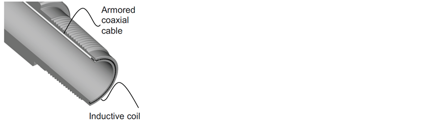
Figure 5. Wired-drill pipe joint [12] .
3. Cross-Analysis and Discussion
For each technology, from different manufacturers data were obtained, as well as case studies, and recent articles that could be representative of what's latest in a given technology were also combined resulting in a critical understanding. The electromagnetic telemetry is represented by Halliburton’s system―Sperry Drilling’s EMT [13] ; the acoustic telemetry by Acoustic Telemetry System (ATS) from Halliburton [5] ; the mud pulses telemetry by the TeleSCOPE system integrated with Orion II platform [11] , both from Schlumberger; and finally, the wired-drill-pipe telemetry represented by IntelliServ Network system [14] from National Oilwell Varco. Table 1 compares the telemetry systems in means of transmission rate, maximum reached depth, amount of data transmitted and technology cost.
Analyzing Table 1, it can be noticed that for ultra-deep wells with depths greater than 6000 [m], the electromagnetic and acoustic telemetry technologies are not applicable due to the depth restriction caused by the large attenuation of the signal in these conditions. Even by using signal repeaters, these technologies would be limited by 18,000 [ft.].
However, mud pulses telemetry and wired-drill-pipes follow technologically, advancing and increasingly hitting depth records with very efficient transmission rates. It is remarkable the huge difference between the ability to transmit data of these technologies, but this difference is mitigated by the high cost of wired-drill-pipes. Due to the fact that the cost of this system is directly proportional to the depth of the well, its application should be

Table 1. A comparative between different data transmission technologies.
restricted to high-valuable wells with return already guaranteed, which is not the case of exploratory wells. Thus, some attention is driven to the telemetry system based in mud pulses as the most feasible one in general, enabling acquisition of essential information with reasonable transmission rates.
4. Conclusions
The drilling activities in ultra-deep require profiling data telemetry technology that is both efficient and inexpensive, whereas in exploratory wells, field’s production potential may not yet be determined in its totality. It is important to note that telemetry technology for wired-drill-pipe despite being extremely efficient from a technical point of view, has a high cost of installation and maintenance. Currently, mainly due to the oil market crisis, a consequence of the oil price droopiness, it is extremely important to cut spending.
In this sense, telemetry technology through drilling mud pulses is still the leader due to the low-cost implicit in this technology, with well depths reaching above than others. By reinventing itself in the recent decades, it is now able to achieve high transmission rates with higher data density. The idea is then to develop new data compression algorithms and processing and signal modulation techniques allowing a way ahead for greater depth, enabling an efficient profiling with high cost effectiveness.
Nevertheless, despite of all this fact, it is very important to mention that the unit processing still has to be developed in parallel in order to be able to process all these data in a timely manner, allowing real-time decision making, either directly in the field or even remotely.
Acknowledgements
The authors acknowledge the financial support of Brazilian National Petroleum Agency (ANP) by means of Human Resource Program for the oil and gas sector (PRH).
Cite this paper
Pedro DuarteAntunes,Felipe Orlando CentenoGonzalez,Roberto AkiraYamachita,AndreasNascimento,Jose LuizGoncalves,Ivamberg Navarro de AlmeidaJr., (2015) A Review of Telemetry Data Transmission in Unconventional Petroleum Environments Focused on Information Density and Reliability. Journal of Software Engineering and Applications,08,455-462. doi: 10.4236/jsea.2015.89043
References
- 1. Nascimento, A. and Nogueira, L.A.H. (2010) Exploração de petróleo em camadas do Pré-sal no Brasil: Um estudo de caso no Poço 1-SPS-50. Master Thesis, Universidade Federal de Itajubá, Instituto de Sistemas Elétricos e Energia, Itajubá.
- 2. Thomas, J.E., et al. (2004) Fundamentos de Engenharia de Petróleo. 2nd Edition, Interciência, Rio de Janeiro.
- 3. Hughes, B. (1997) White Paper. INTEQ’s Guide to Measurement While Drilling. USA.
- 4. Schnitger, J. and Macpherson, J. (2009) Signal Attenuation for Electromagnetic Telemetry Systems. SPE/IADC Drilling Conference and Exhibition, Amsterdam, 17-19 March 2009.
http://dx.doi.org/10.2118/118872-ms - 5. Halliburton. White Paper. Acoustic Telemetry System. www.halliburton.com
- 6. Harper, G., Almanza, E., Fossa, A., Finley, D. and Srang, E.G. (2003) Acoustic Telemetry System Provides Real-Time Data Acquisition. Proceedings of Offshore Technology Conference, Houston, 5-8 May 2003.
- 7. Neff, J.M. and Camwell, P.L. (2007) Field-Test Results of an Acoustic MWD System. IADC/SPE Drilling Conference, Amsterdam, 20-22 February 2007. http://dx.doi.org/10.2118/105021-ms
- 8. Emmerich, W., Akimov, O., Brahim, I.B. and Greten, E.A. (2015) Reliable High-Speed Mud Pulse Telemetry. IADC/ SPE Drilling Conference, London, 17-19 March 2015.
- 9. Honório, M.C. and Bortoni, E.C. (2007) Qualidade dos Dados Transmitidos Durante a Perfuração de Poços de Petróleo. Master Thesis, Universidade Federal de Itajubá, Instituto de Sistemas Elétricos e Energia, Itajuba.
- 10. Klotz, C., Bond, P. and Wasserman, I. (2008) A New Mud-Pulse Telemetry System for Enhanced MWD/LWD Applications. IADC/SPE Drilling Conference, Orlando, 4-6 March 2008.
- 11. Schlumberger. White Paper. Orion II. www.slb.com/Orion2
- 12. Bybee, K. (2008) High-Speed Wired-Drillstring Telemetry. Journal of Petroleum Technology, 60, 76-79.
http://dx.doi.org/10.2118/1208-0076-jpt - 13. (2012) Halliburton Sperry Drilling EMT. Halliburton. www.halliburton.com
- 14. NOV, National Oilwell Varco. White Paper. IntelliServ Network. www.nov.com/intelliserv