Journal of Software Engineering and Applications
Vol.6 No.5(2013), Article ID:31297,7 pages DOI:10.4236/jsea.2013.65028
Deploying Safety-Critical Applications on Complex Avionics Hardware Architectures
![]()
1Fraunhofer Institute for Open Communication Systems (FOKUS), Berlin, Germany; 2Liebherr-Aerospace Lindenberg GmbH, Lindenberg, Germany.
Email: robert.hilbrich@fokus.fraunhofer.de, laurent.dieudonne@liebherr.com
Copyright © 2013 Robert Hilbrich, Laurent Dieudonné. This is an open access article distributed under the Creative Commons Attribution License, which permits unrestricted use, distribution, and reproduction in any medium, provided the original work is properly cited.
Received March 22nd, 2013; revised April 20th, 2013; accepted April 28th, 2013
Keywords: Avionics; Systems Engineering; Software Deployment; Software Architecture; Safety-Critical Systems
ABSTRACT
Aviation electronics (avionics) are sophisticated and distributed systems aboard an airplane. The complexity of these systems is constantly growing as an increasing amount of functionalities is realized in software. Thanks to the performance increase, a hardware unit must no longer be dedicated to a single system function. Multicore processors for example facilitate this trend as they are offering an increased system performance in a small power envelope. In avionics, several system functions could now be integrated on a single hardware unit, if all safety requirements are still satisfied. This approach allows for further optimizations of the system architecture and substantial reductions of the space, weight and power (SWaP) footprint, and thus increases the transportation capacity. However, the complexity found in current safety-critical systems requires an automated software deployment process in order to tap this potential for further SWaP reductions. This article used a realistic flight control system as an example to present a new model-based methodology to automate the software deployment process. This methodology is based on the correctness-by-construction principle and is implemented as part of a systems engineering toolset. Furthermore, metrics and optimization criteria are presented which further help in the automatic assessment and refinement of a generated deployment. A discussion regarding a tighter integration of this approach in the entire avionics systems engineering workflow concludes this article.
1. Introduction
1.1. Current Trends in the Avionics Domain
In the last ten years, with the spreading of the Fly-byWire technology, the infrastructure of modern aircrafts has been significantly optimized by reducing the amount of mechanical and hydraulic components. This engineering trend helped to decrease the weight and increase the transportation volume. By helping to reducing the CO2- footprint, it also contributed to reduce the impact on the environment.
Today, the aviation electronics (avionics) in modern aircrafts realizes more and more safety-critical functions for pilot assistance, comfort and maintenance, like landing facilitation, flawless coordination between flying surfaces or centralized diagnostics. Due to this growing complexity, today too many parameters must be considered to perform manually a real optimized deployment of functions on the hardware architecture without taking the risk of transgressing safety requirements. By “deployment”, we refer to the process of creating a mapping between software components and hardware components. Due to the complexity of the avionics hardware architectures and the variety of non-functional requirements affecting a deployment, its construction is an intricate and costly task.
Thus, the hardware architecture is deliberately oversized to ensure the coverage of all potential aspects. The efficiency of this method is strongly influenced by the experience and the intuition of the project engineers. This has direct consequences to the size of the system architecture which makes growing the avionics infrastructure. Moreover it increases the complexity of system design and integration effort, thus directly impacting the timeto-market of new products and the reusability of currently used components. Furthermore, this growing complexity incommodes a validity assessment in an early development phase of the chosen architecture as more components must be analyzed under crucial aspects like safety, timing and reusability.
In this article we describe an approach to address this engineering complexity which was jointly developed between Liebherr-Aerospace Lindenberg GmbH and Fraunhofer FOKUS. It is based on the underlying princeple, that hardware resources of an airplane can be used more efficiently, if system functions are deployed in such a way, that they use optimally the resources of single devices, enabling these devices to provide its resources for more than a single function. In this way, a noticeable reduction of the hardware architecture is expected, which will pursue the decrease of weight and energy needs and consequently increase the transportation capacity of new generation of aircrafts.
Here, we primarily focus on safety requirements alongside other non-functional requirements, which are of particular importance for the avionics domain.
1.2. Research Objectives
In a research project, Fraunhofer FOKUS and LiebherrAerospace addressed the challenge of automating and optimizing the deployment of safety-critical avionics software onto avionic hardware. A deployment in general refers to the assignment of hardware resources, e.g. CPU time, memory or I/O to software components. We distinguish between a spatial and a temporal deployment (see Figure 1). The former focuses on the entire system architecture and leads to a mapping from a software component to a set of hardware resources, e.g. a processor or an electronic control unit. The latter concerns the aspect of schedulability for each hardware resource. It addresses the question of when to execute a software component on the previously assigned hardware resource. A deployment is correct, if the proper amount and proper type of resources is assigned to all software components at the right time. It is the job of the operating system to properly perform the designed temporal deployment at runtime.
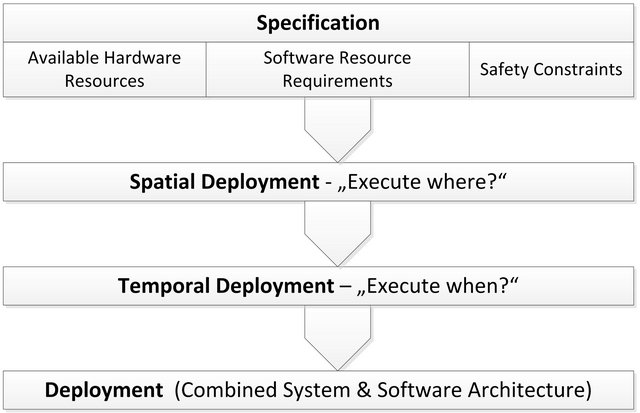
Figure 1. Spatial and temporal deployment.
While a lot of current research deals with temporal deployment and schedulability analysis [1-3], we focused on a spatial deployment in a safety-critical domain. Fundamentally, a spatial deployment has to match available hardware resources with resource requirements of software components and satisfy external constraints, such as safety. Additionally, it is also the starting point for extensive optimizations on the system level as it has a direct impact on the cost and the performance of the system. Determining an optimized deployment is not only challenging as it is in the complexity class NP-complete. It is also a very sensitive part of the engineering processes as it immediately affects real-time and safety properties of the entire system.
We set out to use a model-based approach to capture key parameters and formalize this allocation problem in order to automate the deployment and guarantee its correctness. In the avionics domain, an automated deployment is mainly beneficial during the design phase of system and software architecture. A preliminary deployment in early stages would help the engineer to explore the available design space more efficiently by evaluating the effect of each design decision on cost and performance, and thus help to optimize the system architecture in concordance with the safety requirements.
2. Methodology
2.1. Use-Case: The Development of a Complex and Safety-Critical Flight Control System
Current aircrafts embed tens of computer systems to realize safe and efficient flight control systems. Allocating the computers to the system functions inside the flight control system architecture is usually simply done manually. Several tries are often made to reduce the number of devices, but the complexity, resulting from the diversity of hardware-software combinations in association with the safety requirements, also increases the cost of the validation process of the optimized solutions. Thus it represents too many engineering uncertainties in order to be able to realize manually more than only superficial optimizations.
The example bellow exposes the challenge based on a “federated architecture” [4]. For certification aspects this kind of architecture is still preferred for the realization of flight control systems against centralized architecture solutions. However, the underlying concepts of our methodology and the specific challenges being addressed apply to both avionic architecture types: to the federated architectures and to the Integrated Modular Avionics (IMA) architectures [5-7] as well.
The main challenge to optimize the system architecture of complex systems resides in mastering the amount of parameters affecting the deployment of the functions. The architecture is influenced by the hardware resource constraints and by the non-functional requirements of the system functions like validation requirements and safety constraints, e.g. redundancy or dissimilarity. With the growing number of functions realized by the avionics, it becomes increasingly challenging to design a safe system. The safest solution is to dedicate one device per critical function. This traditional design approach results in a complex network of small embedded computers which are partly independent to each other—hence its name “Federated Architecture”.
In a system architecture like shown in Figure 2, two or three actuators are associated to each flight control surface, synchronized or switched by specific redundancy management algorithms. Several surfaces are structurally redundant and act as backup to each other, and must still be redundant at the avionics level. The actuator allocation to the surfaces is derived from the safety requirements at the physical level. Each actuator will be driven by a separate control-loop function. Additional synchronization computers containing the main Flight Control Laws coordinate the different surfaces to establish the stability of the aircraft and to ensure the comfort for the passengers. Both are key features brought along by the Fly-by-Wire technology. Table 1 summarizes the amount
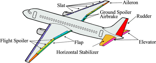
Figure 2. Primary and secondary flight control surfaces to be controlled by a flight control system.
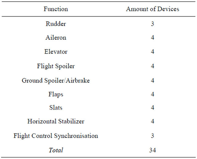
Table 1. Realistic example of a flight control system device infrastructure.
of devices being required for the implementation of a classical flight control system.
Traditionally, the well-known “Control Channel/Monitor Channel” architecture is used to simplify the safety assessment and certification for each flight control system function. This architecture style results in having two embedded computers within each device so that the total amount of computers being required for a classical flight control system may easily reach 60 and above. Moreover, the consequence of several safety constraints (redundancy, protection against common causes, independence…) induces that several boards and devices must be designed differently, must be separated in different places aboard an airplane and/or must be physically protected from each other.
To reach a significant reduction in space, weight and power requirements (SWaP), the challenge arises to reduce the number of devices of the today system infrastructure. This can only be reached by grouping functions or sub-functions and to mapping them “smartly” on a smaller number of devices without violating any safety requirement. A smart “multi-function-integration” is a key element to reduce the SWaP footprint for airplanes in the future.
2.2. Approach
The current practice in creating a spatial deployment in the avionics industry for highest safety critical functions is either by dedicating a device to a system function to minimize the risks concerning the safety and the resource limitation, whose result is not optimized, or by using an initial deployment—often taken from previous projects with sufficient similarities—with an iterative refinement process. This refinement process is steered by the results of an analysis regarding several criteria, for instance safety, cost or corporate policy & strategy. Due to the iterative nature and underlying complexity of the design space, this methodology is inefficient and inflexible. Although it may lead to a valid deployment satisfying all requirements, it is often not the best one possible. It is just the result of an initial deployment with an iterative analysis-based refinement afterwards. Therefore, the question whether this system could be built with less hardware components cannot easily be answered.
In our research project, we wanted to improve the current state of practice by applying the Correctness-byConstruction principle. This engineering principle has been pioneered by Chapman and Hall for the development of “high integrity software” [8,9]. Although it applies originally to the lifecycle of software components, we’ve extended this principle to the design of the system architecture. One of the main consequences is to concentrate at the system level the formalization of the deciding parameters which are traditionally not precisely expressed at this abstraction level and development phase. Therefore, we wanted to approach this research challenge with a model-based construction process in order to efficiently capture these deciding parameters and create valid and optimal deployments while significantly reducing the amount of iterative refinement cycles.
As a first step, we developed a Domain Model [10] to capture the relevant artifacts, entities and their relationships for a spatial deployment in the avionics domain. This model contained the following aspects:
• Relevant avionic hardware layers, their topology and performance capabilities;
• Relevant system functions requirements in form of avionic software application properties and their relationships;
• Safety and dependability requirements.
For the creation of the domain model, we discussed at length which properties of complex avionics system elements influence in which manner the deployment challenge and how these aspects are judiciously reflected in a model. For instance, some safety requirements refer to a geometrical location in an airplane. But instead of including an entire computer-aided design (CAD) model of the plane containing the exact geometrical location of each hardware node, we opted for simple string properties to annotate a location within an airplane. In order to assess the completeness of the model, we focused on “extreme” scenarios. Questions like “what would keep us from deploying all applications on a single processor?” quickly lead to missing pieces in our model.
A domain model also proved to be very helpful to determine which parts of the entire system architecture are assumed to be fixed, e.g. software components and hardware nodes, and which parts are subject to the variability of the deployment process, e.g. location of software components or processor load. Furthermore, we distinguished between “valid” deployments, which satisfy all given constraints and safety requirements, and “desired” deployments, which are also valid, but optimal with respect to given optimization criteria (see Figure 3). Here, the domain model was very helpful in defining metrics and heuristics for the construction of desired spatial deployments.
2.3. Capturing Safety Requirements as Software Deployment Properties
One of the key aspects to automate the deployment computation is the possibility to express the safety requirements and the deployment constraints in a simple, computer-interpretable form. To perform this, we first analyzed the human-understandable requirements from [11-13] precisely in real contexts were they must apply regarding a software deployment. Based on this analysis, we started to add attributes to our domain model for
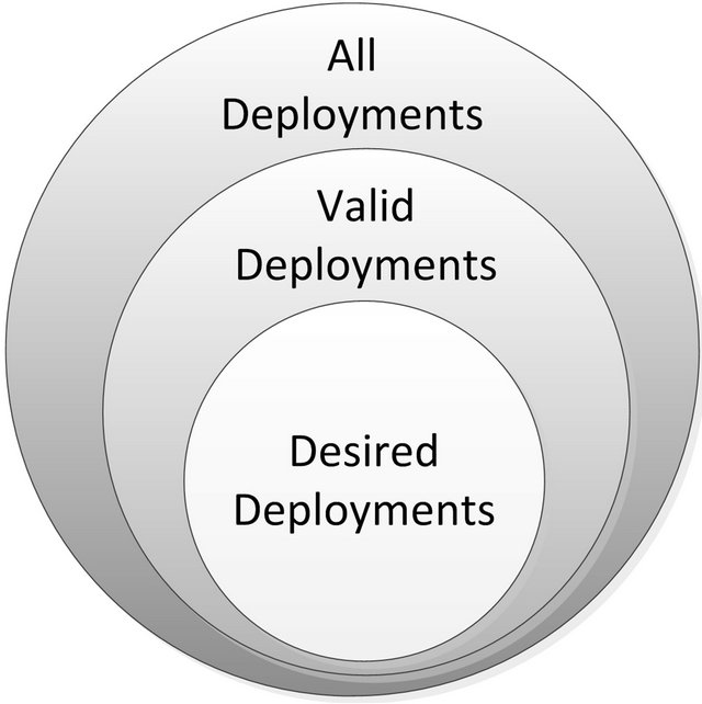
Figure 3. Valid vs desired deployments.
software applications. Table 2 contains these additional domain model attributes and the corresponding safety requirements.
This approach caused the addition of a specific “DAL” attribute for the software and hardware components, as well as a “Dislocality” and “Dissimilarity” relationship property between software applications. The “DAL” attribute annotates a quality level of development to hardware and software components. Additionally, deployment rules have been specified similarly as for the properties and formalize the engineer expertise. For example, during the deployment, the DAL requested by a software component has to be matched by the assigned hardware component which must offer the same or better DAL. “Dislocality” requires two software components to be deployed to two separate hardware components (different identity, same kind) and at two separate places. “Dissimilarity” on the other hand requires not only different hardware components with regard to their identity, but also different kinds of hardware (different identity, different kind) and different development teams. This can also affects the entire hardware infrastructure, so that dissimilar cabinets, boxes and boards can be required as well.
3. Deployment Generation and Analysis
After a potential spatial deployment has been specified either graphically or by using a domain specific language we derived from the domain model via XText [14], the engineer triggers the automatic deployment generation. The search algorithm applies a brute force approach to find all valid spatial deployment solutions deducted from the deployment rules. While this approach may not be suitable for larger problem sets due to the NP-complexity, it was sufficient for the problem size we were currently facing. Computing all valid deployments from about 15 applications onto six to eight different processor cores was achieved on a regular desktop computer in less than 5 seconds. Individual results are presented graphically to the engineer, so he can easily identify, which applications are assigned to which processor cores. Figure 4
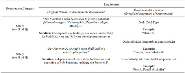
Table 2. Example for expressing additional safety constraints in the domain model.
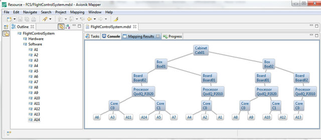
Figure 4. Automated software deployment generation.
contains a generated deployment for a fictitious flight control system.
We previously introduced the relevant distinction between all solutions, valid solutions and desired solutions (see Figure 3). The tool we developed in our research project follows a two-step approach. At first it generates a set containing all valid solutions. Depending on the constraints of the deployment problem, the result set may contain none, few or plenty of valid solutions. As an engineer is only able to manually seek through a small set of valid solutions, we develop specialized rules to automatically sort the result set and return a subset of desired solutions in a second step. This allows the engineer to quickly focus on the top ranking solutions among the set of valid solutions. The sorting of valid solutions is based on special deployment rules reflecting desired solutions. These rules may refer to a wide range of deployment properties, like system performance, component reusability or a cost function.
As example, an easy to understand rule is the one focusing on the proximity of applications. In the deployment specification, the engineer may describe the intensity of the data exchange between two applications as “none”, “low”, “medium” or “high”. This reflects a desired proximity between two applications and the need to reduce communication latencies. Therefore, applications which are communicating intensely should be deployed as “close” to each other as possible, although in principle a deployment of these applications to entirely different boxes or different cabinets may satisfy all safety requirements as well. In order to analyze all valid deployment solutions based on the communication intensity of all applications, we added a “proximity penalty” to each valid deployment. For each pair of applications in a deployment solution, the proximity penalty accumulates the product of the tree distance “d” between these two applications (see Figure 4) and their communication intensity factor “i” ( 0 for “none”, 1 for “low”, 3 for “medium” and 9 for “high”).
The penalty increases with the distance between two applications. It gets even worse when these two applications are communicating intensely with each other. Therefore, solutions with a minimal proximity penalty can be expected to better reflect a desired spatial deployment.
4. Discussion
This study was realized to explore our chosen principle to optimize the architecture of avionics systems, and these first results confirm our expectations. Further research on improved heuristics, more accurate formalization and enhanced search strategies are obviously still necessary to better capture the experiences and design preferences from the domain experts and tap the full potential of an automated spatial deployment process. However, we believe the results obtained so far are sufficient to focus on the next step: the integration of such a novel approach to design the system architecture into the current system engineering processes. The application of this concept could be integrated at the equipment design level, where the decision of the hardware architecture is performed. Useful for complex systems, it will give the equipment engineer the possibility to design and optimize quickly the hardware architecture, and to pre-validate its choices. Several different architectures could be fast analyzed and compared, based on results from experimental spatial deployments.
Up to this point, we focus on the equipment architecture and pursue an optimization under the premises, that the hardware architecture components are fixed (already existing or specified) but will be connected later, and that the decomposition of system functions into software and hardware components has been made relying on the system non-functional requirements. This provides modular software components that can be efficiently deployed. However, the degrees of freedom for a deployment will be restricted and its gains will be limited, if the system design, among other the decomposition of functions into logical (technology-neutral) components, has not been correctly performed. Particularly the need to avoid a premature hardware architecture decision at the system design level is crucial: this is part of the equipment design level.
The integration of this concept into the system engineering processes is therefore dependent on the quality of the requirements at the system level. In particular, a model-based approach at the system level with formalized requirements will significantly improve the effectiveness of our optimized deployment concepts.
5. Summary
The deployment of software components onto hardware architectures is a decisive part in the engineering of a software-intensive and safety-critical system. The deployment affects the cost and performance of the entire system while being subject to a variety of safety requirements. On an abstract level, a deployment is bound by hard constraints determining valid solutions and soft optimization criteria determining desired solutions. We showed how the deployment could be automated by modeling and formalizing hard and soft constraints for complex avionics systems.
6. Acknowledgements
This work was partially funded by the German Federal Ministry of Education and Research (BMBF); grants “SPES2020, 01IS08045J and 01IS08045P”, “SPES_XT, 01IS12005E and 01IS12005K” and “ARAMiS, 01IS- 11035T”.
REFERENCES
- J. Leung, L. Kelly and J. H. Anderson, “Handbook of Scheduling: Algorithms, Models, and Performance Analysis,” CRC Press, Inc., 2004.
- G. C. Buttazzo, “Hard Real-Time Computing Systems: Predictable Scheduling Algorithms and Applications,” Springer, Santa Clara, 2004.
- R. Hilbrich and H.-J. Goltz, “Model-Based Generation of Static Schedules for Safety Critical Multi-Core Systems in the Avionics Domain,” Proceeding of the 4th International Workshop on Multicore Software Engineering, Sea Pearl, 21-28 May 2011, pp. 9-16. doi:10.1145/1984693.1984695
- J. Rushby, “Partitioning for Avionics Architectures: Requirements, Mechanisms, and Assurance,” NASA Langley Research Center, 1999.
- P. Prisaznuk, “ARINC 653 Role in Integrated Modular Avionics (IMA),” 2008 IEEE/AIAA 27th Digital Avionics Systems Conference, Saint Paul, 26-30 October 2008, pp. 1.E.5-1-1.E.5-10.
- C. B. Watkins and R. Walter, “Transitioning from Federated Avionics Architectures to Integrated Modular Avionics,” Digital Avionics Systems Conference, 2007. DASC’07. IEEE/AIAA 26th, 21-25 October 2007, pp. 2.A.1-1-2.A.1-10.
- R. Fuchsen, “How to Address Certification for MultiCore Based IMA Platforms: Current Status and Potential Solutions,” DASC 2010: IEEE/AIAA 29th Digital Avionics Systems Conference, Salt Lake City, 3-7 October 2010, pp. 5.E.3-1-5.E.3-11. doi:10.1109/DASC.2010.5655461
- R. Chapman, “Correctness by Construction: A Manifesto for High Integrity Software,” Proceedings of the 10th Australian Workshop on Safety Critical Systems and Software, Darlinghurst, 19-20 August 2005, pp. 43-46. http://dl.acm.org/citation.cfm?id=1151820&CFID=328451450&CFTOKEN=34676492
- A. Hall und R. Chapmann, “Correctness by Construction: Developing a Commercial Secure System,” IEEE Software, Vol. 19, No. 1, 2002, pp. 18-25. doi:10.1109/52.976937
- E. Evans, “Domain-Driven Design: Tackling Complexity in the Heart of Software,” Addison-Wesley Professional, Boston, 2004.
- RTCA, DO-178B, “Software Considerations in Airborne Systems and Equipment Certification,” 1994.
- SAE/ARP4761, “Guidelines and Methods for Conducting the Safety Assessment Process on Civil Airbone Systems and Equipment,” 1996.
- SAE/ARP4654, “Certification Considerations for HighlyIntegrated or Complex Aircraft Systems,” 1996.
- M. Eysholdt and H. Behrens, “Xtext: Implement Your Language Faster than the Quick and Dirty Way,” SPLASH’10 Proceedings of the ACM International Conference Companion on Object Oriented Programming Systems Languages and Applications Companion, Reno/ Tahoe, 17-21 October 2010, pp. 307-309. http://dl.acm.org/citation.cfm?id=1869542.1869625&coll=DL&dl=ACM&CFID=328451450&CFTOKEN=34676492