Journal of Biomedical Science and Engineering
Vol.10 No.10(2017), Article ID:79740,11 pages
10.4236/jbise.2017.1010034
Use of Nonlinear Finite Element Analysis of Bone Density to Investigate the Biomechanical Effect in the Bone around Intervertebral Cages in Posterior Lumbar Interbody Fusion
Tatsuya Sato1, Ikuho Yonezawa1, Mitsugu Todo2, Hiromitsu Takano1, Kazuo Kaneko1
1Department of Orthopaedic Surgery, Juntendo University, Tokyo, Japan; 2Renewable Energy Center, Research Institute for Applied Mechanics, Kyushu University, Kasuga, Japan
Correspondence to: Ikuho Yonezawa, 
Keywords: Biomechanics, Finite Element Analysis, Posterior Lumbar Interbody Fusion, Osteoporosis, Computational Analysis Method
Copyright © 2017 by authors and Scientific Research Publishing Inc.
This work is licensed under the Creative Commons Attribution International License (CC BY 4.0).
http://creativecommons.org/licenses/by/4.0/


Received: September 25, 2017 Accepted: October 17, 2017 Published: October 20, 2017;
ABSTRACT
Preventing subsidence of intervertebral cages in posterior lumbar interbody fusion (PLIF) requires understanding its mechanism, which is yet to be done. We aimed to describe the mechanism of intervertebral cage subsidence by using finite element analysis through simulation of the osteoporotic vertebral bodies of an elderly woman. The data from computed tomography scans of L2-L5 vertebrae in a 72-year-old woman with osteoporosis were used to create 2 FE models: one not simulating implant placement (LS-INT) and one simulating L3/4 PLIF using polyetheretherketone (PEEK) cages (LS-PEEK). Loads and moments simulating the living body were applied to these models, and the following analyses were performed: 1) Drucker-Prager equivalent stress distribution at the cage contact surfaces; 2) the distribution of damage elements in L2-L5 during incremental loading; and 3) the distribution of equivalent plastic strain at the cage contact surfaces. In analysis 1, the Drucker-Prager equivalent stress on the L3 and L4 vertebral endplates was greater for LS-PEEK than for LS-INT under all loading conditions and tended to be particularly concentrated at the contact surfaces. In analysis 2, compared with LS-INT, LS-PEEK showed more damage elements along the bone around the cages in the L3 vertebral body posterior to the cage contact surfaces, followed by the area of the L4 vertebral body posterior to the cage contact surfaces. In analysis 3, in the L3 inferior surface in LS-PEEK the distribution of equivalent plastic strain was visualized as gradually expanding along the cages from the area posterior to the cages to the area anterior to them with increased loading. These analyses suggested that in PLIF for osteoporotic vertebral bodies, the localized stress concentration generated by the use of PEEK cages may cause accumulation of microscopic damage in the fragile osteoporotic vertebral bodies around the cages, which may result in cage subsidence.
Keywords:
Biomechanics, Finite Element Analysis, Posterior Lumbar Interbody Fusion, Osteoporosis, Computational Analysis Method

1. Introduction
Since the 1990s, intervertebral cages have been generally used to provide stability in posterior lumbar interbody fusion (PLIF) until synostosis of the bone graft occurs [ 1 - 5 ]. However, a number of studies have reported that cage subsidence may compromise clinical outcomes in the osteoporotic vertebral bodies of elderly patients, who are frequently treated with PLIF [ 6 ].
Various risk factors for intervertebral cage subsidence have been reported, including patient and implant factors. A number of cadaveric studies have found that weakening of the load-bearing capacity of vertebral endplates by osteoporosis may cause cage subsidence [ 7 , 8 ]. Finite element analysis (FEA) is one technique that can be used for in vitro biomechanical and biomaterial studies. FEA is an indispensable biomechanical evaluation tool for supplementing in vitro biomechanical studies of the spine [ 9 - 13 ]. Most previous studies of PLIF using FEA have not taken into account the strength of osteoporotic bone in the elderly, and FEA analysis of PLIF in a model simulating vertebral bodies of normal bone strength for young people found almost no fractures [ 14 ], with the damage elements localized at the part of the bone around the cage. That is, in order to understand the FEA of PLIF, it is important to consider osteoporosis and to take into account the mechanism of subsidence, with a special focus on the bone around the cages.
Despite this, there has been almost no debate about the mechanism of cage subsidence, with the aim of preventing such subsidence in PLIF to achieve good synostosis.
Our objective in this study was to provide the first description of cage subsidence using FEA though a simulation of the osteoporotic vertebral bodies of an elderly Japanese woman.
2. Materials and Methods
2.1. Patient Specific FE Modeling
We chose a 72-year-old woman, examined in our hospital and diagnosed with osteoporosis to create a patient-specific finite element (FE) model. The patient gave her written informed consent before the use of the CT images to create the patient-specific FE models. The digital imaging and communications in medicine (DICOM) data obtained from computed tomography (CT) scans of her lumbar spine were imported into the Mechanical Finder (MF) (version 7.0, Extended Edition, RCCM Co. Ltd., Japan) three-dimensional finite element analysis program. L2-L5 vertebrae were identified as the range of interest (ROI), and a computational model of the anatomical structure of the spine was created.
The three-dimensional model was divided into tetrahedron elements of size varying between 0.75 and 10 mm, and the structural stability of the bone surface was simulated by applying a 0.2-mm shell element [ 15 ].
The developed model (LS-INT) was used to simulate non-implant insertion and shown in Figure 1(a). The number of nodes, tetrahedron elements and shell elements was 35,373, 171,538, and 22,724, respectively.
The second model (LS-PEEK) was created from LS-INT by adding four titanium pedicle screws (PS) (6.5 mm × 45 mm), two rods (5.5 mm × 40 mm), and two polyetheretherketone (PEEK) intervertebral cages (8 mm × 22 mm) between L3 and L4, following the commonly used surgical technique (Figure 1(b)). The number of nodes, tetrahedron elements and shell elements was 78,112, 358,669, and 41,090, respectively.
2.2. Calculation of the Bone Material Properties of Spine FE Models
MF is a program that is capable of determining the element-specific Young’s modulus value from the mean bone density of each finite element using the method of Keyak et al. [ 16 ]. Bone density ρ [g/cm3]
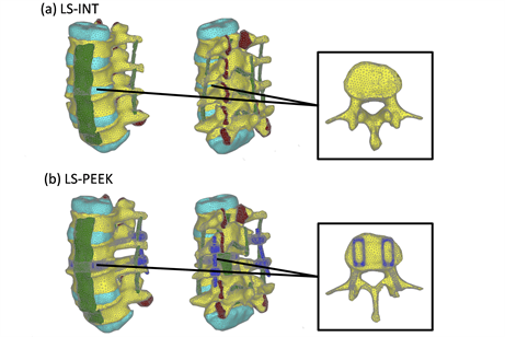
Figure 1. Finite element (FE) models. (a) LS-INT: intact FE model; (b) LS-PEEK: FE model of the spine with a polyetheretherketone (PEEK) spacer placed at the L3-4 disc using the posterior approach and posterior instrumentation (PI).
was calculated on the assumption of a linear relationship between CT value [Hounsfield unit (HU)] and ρ. Keyak’s conversion formula was used to calculate the Young’s (E) (MPa) and yield stress (σr) (MPa) of bone from ρ, as shown in the following equations [ 16 ].
(1)
(2)
(3)
Poisson’s ratio was constant at 0.4 [ 17 ], and the mechanical properties of the different tissues were obtained from previous studies [ 18 ] as shown in Table 1.
Damage analysis was performed by setting the tensile and compressive failure criteria separately. It is assumed in MF that failure of an element takes place when the stress or strain reaches its critical value. In the case of tensile stress condition, linear elastic deformation behavior was assumed, and tensile failure of the element occurred if the maximum principal stress reached the critical value [ 19 , 20 ]. In this study, 0.8σr was used as the critical value on the basis of reference 21. After the tensile failure occurred, the stiffness of the element was reset to the minimum value in the entire model. On the other hand, elastic-plastic

Table 1. Material properties of the components used in this study. Abbreviations: ALL, anterior longitudinal ligament; PLL, posterior longitudinal ligament; TL, intertransverse ligament; CL, capsular ligaments of facet joints; LF, ligamentum flavum; ISL, interspinous ligament; SSL, supraspinous ligament; PEEK, polyetheretherketone.
deformation behavior was assumed under compressive stress, and the yielding was controlled by the Drucker-Prager equivalent stress. If the average equivalent stress of an element reached the yield stress σr, then plastic deformation took place. After the occurrence of plastic deformation, compressive failure was controlled by the minimum principal strain [ 21 ]. The critical value for the minimum principal strain used in this FEA was −10,000 με. After the occurrence of compressive failure, the element stiffness was reset to the minimum value in the same way as after tensile failure.
2.3. Analysis
Loads and moments simulating actual movements of the living body were applied to both the models, LS-INT and LS-PEEK. Figure 2 shows the boundary conditions applied. To determine the state of stress prior to the occurrence of failure, static elastic analysis was performed by applying (I) 400 N compressive load and two rotational loads comprising (II) flexion and (III) extension. The Drucker-Prager equivalent stress distributions were evaluated at the cage contact surfaces on the inferior surface of L3 and the superior surface of L4 in each case. Damage analysis was also carried out to investigate damage to the bony tissue around the cages. Damage analysis was performed by applying the same boundary conditions as in (I) above, increasing the vertical load to a maximum of 3000 N. The distribution patterns of damage elements in the L2-L5 vertebral bodies and their cumulative numbers were evaluated. The equivalent plastic strain distributions on the L3 inferior surface and L4 superior surface were also examined.
3. Results
Figure 3 shows the Drucker-Prager stress distributions on the L3 inferior surface and L4 superior
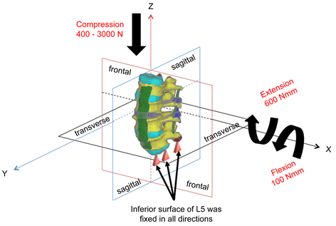
Figure 2. Loads and boundary conditions.
surface obtained from the three types of static elastic analysis. The Drucker-Prager equivalent stress on the L3 and L4 vertebral endplates was greater in LS-PEEK than in LS-INT under all loading conditions. In LS-PEEK, stress tended to concentrate around the cage contact surfaces under all conditions.
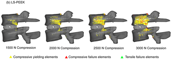
Figure 4 shows the distribution of damage elements in L3 and L4 identified by damage analysis. In LS-INT, at 2000 N compression and above, there were only a few damage elements in the center of the L3 vertebral body. In LS-PEEK, there were more damage elements along the bone around the cages in the L3 vertebral body posterior to the cage contact surfaces, followed by the area of the L4 vertebral body posterior to the cage contact surfaces. Most of the damage here was in the form of yielding and compressive failure due to compression.
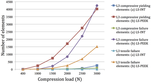
Figures 5(a) and Figure 5(b) show the cumulative numbers of damage elements in L3 and L4 identified by damage analysis. In LS-INT, at 2000 N compression and above, there was only a small increase in damage elements, and there were almost no damage elements in L4. In both vertebral bodies, the number of damage elements was clearly greater in LS-PEEK. This difference was greater at higher loads.
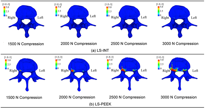
In LS-PEEK damage elements increased around the cages at the points of contact between them, and at L3 and L4, as shown in Figure 4; therefore, we analyzed the equivalent plastic strain distributions on the L3 inferior surface and L4 superior surface. Figure 6 shows these distributions at 1500 N and above, at which differences in distribution were evident. This visualized the gradual expansion of high levels of equivalent plastic strain in the inferior surface of L3 in LS-PEEK along the cages from the area posterior to them to the area anterior to them as the loading increased above 1500 N.
4. Discussion
FEA is an effective and established simulation method for the human body in biomechanical evaluations of the spine. The accurate reproduction of different mechanical properties is important for FEA-based biomechanical analysis [ 22 ]. However, bone strength varies greatly between individuals as a result of the effect of osteoporosis, and this has been difficult to reproduce. Almost all previous studies have used a two-layer model of bone material consisting of cortical bone and medulla with consistent mechanical properties for analysis [ 10 , 12 , 13 ]. In this study, we created a patient-specific FE model using bone densities derived from CT images of an individual patient, for which we determined element-specific Young’s modulus and carried out damage analysis. Although most researchers have found it difficult to establish a model for the
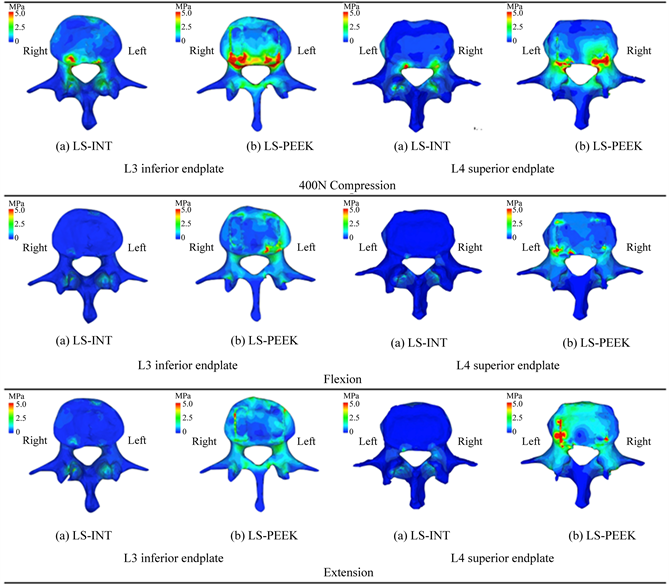
Figure 3. Drucker-Prager equivalent stress distributions on the L3 inferior endplate and L4 superior endplate under loads of 400 N and rotational loads of bending forward and backward.
ligaments around the vertebral bodies, modeling them only as spring elements exerting tension only in one dimension [ 13 , 23 ], we modeled and analyzed the ligaments around the vertebral bodies as three-dimensional finite elements in this study. To the best of our knowledge, we are the first to successfully reproduce the tension and deformation behavior around the cages used in PLIF in a simulation using the osteoporotic vertebral bodies of an old person, allowing us to predict the mechanism by which cage subsidence occurs.
In recent years, cages of various materials and shapes have been used in the attempt to prevent subsidence. The prevention of cage subsidence in PLIF has been approached from a variety of perspectives, including bone strength and cage materials and shapes [ 24 - 26 ]. However, no study has previously focused on the biomechanics of the bone around the cages.
In this study, Drucker-Prager equivalent stress in the bone around the cages was higher in LS-PEEK than in LS-INT under all conditions, and its distribution revealed that it was particularly high around the cages and posterior to the vertebral end plates (Figure 3). This provides evidence that the concentration of
 (a)
(a)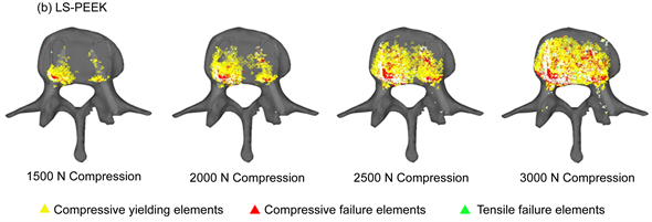 (b)
(b)
Figure 4. (a) Distribution of yielding elements and failure elements under loads of 1500 to 3000 N (entire image); (b) Distribution of yielding elements and failure elements under loads of 1500 to 3000 N (L3 inferior surface image).
Drucker-Prager equivalent stress imposes an excessive load on the vertebral body end plates, making it easy for the bony support mechanism to be lost. Our results showed that the number of damage elements in L3 and L4 was clearly higher in LS-PEEK than in LS-INT (Figure 5(a), Figure 5(b)), and that the distribution of damage elements in LS-PEEK expanded into the entire vertebral bodies from the posterior parts of the vertebral end plates (Figure 4(a), Figure 4(b)). Equivalent plastic strain, which determines plastic deformation, also expanded continuously into the entire L3 vertebral body from an area of high stress in the posterior part of the L3 vertebral end plate that was in contact with the cages (Figure 6(a), Figure 6(b)). This suggested that the sites of plastic deformation elements and equivalent plastic strain in the end plates around the cages, were in an environment conducive to cage subsidence because of the loss of bony supportive structures due to microscopic damage in the form of plastic deformation and compressive failure.
A previous cadaveric study of the distribution of bone strength in the osteoporotic vertebral end plates of a single vertebral body found that bone strength was higher on the posterolateral aspect of end plates [ 7 ]; in the present study, which modeled multiple vertebrae, the biomechanical environment in the posterior parts of the vertebral end plates was conducive to the loss of bony supportive structures. Although increased stress on the vertebral plate with cage insertion was expected, this is the first study to use FEA to describe the mechanical status of bone localized around the cages.
Preventing subsidence associated with cage insertion and obtaining good intervertebral synostosis is an important postoperative factor for PLIF. The shape of the intervertebral cage is a subject of debate
 (a)
(a)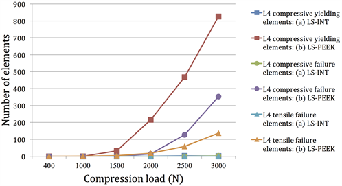 (b)
(b)
Figure 5. (a) Number of yielding elements and failure elements under loads of 1500 to 3000 N (number of elements on L3); (b) Number of yielding elements and failure elements under loads of 1500 to 3000 N (number of elements on L4).
concerning factors such as the use of cages with a large footprint to ensure biomechanical stability, on the theoretical basis that they constitute the surfaces supporting the vertebral body, or the use of cages designed in accordance with the intervertebral angle so that they fit the vertebral end plates [ 25 , 27 ]. Our results, however, predicted that cage subsidence would expand continuously from a single area of high stress. This suggested that mechanically stable cages may be those with a design that does not generate local areas of high stress, and those procedural issues, such as placing cages at sites with genuinely strong bone when inserting them between osteoporotic vertebral bodies should perhaps also be taken into consideration.
The FEA analysis used in this study had a number of limitations: 1) the loads and constraints on the vertebral bodies may differ from in vivo movement in light of the overall balance of the spine; 2) we did not take account of biological and biochemical reactions between biomaterials and bone in the synostosis
 (a)
(a)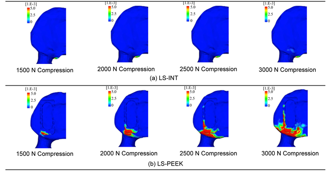 (b)
(b)
Figure 6. (a) Equivalent plastic strain distributions on the L3 inferior endplate; (b) Enlarged image of (a).
process; and 3) we also did not take account of postoperative degenerative changes to the intervertebral disks and muscles, or of the effect of fatigue due to repeated loading. Nevertheless, studies using FEA to create models from patient CT scans have been used for purposes such as assessing the pathology of osteoporosis [ 28 ] and evaluating surgical techniques [ 15 ], and this method holds great potential for application to a wide range of other clinical applications in future.
5. CONCLUSION
In this study, we used FEA in models constructed from CT images and applied computational analysis to generate damage at the element level in a patient-specific osteoporotic vertebral body to perform a biomechanical investigation of the mechanism of cage subsidence in spinal instrumentation. This analysis showed that in PLIF of osteoporotic vertebral bodies in elderly patients, the localized stress concentration generated using PEEK cages causes accumulation of microscopic damage in the weakened osteoporotic vertebral bodies around the cages, suggesting that cage subsidence may occur as a result of this damage.
References
- 1. Cloward, R.B. (1953) The Treatment of Ruptured Lumbar Intervertebral Discs by Vertebral Body Fusion. I. Indications, Operative Technique, after Care. Journal of Neurosurgery, 10, 154-168. https://doi.org/10.3171/jns.1953.10.2.0154
- 2. Brantigan, J.W., McAfee, P.C., Cunningham, B.W., Wang, H. and Orbegoso, C.M. (1994) Interbody Lumbar Fusion Using a Carbon Fiber Cage Implant versus Allograft Bone: An Investigational Study in the Spanish Goat. Spine, 19, 1436-1444. https://doi.org/10.1097/00007632-199407000-00002
- 3. Brantigan, J.W. and Steffee, A.D. (1993) A Carbon Fiber Implant to Aid Interbody Lumbar Fusion: Two-Year Clinical Results in the First 26 Patients. Spine, 18, 2106-2117. https://doi.org/10.1097/00007632-199310001-00030
- 4. Matge, G. (2002) Cervical Cages Fusion with 5 Different Implants: 250 Cases. Acta Neurochirurgica, 144, 539-549.https://doi.org/10.1007/s00701-002-0939-0
- 5. Ray, C.D. (1997) Threaded Titanium Cages for Lumbar Interbody Fusions. Spine, 22, 667-679.https://doi.org/10.1097/00007632-199703150-00019
- 6. Steffen, T., Tsantrizos, A., Fruth, I. and Aebi, M. (2000) Cages: Designs and Concepts. European Spine Journal, 9, S89-S94. https://doi.org/10.1007/PL00010027
- 7. Hou, Y. and Yuan, W. (2012) Influences of Disc Degeneration and Bone Mineral Density on the Structural Properties of Lumbar End Plates. The Spine Journal, 12, 249-256. https://doi.org/10.1016/j.spinee.2012.01.021
- 8. Jost, B., Cripton, PA., Lund, T., Oxland, T.R., Lippuner, K., Jaeger, P. and Nolte, L.P. (1998) Compressive Strength of Interbody Cages in the Lumbar Spine: The Effect of Cage Shape, Posterior Instrumentation and Bone Density. European Spine Journal, 7, 132-141. https://doi.org/10.1007/s005860050043
- 9. Wang, Z., Fu, S., Wu, Z.X., Zhang, Y. and Lei, W. (2013) Ti2448 Pedicle Screw System Augmentation for Posterior Lumbar Interbody Fusion. Spine, 38, 2008-2015. https://doi.org/10.1097/BRS.0b013e3182a76fec
- 10. Vadapalli, S., Sairyo, K., Goel, V.K., Robon, M., Biyani, A., Khandha, A. and Ebraheim, N.A. (2006) Biomechanical Rationale for Using Polyetheretherketone (PEEK) Spacers for Lumbar Interbody Fusion—A Finite Element Study. Spine, 31, E992-E998. https://doi.org/10.1097/01.brs.0000250177.84168.ba
- 11. Xiao, Z., Wang, L., Gong, H. and Zhu, D. (2012) Biomechanical Evaluation of Three Surgical Scenarios of Posterior Lumbar Interbody Fusion by Finite Element Analysis. Biomed Eng Online, 11, 31. https://doi.org/10.1186/1475-925X-11-31
- 12. Liu, X., Ma, J., Park, P., Huang, X., Xie, N. and Ye, X. (2017) Biomechanical Comparison of Multilevel Lateral Interbody Fusion with and without Supplementary Instrumentation: A Three-Dimensional Finite Element Study. BMC Musculoskeletal Disorders, 18, 63. https://doi.org/10.1186/s12891-017-1387-6
- 13. Alapan, Y., Demir, C., Kaner, T., Guclu, R. and Inceoglu, S. (2013) Instantaneous Center of Rotation Behavior of the Lumbar Spine with Ligament Failure. Journal of Neurosurgery: Spine, 18, 617-626. https://doi.org/10.3171/2013.3.SPINE12923
- 14. Mazlan, M.H., Todo, M., Takano, H. and Yonezawa, I. (2016) Effect of Cage Insertion Orientation on Stress Profiles and Subsidence Phenomenon in Posterior Lumbar Interbody Fusion. Journal of Medical and Bioengineering, 5, 93-97.
- 15. Matsuura, Y., Giambini, H., Ogawa, Y., Fang, Z., Thoreson, A.R., Yaszemski, M.J., Lu, L. and An, K.N. (2014) Specimen-Specific Nonlinear Finite Element Modeling to Predict Vertebrae Fracture Loads after Vertebroplasty. Spine, 39, E1291-E1296. https://doi.org/10.1097/BRS.0000000000000540
- 16. Keyak, J.H., Meagher, J.M., Skinner, H.B. and Mote, C.D. (1990) Automated Three-Dimensional Finite Element Modelling of Bone: A New Method. Journal of Biomedical Engineering, 12, 389-397.
- 17. Keyak, J.H., Rossi, S.A., Jones, K.A. and Skinner, H.B. (1998) Prediction of Femoral Fracture Load using Automated Finite Element Modeling. Journal of Biomechanics, 31, 125-133.
- 18. Tsuang, Y.H., Chiang, Y.F., Hung, C.Y., Wei, H.W., Huang, C.H. and Cheng, C.K. (2009) Comparison of Cage Application Modality in Posterior Lumbar Interbody Fusion with Posterior Instrumentation—A Finite Element Study. Medical Engineering & Physics, 31, 565-570.
- 19. Kaneko, T.S., Pejcic, M.R., Tehranzadeh, J. and Keyak, J.H. (2003) Relationships between Material Properties and CT Scan Data of Cortical Bone with and without Metastatic Lesions. Medical Engineering & Physics, 25, 445-454.
- 20. Keaveny, T.M., Wachtel, E.F., Ford, C.M. and Hayes, W.C. (1994) Differences between the Tensile and Compressive Strengths of Bovine Tibial Trabecular Bone Depend on Modulus. Journal of Biomechanics, 27, 1137-1146.
- 21. Bessho, M., Ohnishi, I., Matsuyama, J., Matsumoto, T., Imai, K. and Nakamura, K. (2007) Prediction of Strength and Strain of the Proximal Femur by a CT-Based Finite Element Method. Journal of Biomechanics, 40, 1745-1753.
- 22. Kurtz, S.M. and Devine, J.N. (2007) PEEK Biomaterials in Trauma, Orthopedic, and Spinal Implants. Biomaterials, 28, 4845-4869.
- 23. Chen, S.H., Lin, S.C., Tsai, W.C., Wang, C.W. and Chao, S.H. (2012) Biomechanical Comparison of Unilateral and Bilateral Pedicle Screws Fixation for Transforaminal Lumbar Interbody Fusion after Decompressive Surgery—A Finite Element Analysis. BMC Musculoskeletal Disorders, 16, 72. https://doi.org/10.1186/1471-2474-13-72
- 24. Oh, K.W., Lee, J.H., Lee, D.Y. and Shim, H.J. (2017) The Correlation between Cage Subsidence, Bone Mineral Density, and Clinical Results in Posterior Lumbar Interbody Fusion. Clinical Spine Surgery, 30, E683-E689.
- 25. Lang, G., Navarro-Ramirez, R., Gandevia, L., Hussain, I., Nakhla, J., Zubkov, M. and Härtl, R. (2017) Elimination of Subsidence with 26-Mm-Wide Cages in Extreme Lateral Interbody Fusion. World Neurosurgery, 104, 644-652.
- 26. Korovessis, P., Repantis, T., Baikousis, A. and Iliopoulos, P. (2012) Posterolateral versus Circumferential Instrumented Fusion for Monosegmental Lumbar Degenerative Disc Disease using an Expandable Cage. European Journal of Orthopaedic Surgery & Traumatology, 22, 639-645. https://doi.org/10.1007/s00590-011-0890-y
- 27. Lee, J.H., Lee, D.O., Lee, J.H. and Shim, H.J. (2015) Effects of Lordotic Angle of a Cage on Sagittal Alignment and Clinical Outcome in One Level Posterior Lumbar Interbody Fusion with Pedicle Screw Fixation. BioMed Research International, 2015, Article ID: 523728. https://doi.org/10.1155/2015/523728
- 28. Tawara, D., Sakamoto, J., Murakami, H., Kawahara, N., Oda, J. and Tomita, K. (2010) Mechanical Therapeutic Effects in Osteoporotic L1-Vertebrae Evaluated by Nonlinear Patient-Specific Finite Element Analysis. Journal of Biomechanical Science and Engineering, 5, 499-514. https://doi.org/10.1299/jbse.5.499
- 29. Cloward, R.B. (1953) The Treatment of Ruptured Lumbar Intervertebral Discs by Vertebral Body Fusion. I. Indications, Operative Technique, after Care. Journal of Neurosurgery, 10, 154-168. https://doi.org/10.3171/jns.1953.10.2.0154
- 30. Brantigan, J.W., McAfee, P.C., Cunningham, B.W., Wang, H. and Orbegoso, C.M. (1994) Interbody Lumbar Fusion Using a Carbon Fiber Cage Implant versus Allograft Bone: An Investigational Study in the Spanish Goat. Spine, 19, 1436-1444. https://doi.org/10.1097/00007632-199407000-00002
- 31. Brantigan, J.W. and Steffee, A.D. (1993) A Carbon Fiber Implant to Aid Interbody Lumbar Fusion: Two-Year Clinical Results in the First 26 Patients. Spine, 18, 2106-2117. https://doi.org/10.1097/00007632-199310001-00030
- 32. Matge, G. (2002) Cervical Cages Fusion with 5 Different Implants: 250 Cases. Acta Neurochirurgica, 144, 539-549.https://doi.org/10.1007/s00701-002-0939-0
- 33. Ray, C.D. (1997) Threaded Titanium Cages for Lumbar Interbody Fusions. Spine, 22, 667-679.https://doi.org/10.1097/00007632-199703150-00019
- 34. Steffen, T., Tsantrizos, A., Fruth, I. and Aebi, M. (2000) Cages: Designs and Concepts. European Spine Journal, 9, S89-S94. https://doi.org/10.1007/PL00010027
- 35. Hou, Y. and Yuan, W. (2012) Influences of Disc Degeneration and Bone Mineral Density on the Structural Properties of Lumbar End Plates. The Spine Journal, 12, 249-256. https://doi.org/10.1016/j.spinee.2012.01.021
- 36. Jost, B., Cripton, PA., Lund, T., Oxland, T.R., Lippuner, K., Jaeger, P. and Nolte, L.P. (1998) Compressive Strength of Interbody Cages in the Lumbar Spine: The Effect of Cage Shape, Posterior Instrumentation and Bone Density. European Spine Journal, 7, 132-141. https://doi.org/10.1007/s005860050043
- 37. Wang, Z., Fu, S., Wu, Z.X., Zhang, Y. and Lei, W. (2013) Ti2448 Pedicle Screw System Augmentation for Posterior Lumbar Interbody Fusion. Spine, 38, 2008-2015. https://doi.org/10.1097/BRS.0b013e3182a76fec
- 38. Vadapalli, S., Sairyo, K., Goel, V.K., Robon, M., Biyani, A., Khandha, A. and Ebraheim, N.A. (2006) Biomechanical Rationale for Using Polyetheretherketone (PEEK) Spacers for Lumbar Interbody Fusion—A Finite Element Study. Spine, 31, E992-E998. https://doi.org/10.1097/01.brs.0000250177.84168.ba
- 39. Xiao, Z., Wang, L., Gong, H. and Zhu, D. (2012) Biomechanical Evaluation of Three Surgical Scenarios of Posterior Lumbar Interbody Fusion by Finite Element Analysis. Biomed Eng Online, 11, 31. https://doi.org/10.1186/1475-925X-11-31
- 40. Liu, X., Ma, J., Park, P., Huang, X., Xie, N. and Ye, X. (2017) Biomechanical Comparison of Multilevel Lateral Interbody Fusion with and without Supplementary Instrumentation: A Three-Dimensional Finite Element Study. BMC Musculoskeletal Disorders, 18, 63. https://doi.org/10.1186/s12891-017-1387-6
- 41. Alapan, Y., Demir, C., Kaner, T., Guclu, R. and Inceoglu, S. (2013) Instantaneous Center of Rotation Behavior of the Lumbar Spine with Ligament Failure. Journal of Neurosurgery: Spine, 18, 617-626. https://doi.org/10.3171/2013.3.SPINE12923
- 42. Mazlan, M.H., Todo, M., Takano, H. and Yonezawa, I. (2016) Effect of Cage Insertion Orientation on Stress Profiles and Subsidence Phenomenon in Posterior Lumbar Interbody Fusion. Journal of Medical and Bioengineering, 5, 93-97.
- 43. Matsuura, Y., Giambini, H., Ogawa, Y., Fang, Z., Thoreson, A.R., Yaszemski, M.J., Lu, L. and An, K.N. (2014) Specimen-Specific Nonlinear Finite Element Modeling to Predict Vertebrae Fracture Loads after Vertebroplasty. Spine, 39, E1291-E1296. https://doi.org/10.1097/BRS.0000000000000540
- 44. Keyak, J.H., Meagher, J.M., Skinner, H.B. and Mote, C.D. (1990) Automated Three-Dimensional Finite Element Modelling of Bone: A New Method. Journal of Biomedical Engineering, 12, 389-397.
- 45. Keyak, J.H., Rossi, S.A., Jones, K.A. and Skinner, H.B. (1998) Prediction of Femoral Fracture Load using Automated Finite Element Modeling. Journal of Biomechanics, 31, 125-133.
- 46. Tsuang, Y.H., Chiang, Y.F., Hung, C.Y., Wei, H.W., Huang, C.H. and Cheng, C.K. (2009) Comparison of Cage Application Modality in Posterior Lumbar Interbody Fusion with Posterior Instrumentation—A Finite Element Study. Medical Engineering & Physics, 31, 565-570.
- 47. Kaneko, T.S., Pejcic, M.R., Tehranzadeh, J. and Keyak, J.H. (2003) Relationships between Material Properties and CT Scan Data of Cortical Bone with and without Metastatic Lesions. Medical Engineering & Physics, 25, 445-454.
- 48. Keaveny, T.M., Wachtel, E.F., Ford, C.M. and Hayes, W.C. (1994) Differences between the Tensile and Compressive Strengths of Bovine Tibial Trabecular Bone Depend on Modulus. Journal of Biomechanics, 27, 1137-1146.
- 49. Bessho, M., Ohnishi, I., Matsuyama, J., Matsumoto, T., Imai, K. and Nakamura, K. (2007) Prediction of Strength and Strain of the Proximal Femur by a CT-Based Finite Element Method. Journal of Biomechanics, 40, 1745-1753.
- 50. Kurtz, S.M. and Devine, J.N. (2007) PEEK Biomaterials in Trauma, Orthopedic, and Spinal Implants. Biomaterials, 28, 4845-4869.
- 51. Chen, S.H., Lin, S.C., Tsai, W.C., Wang, C.W. and Chao, S.H. (2012) Biomechanical Comparison of Unilateral and Bilateral Pedicle Screws Fixation for Transforaminal Lumbar Interbody Fusion after Decompressive Surgery—A Finite Element Analysis. BMC Musculoskeletal Disorders, 16, 72. https://doi.org/10.1186/1471-2474-13-72
- 52. Oh, K.W., Lee, J.H., Lee, D.Y. and Shim, H.J. (2017) The Correlation between Cage Subsidence, Bone Mineral Density, and Clinical Results in Posterior Lumbar Interbody Fusion. Clinical Spine Surgery, 30, E683-E689.
- 53. Lang, G., Navarro-Ramirez, R., Gandevia, L., Hussain, I., Nakhla, J., Zubkov, M. and Härtl, R. (2017) Elimination of Subsidence with 26-Mm-Wide Cages in Extreme Lateral Interbody Fusion. World Neurosurgery, 104, 644-652.
- 54. Korovessis, P., Repantis, T., Baikousis, A. and Iliopoulos, P. (2012) Posterolateral versus Circumferential Instrumented Fusion for Monosegmental Lumbar Degenerative Disc Disease using an Expandable Cage. European Journal of Orthopaedic Surgery & Traumatology, 22, 639-645. https://doi.org/10.1007/s00590-011-0890-y
- 55. Lee, J.H., Lee, D.O., Lee, J.H. and Shim, H.J. (2015) Effects of Lordotic Angle of a Cage on Sagittal Alignment and Clinical Outcome in One Level Posterior Lumbar Interbody Fusion with Pedicle Screw Fixation. BioMed Research International, 2015, Article ID: 523728. https://doi.org/10.1155/2015/523728
- 56. Tawara, D., Sakamoto, J., Murakami, H., Kawahara, N., Oda, J. and Tomita, K. (2010) Mechanical Therapeutic Effects in Osteoporotic L1-Vertebrae Evaluated by Nonlinear Patient-Specific Finite Element Analysis. Journal of Biomechanical Science and Engineering, 5, 499-514. https://doi.org/10.1299/jbse.5.499