Positioning
Vol.2 No.2(2011), Article ID:5051,13 pages DOI:10.4236/pos.2011.22007
Machine Perception Through Natural Intelligence
![]()
Verchratskogo st. 15-1, Lviv 79010 Ukraine
Email: sklyar@tsp.lviv.ua
Received December 30th , 2010; revised March 1st , 2011; accepted April 20th, 2011.
Keywords: Magnetic Field, Induction Sensor, SuFET, Nerve Impulses, Interface, Gradiometer, Sensing Area
ABSTRACT
The sensing organs are exponentially better than any of analogous artificial ones. That is why using them in full scale is a perspective trend to the efficient (advanced) machine perception. On the other hand, limitations of sensing organs could be replaced by the perfect artificial ones with the subsequent training the nervous system on their output signals. An attempt to lay down the foundations of biosensing by natural sensors and in addition to them by the artificial transducers of physical quantities, also with their expansion into space arrays and external/implantable functioning in relation to the nervous system is performed. The advances in nanotechnology are opening the way to achieving direct electrical contact of nanoelectronic structures with electrically and electrochemically active neurocellular structures. The transmission of the sensors’ signals to a processing unit has been maintaining by an electromagnetic transistor/memristor (externally) and superconducting transducer of ionic currents (implantable). The arrays of the advanced sensors give us information about the space and direction dynamics of the signals' spreading.The measuring method and necessary performance data of the sensor for the robot’s orientation in the ambient magnetic field with living being-machine interaction in order to obtain input and output signals from brain and motor nerves to the measurement system and vice versa are introduced. The range of applied sensors differs from an induction sensor to superconducting induction magnetometer. The analytical expressions for arrangements of the head sensors in differential and vector (3D) relative positions are deduced. Sensitivity of the perception method makes it possible to recognize the linear translation of 10−2 m and disposal in space of 10−3 m3. Interaction between living beings and robotic equipment is given analytical treatment.
1. Introduction. Artificial Sensors with the Human Machine Interface
Electronic Nose is a smart instrument that is designed to detect and discriminate among complex odours using an array of sensors. The array of sensors consists of a number of broadly tuned (non-specific) sensors that are treated with a variety of odour-sensitive biological or chemical materials [1].
This instrument provides a rapid, simple and non- invasive sampling technique, for the detection and identification of a range of volatile compounds. The key function of an electronic nose is to mimic human olfactory system. Typically an electronic nose consists of three elements: a sensor array which is exposed to the volatiles, conversion of the sensor signals to a readable format and software analysis of the data to produce characteristic outputs related to the odour encountered. The main parts of a typical biosensor are shown in Figure 1.
The artificial tactile sensor integrates a micro electro-mechanical system (MEMS) array having a number of sensing elements (16 channels in about 20 mm2) similar to the innervation density of mechanoreceptors in the hand (about 1 unit/ mm2). The technological approach is based on a 3D MEMS core unit with a soft and compliant packaging. The microsensor can be integrated with a packaging architecture resulting in a robust and compliant tactile sensor for application in artificial hands, while sensitive enough to detect slip events, showing that silicon based tactile sensors can go beyond laboratory practice [2]. The tactile sensor array, depicted in Figure 2, had 16 channels as total tactile sensor outputs.
The measurement of magnetic fields (MFs) is an important task for the majority of autonomous missions. The distribution of permanent and the value of periodical MFs give the data about placement of ferromagnetic objects and sources of EM radiation respectively. On the other hand, these signals will be a reference point and guiding line for a walking robot (Figure 3).
Detection of some magnetic anomalies of the Earth’s MF and their variations is provided by fluxgate sensors
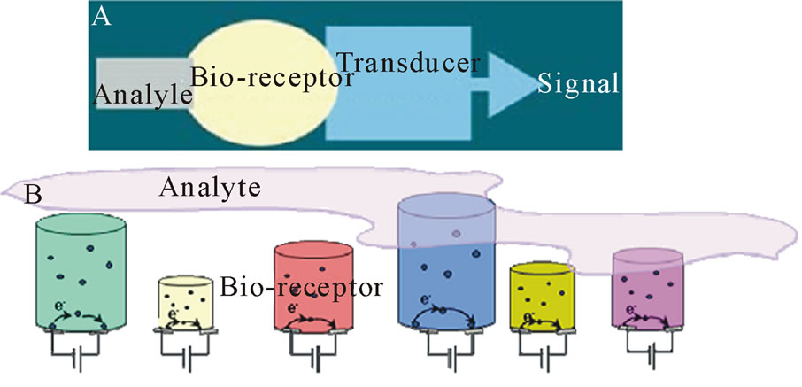
Figure 1. (A) The main parts of a typical biosensor, (B) A sensor array, each polymer changes its size and therefore its resistance, by a different amount and making a pattern of the change. Copyright 2009 IFSA.

Figure 2 (a) 3D design of the tactile sensor array. (b) Top: the 2 × 2 MEMS array compared with human finger; bottom: a FIB image of the MEMS sensor. (c) Top view of the sensor array. Copyright 2008 IEEE.
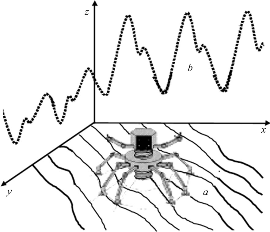
Figure 3 The walking robot in MF environment. a) x-y plane defines the varying DC natural MF; b) around z axis spreads AC industrial MF interference.
[3]. When the spectrum of EM signals in the environment lies in a wide frequency range (10 Hz - 500 kHz), the application of highly-sensitive induction sensors (ISs) is necessary. The application of a low-Tc SQUID device is able to embrace both of the said frequency ranges with maximum sensitivity. It is made of non-magnetic material and the principle of operation is to detect two magnetic signals at different distances from the source and arrange for them to be in opposition around a local supercooled circuit. This ‘gradiometer’ approach eliminates most of the noise—caused by spurious MFs originating from, for example, electrical devices or natural (geomagnetic sources. A typical unshielded laboratory has a noise level in the 0 - 10 Hz frequency region of about 10−7 T and geomagnetic noise in the same frequency range is of the order of 10−10 T. Any small field changes the direction of the MF vector in the space and this produces a distortion in the waveform of the signal in the detection coils. The very expensive use of the SQUID magnetometer up until now has produced many advances in the understanding of MFs from weak sources. The advance of much cheaper room—temperature sensor technologies offers the prospect of much greater use of MF monitoring [4]. As a general rule, scientific instrumentation should impact mass constraints as little as possible; however, robot-mounted instruments in particular must be lightweight to survive deployment under highstress conditions when used in connection with spacecraft or underwater. This weight constraint can limit both the size of the sensor and its placement on moving part. Also, autonomous systems require minimal consumption power. Both factors translate into severe constraints on the capability of the instrument to measure weak EMFs encountered in the environment. In addition, outer space and underwater conditions require endurance against variations in the wide range of temperature, humidity, and atmospheric pressure.
The human machine interface using electromyjogram (EMG) signal to artificially control the limb movement. Each muscle fiber has a potential and motor unit action potential generated by construction of muscle is studied and corresponding actuation is provided to robotics arm. In this system a relatively more flexible and robust communication technique generates commands from EMG signals (Figure 4). Such an autonomous mobile humanoid robot will be able to assist in a workshop environment and interact with a human [5]. Three aspects to reach this target are considered. First, how the brain of the exoskeleton robot is constructed to be able to manipulate objects like humans do. Second exploration of appropriate binominals that can be used as an actuating quantity to move the Robotic arm; and finally how programming of manipulation tasks is realized.
Implantable neural probes are generally preferred to have a minimum footprint as possible to minimize neural damage and to facilitate easy entry and movement through the brain tissue. Polymeric microprobes have received a great deal of attention owing to their simple fabrication process, flexibility and biocompatibility. Implantable neural probes for neuroscience and brain machine interfaces are generally preferred to have a minimum footprint as possible to minimize neural damage [6]. A conceptual representation of the multichip recording interface is shown in Figure 5. The device handles 16 neural recording channels as a proof of concept [7].
Alternatively, a superconducting field-effect transistor (SuFET) based neurotransducer (SuFETTr) with carbon nanotubes (CNT) or pickup coil (PC) kind of input circuit for the nerve and neuronic impulse has been designed [8]. A nanoSuFET with a high-temperature superconducting channel is introduced into the nerve fibre or brain tissue for transducing their signals in both directions. As a result, we have achieved SuFETTr that is suitable for ascertaining the variety of values [9]. Two directions of SuFETTr function enable decoding of these signals by comparing the result of its reaction on some process or organ with an action on them of the simulated electrical or biochemical signal after their reverse transducing through the SuFETTr(s). Moreover, a number of the relevant measuring devices, as an intermediate element between physical value and the nerve system, are designed on its basis [10].
2. Signal Processing in the Biointerfaces
Magnetocardiography (MCG) is a noninvasive method of detecting the cardiac magnetic fields above the body surface using DC SQUIDs. MCG has the potential to detect arrhythmia and ischemia with a lower level of adverse effects than electrocardiograms. Also most SQUIDs are incorporated into whole-head systems for magnetoencephalography (MEG) - the detection of MFs produced by brain. A typical helmet contains about 300 sensors, including a number of reference sensors for noise cancellation, cooled to 4.2 K. [11]
A current trend in such diagnostics are portable and wearable magnetometer systems which have, in the same time, high signal processing and signal-to-noise ratio parameter data characteristics. Simultaneous amplification of the piking up MCG & MEG neurosignals by an on-site magnetic flow has been implemented. Matrix of the sensing micro-nanoPCs are distributed under the heart or brain surface with temperature of the body [12].
Implantable neural probes are generally preferred to have a minimum footprint as possible to minimize neural damage and to facilitate easy entry and movement through the brain tissue. Polymeric microprobes have received a great deal of attention owing to their simple fabrication process, flexibility and biocompatibility. Implantable neural probes for neuroscience and brain machine interfaces are generally preferred to have a minimum footprint as possible to minimize neural damage [13].
The concept of an implantable wireless platform, without any percutaneous skin-puncturing elements, demands the implementation of a heterogeneous, active microelectronics platform. At a minimum, the implanted “microsystem” requires in-situ integration of ultralow-power microelectronic ASICs with the cortical microelectrode neural probes, and must provide broadband telemetry and a means to deliver power wirelessly to the active implanted components [14].
A 16-channel version of a fully implantable microsystem has been implemented and tested on the benchtop and used in initial animal tests. This microsystem is a single-unit construct (Figure 6) where analog and digital chips are integrated on a flexible substrate together with a low threshold, infrared semiconductor diode laser to transmit the digitized neural signals through the skin. Power and clocking are delivered to the system via inductive coupling, but the system can also be configured to be powered optically using a high efficiency photovoltaic energy converter.
By implementing CMOS technology for neural imaging, not only is imaging in multiple modalities possible, electrical stimulation and sensing can be integrated onto a single device, thereby resulting in a highly compact and miniaturized tool for the study of the brain (Figure 7) [15].
Improvement in the packaging process has resulted in

Figure 4. EMG has HF content (up to 250 Hz). Copyright 2008 IFSA.
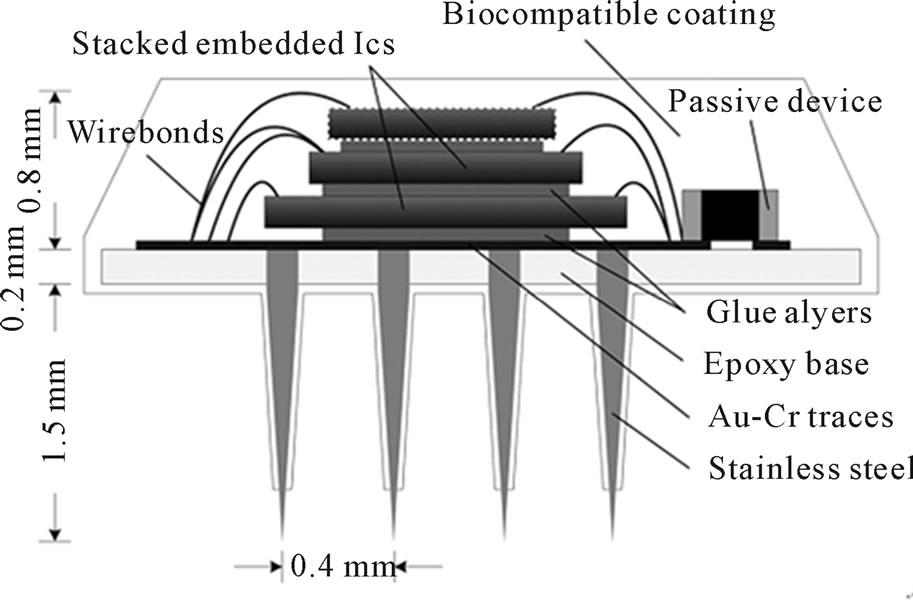
Figure 5. Conceptual representation of the multichip neural interface. the ICs implementing the active part are stacked and bonded on the base of a micromachined stainless-steel microelectrodes array. Copyright 2009 IEEE.
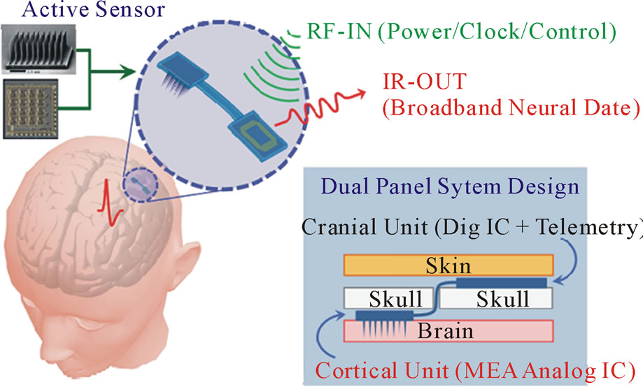
Figure 6. Schematics of the ‘dual panel’ brain implantable microsystem featuring an active brain sensor (microelectrode array integrated to amplifier IC) in the cortical unit, and hybrid A/D, control, and RF-IR (Infrared) telemetry in the cranial unit. Copyright 2009 IEEE.
a compact single-chip device for minimally invasive imaging inside the mouse brain. observation. Furthermore, it was found that the brain continued to function normally and respond to external stimulus, both chemical and electrical, while the device was embedded inside the brain. Figure 8 shows typical recordings with and without the device inserted in the brain.
Brain Communication Interface (BCI) is an umbrella term for the technology in which the motor behavior decoded from neural activity in real-time is used to control an external electro-mechanical device. The forces and position can be predicted simultaneously without any degradation in decoding quality. Various important features of the approach and issues are raised by its implementation [16].
Once the Digital Signal controller (DSC) is finalized an appropriate sensor would be selected to pick the biological data. A hardware system then needs to be developed to amplify and filter the biological signal picked [17]. The analog output of this amplifier system is then converted into a digital output using ADC so that it can be interfaced with the host computer that acts as the output display device. Designs however now make it possible to interface analog data directly to the computer. Data control and signal processing algorithms are then explored on the acquired signal.
Block diagram of the Digital Signal Processor based real time embedded system for acquisition of Human
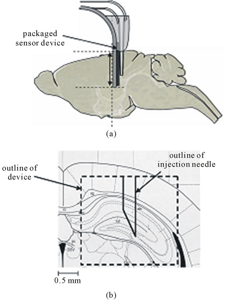
Figure 7. Position of the device inside the mouse brain during imaging showing. (a) The sagittal plane view. (b) Coronal plane view. Copyright 2008 IEEE.
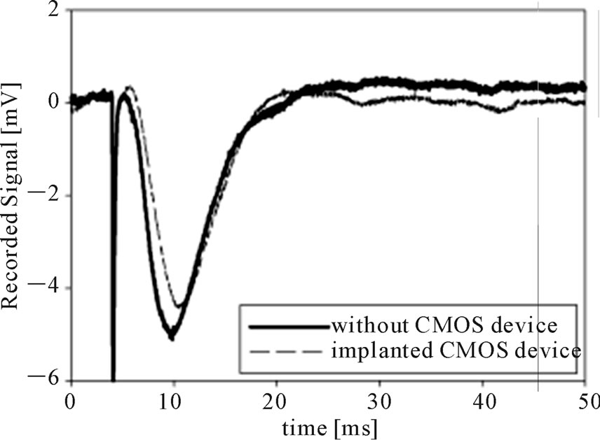
Figure 8. Typical electrophysiological recordings with and without the implanted CMOS device. Copyright 2008 IEEE.
Physiological Signals is sketched in Figure 9. The measurement system consists of a transducer to pick the human physiological signal, amplifier system, hardware band-pass filter, fifty hertz notch filter, DSC and a personal computer as the output display device.
An example of further processing of the sensing signals is analogous to the combination of heart rate and body position information recorded or monitored simultaneously can provide a valuable set of physiological and behavioral data related to the physical activity and cardiac activity. The added knowledge of the subject’s body position and activity intensity provides very valuable information and creates a history for monitoring, diagnostics, or health alerts. A discrete and minimally obtrusive wearable device allowing synchronous measurement of these physiological parameters can further offer enhanced mobility, for the very first time, to the collection and monitoring of these datasets for both research and practical applications [18].
The acceleration and bio-potential signals taken from the multi-functional sensor are first amplified through a custom signal conditioning circuit. The resulting signals are then inputted into the analog-digital converter (ADC) used to digitize the output signals. Figure 10 shows an overview diagram of the accelerometer data collection and processing system. This prototype device is able to detect different body positions such as standing, sitting, and lying on different sides of the body. It also processes motion sensor data by calculating the variance of the sample data, in order to determine movement intensity.
3. IS as the Organ of Sixth Feeling
Taking into account the said restrictions, it is undesirable to use in the robot a fluxgate sensor due to its active type of action. Also is impossible to exploit a SQUID device since it needs a liquid helium container. SQUID systems being almost ideal for the detection of very small amounts of flux from small samples, but less well-suited to the detection of low flux densities (i.e. where very low MFs are encountered). The high coil inductance of the induction system, on the other hand, can couple to a large quantity of flux [19]. It appears that these difficulties frequently reduce, in principle, the performance of SQUID magnetometers to a level below that demonstrated in this article, using an ambient-temperature induction system. This IS is also compact, robust, operates at room temperature, exhibits a wide dynamic range, and may be easily integrated into differential or multiple sensor gradiometric configurations which are feasible in a multi-limb walking robot.
A new method to assess a body inclination/azimuth using 3-D Earth’s MF sensor, even in dynamic conditions was proposed [19]. Indeed, a magnetometer is insensitive to acceleration while responding to a change of orientation in the 3-D space. However, in the general case, a 3-D magnetometer is not sufficient to track a 3-D orientation. Magnetometers are more commonly employed to either determine a compass heading information or to compensate a rate gyroscope integration drift.
The main point is that by restricting ourselves to particular movements with one or two degrees of freedom (DOFs), a magnetometer is sufficient to estimate 2 DOFs: the movement is constrained in one plane which can rotate around one fixed (or not) axis. For example, during walking, we can be interested in rotations in the saggital plane (e.g., knee flexion/extension) and azimuth direction of walk. Although limited to two DOFs, it is important to note that we can address a movement in 3-D space. Figure 11 presents the different normalized accelerations measured in the sensor frame: the calibrated measured acceleration : dark solid line, the predicted gravitational component
 : dotted line, and the computed kinematical component
 : light solid curve.
3.1. Placing of the PCs on the Limbs
PC of a walking robot is connected in parallel with the drain of a SuFET cryogenic device or an ordinary OA which are placed in the body. A PC realizing the oscillatory−forward movement along both AC industrial interferences and quasi-DC natural (Earth) environmental MFs. These fields are distributed on a surface and in space roughly according to Figure 3. The movement in quasi-DC MF HDC with the defined speed v and oscillating frequency ω with a magnitude Δα gives e.m.f. from PC:
 (1)
(1)
where S=µeff π d2 N/4 with µ0- the permeability of free space, µ0=4π·10-7 henry/meter; µeff- the effective relative permeability of a high-µ metal core; dthe average diameter of a PC; N-total turn number of the solenoid; α-
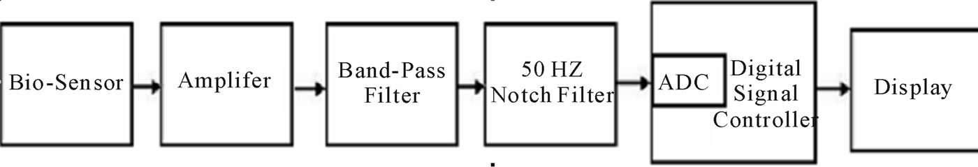
Figure 9. Block diagram of DSP based real time embedded system for acquisition of bio-signals. Copyright 2009 IFSA.
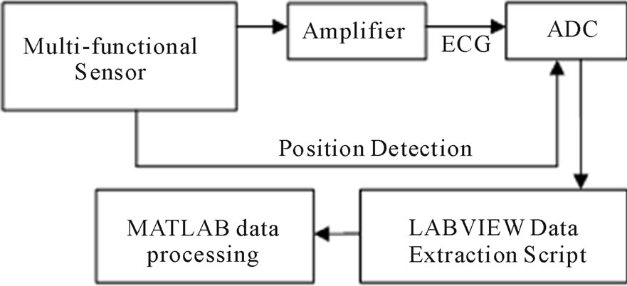
Figure 10. Sensor data extraction setup. Copyright 2007 IEEE.
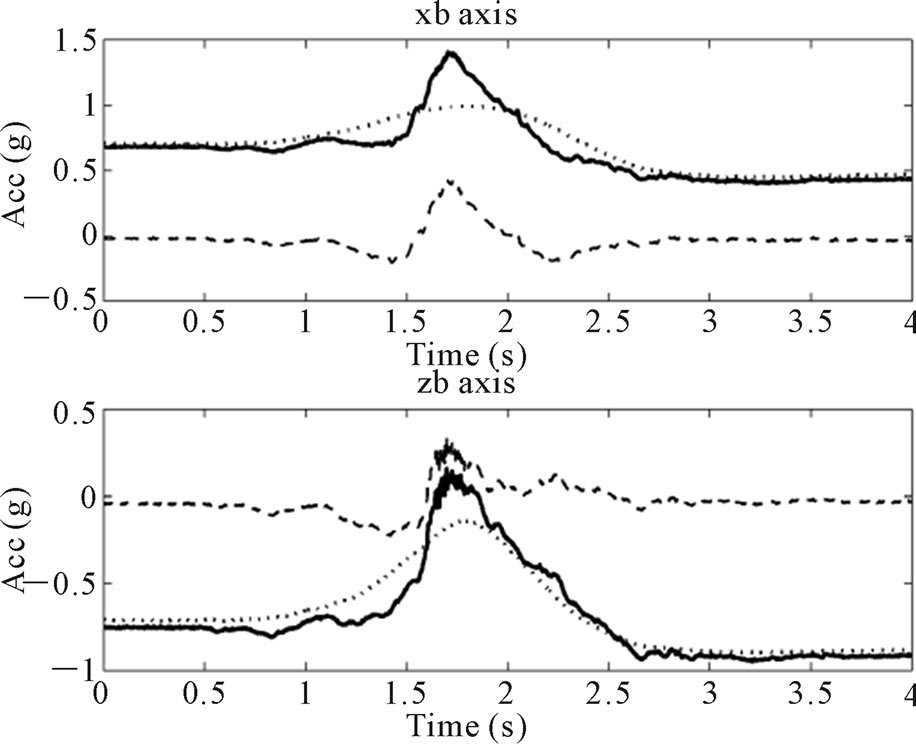
Figure 11. Separation of the gravitational and kinematical components in body frame. Accelerations during a sitto-stand transition: measured acceleration (solid line), predicted gravitational component (dotted line), and computed kinematical component (dashed line). xb-axis (top) denotes the craniocaudal axis, pointing upward; zb-axis (bottom) is the anteroposterior axis, pointing forward. Copyright 2007 IEEE.
an angle between PC’s magnetic axis and the vector of HDC. Further the amplifying/processing circuit depends on the measuring conditions and can vary from the simplest of the ordinary IS modifications to the superconducting one [21].
1) The design of the MF transducer
Some combined device, that includes all the best features of the said MF sensors/transducers seems to be the prefered trend for further development as a perception organ [21]. The SuFET is implemented into a wide-band IS device in order to acquire the sensitivity threshold below 1fT/√Hz in the frequency range from small values of Hertz to tens of MHz (0.1 Hz - 107 Hz). The proposed superconducting induction magnetometer (SIM) circuit consists of both a room-temperature or a cooled (up to superconductive) PC and a SuFET. Moreover, it gives the opportunity of repudiating both windings and electronics of feedback loops that are used in the known magnetometers. Magnetic induction BPC of AC MF with the frequency ωlimb of limbs' oscillations produce an e.m.f. in PC:
 (2)
(2)
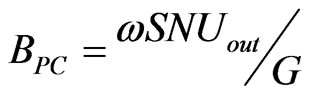
where Sa cross-section of PC, Nits number of turns. All AC MFs with the frequencies ω, high than ωlimb can be rejected by the passive HF filter [22].On the other hand, the value of EPC can be determined from the output voltage Uout of the specific kind of IS [21] with its known transfer function G according to the formula:
 (3)
(3)
As a result, an output signal receiving spontaneously, during two-dimensional travel of a walking robot in a quasi-DC MF. Moreover, by picking up the signals from both horizontal and vertical parts of the limbs, the robot derives its’ directional information from the axial course of the field lines and their inclination (defined as the angle between the direction of the field lines and the horizontal) in space. Executing the oscillations of PC with parameters (number of turns N = 2⋅104 and a cross- section area S = π⋅10−4 m2) [13] in the earth MF B0 = 50 mkT [23] with the frequency 2 Hz and α = 30˚, Δα = 30˚ arouse e.m.f. with a magnitude 50 mV according to Equation. 1. This e.m.f. will be on average equal to 5 mkV for the possible variations of the said MF with magnitude 1 - 10 nT. With these data it is possible to calculate the value of Uout for all the known five of ISs [13] with given parameters of their electrical circuit. So then (see Table 1 and Figure 4): a) for the basic transducer's variant with PC's resistance R = 2.4 kOhm, inductance L = 30 H and capacitance C = 50 pF the values of Uout shown in the second column of Table 1; b) the voltage feedback resistance Rfb = 27 kOhm is introduced into the circuit; c) the magnetic flux feedback turns Nfb = 1000 are introduced into the device; d) for SuFET the constant partial of gate voltage equal to 0.1 V and ωT, which closely relates to the small signal transconductance, are defined [13].
3.2. Using an Ambient DC and AC MFs for Robot’s Perception
An output signal of the sensor will be involved into the differential (gradiometric) operation between the robot’s limbs. After envelope detection of the quantity Uout, can be presented by changing the corresponding quasi-DC MF by the robot’s movement as defined in Figure 12. In
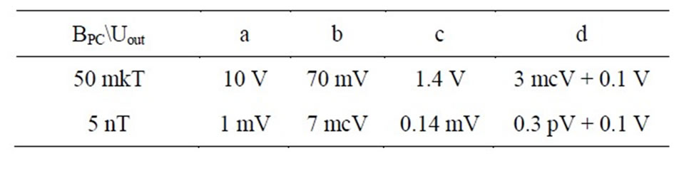
Table 1.The dependence of signal’s value Uout from the varying MF BPC.
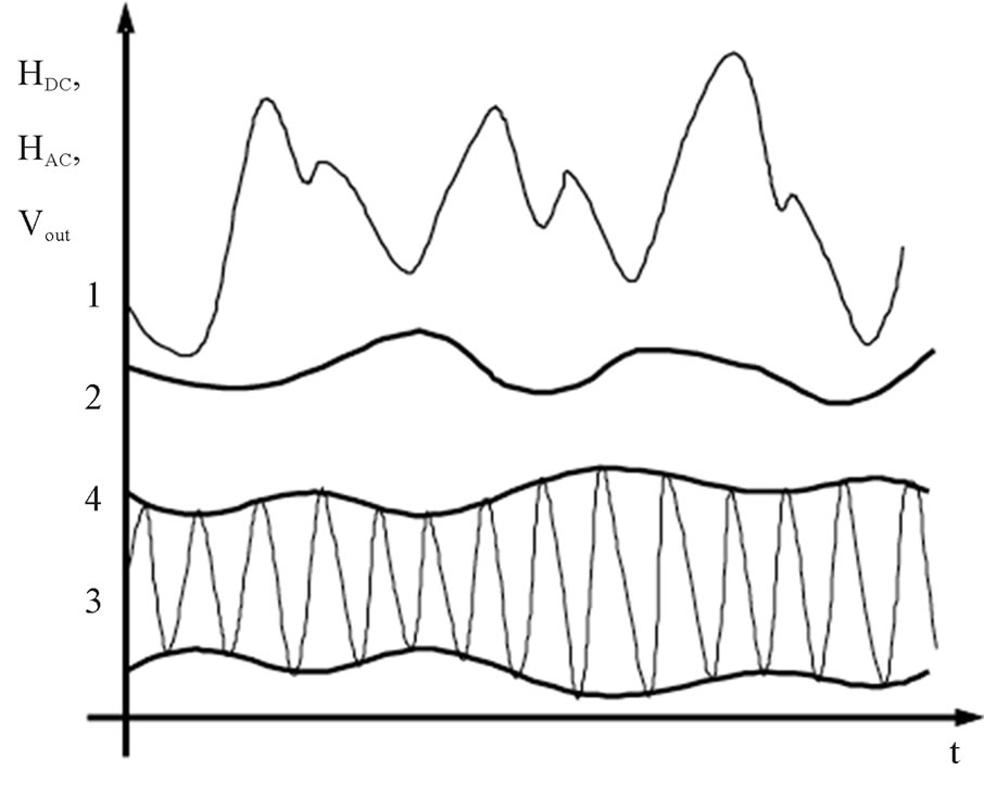
Figure 12. The variations of measured MF strength HDC, HAC: 1-oscillations of a PC modulated by variations of external natural MF; 2-an envelope of sensor’s output voltage UDC as the appropriate quasi-DC MF along the walking way; 3-changing of an AC industrial MF interference into the travel space; 4-the integral output voltage UAC which determines changing of the interference's power by a distance.
a similar manner, way an AC MF partial can be shown.
The linear travel of the robot can be derived from the known distance between any two limbs and measured during the movement gradient of MF ΔH, which is presumed constant. Otherwise, the robot can be walking in the direction of minimal or maximal MF strength H according to the said gradient (Figure 13). In both cases the precision of movement will be defined by the sensors’ sensitivity, which lies in a range of the orders from pT/√Hz to fT/√Hz.
1) Determination of the earth’s MF gradient
A portable single axis magnetic gradiometer, which is a relative instrument because it measures the spatial
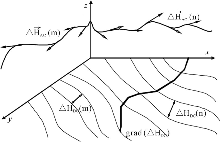
Figure 13. 3D Orientation of the walking robot in an environmental MF: a) distribution of the detected gradients of DC natural MF over the x-y plane; b) distribution of DC MF interference in the space around z axis as a difference between the limbs.
variation of the MF, has been described [24]. The finite distance d between the magnetic sensors for detecting the field difference is used to get an expression for the estimate of the exact magnetic gradient, adjusted by the function of the field distanceΔBz = Bz (z + (1/2)d) Bz(z
Bz(z (1/2)d), as follows:
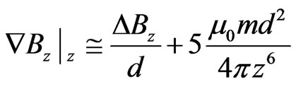 (4)
(4)
where z is the distance from the dipole to the center of the gradiometer probe and m the magnetic moment of the dipole.
In the following case, the oscillations of the limbs are taking place according to the law closer to harmonical. Then the magnitude value of magnetic induction, which produced by oscillations of PC in the ambient DC MF Bz is:
 (5)
(5)
where α is an angle between PC's direction of detection and vector of B, Δα is a range of a value of this angle variation.
Having substituted Equations. 1, 3, 5 into Equation. 4, we have the dependence between signals from PCs of any two limbs and the relevant magnetic gradient occurs:
 (6)
(6)
A first order radial gradiometer consists of two axially displaced magnetometer loops, wound in an opposing way from a common wire that is connected to IS. Two radial magnetometers with opposite polarity can be connected together to form planar gradiometers [24]. Such devices detect the tangential gradient of the radial field, and two gradiometers are usually used at each site to detect two orthogonal planar gradients. The planar gradiometer behaviour is qualitatively different from that of the radial gradiometer.
2) Measuring of the MF signal in a triaxial arrangement
A flux transformer detects more environmental noise if its baseline is long (or if it is a magnetometer). Thus long baseline gradiometers detect not only stronger signals from deep sources, but also larger environmental noise. The noise parameters for different baselines were measured and are shown graphically [25]. Gradiometers can also be configured to detect the radial gradient of the tangential MF. Two orthogonal ‘tangential radial gradiometers’ and one ‘radial gradiometer’ can be combined to form a first-order gradiometer equivalent of the vector magnetometer. The vector of the industrial or household man-made AC MF (noise) ω can be measured during the complete pass of the robot’s walking. Placing of the PC’s triplets (the three orthogonal components at each location) on the respective limbs give the necessary data for the triaxial MF determination according to the geometrical summation. In such a case, the frequency of the limb’s oscillations is much lower than ambient MF noise. That is why, they do not influence the measured components and, moreover, these oscillations can be additionally suppressed by a passive LF filter [26]. The value of MF induction along a single component will be calculated similarly to Equation. 1 and Equation. 2 by the formula:
 (7)
(7)
The dependence of volumetric error on the baseline for environmental noise is shown [25].
3.3. Experimental Validation of the Method
In the Figure 6 are shown the oscillations of an electromotive force 2-3 of the described PC with respect to the basic voltage 1, which are conform to MF B0 with an onward movement speed of IS 1 m/s. The signal-wave envelope 4 is a result of the informational-measuring process and confirming about the space distribution of the MF variations, which are bases for the advanced perception-guide abilities. The levels of the IS’s output signals and boundaries of their changes in reality for all the described devices’ variants are shown in Figure 14.
In order to improve reliability of the method and increase the working frequency intensity signal filtration outside, a working frequency is introduced. Interference suppression is achieved by introducing n-unit RC-filters into the input stages of preamplifier intensification.
The equation for LF filtration is of the sixth order relative to RC:
 (8)
(8)
where αL and ωL are the interference suppression factors.
The experimental curve, given in Figure 15 confirms the computed values of suppression a transfer function G for a two-unit RC-filter. It is also possible to apply a twin-T RC-filter, but only for the HFfH, relative to the working one fwork [22]. The response curve in the frequency range that is of importance for orientation, would be virtually flat GF, when R and C are related to each other as follows:
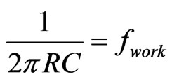 (9)
(9)
As a result, the working MF frequency will be effectively “cut-out” from the rest of oscillations, both of EM and mechanical origin [26].
3.4. MF Feeling with a Living Being-Machine
Interface
The design provides a means to update operating-, monitoring parameters, operational thresholds, and sensor and RF link specific firmware modules “over-the-air”. It is composed of two main components - a sensorwireless hardware interface and system integration framework, which facilitates the defining of interaction between sensors/actuators based on process needs. The intelligence necessary to process the sensor signals, monitor the functions against defined operational templates, and enable swapping of sensor and RF link, resides on the microcontroller of the hardware interface [27].
The basic scenario is shown in Figure 16. As a result living beings control drives by previously translated biosignals. In the other variant, biosignals from organs of the senses or brain transduce directly into intelligent or robotic systems which, in such a way, pick up environmental information.
Let us consider the connection between the input (biosignal Inerve) and output (MF B) variables of the autonomous system in the wide frequency range ωB:[28]
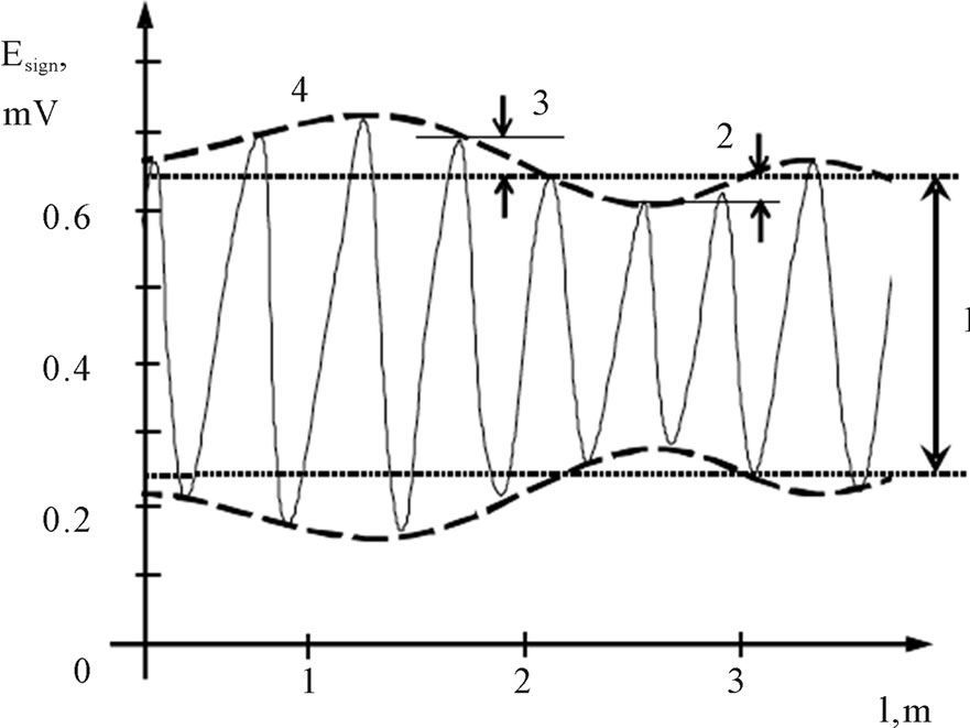
Figure 14. The magnitude changes of orientate on MF frequency during the walking path.
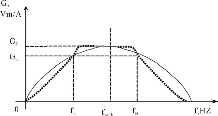
Figure 15. The simultaneous effect of both LF and HF filters on interferences in wide frequency range.

Figure 16. The living being-machine interface in the biorobotic perception system.
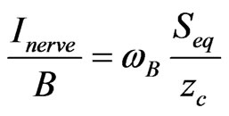 (10)
(10)
Taking into account Equation. (6) is possible to calculate the relation between sensor out-in (Inerve) and actuator in-out (Uout) respectively when robot’s limbs are oscillating with the frequency ωlimb.
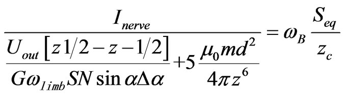 (11)
(11)
Simulated qualitative performance data of the human robot interface in the ambient MF B are shown in Figure 17.
4. Multisensor Data Fusion for the Medium and Environment
Recent developments in bioengineering, nanotechnology, and soft computing make it possible to create a new generation of intelligent sensing. There are developing opportunities for combining natural and artificial sensing abilities in the synthesized system. Backed up by the rapid strides of nanotechnology, nanosensor research is making a two-directional progress, firstly in evolving new sensors employing mesoscopic phenomena, and secondly in the performance enhancement of existing sensors. Nanosensors are nanotechnology-enabled sensors characterized by one of the following attributes: either the size of the sensor or its sensitivity is in the nanoscale, or the spatial interaction distance between the sensor and the object is in nanometers. These nanosensors have been broadly classified into physical and chemical categories, with the biosensors placed on borderlines of biological signals with the remaining classes [29].
With continued miniaturization of information sensing, computing, and processing technologies, it now seems likely that insects could be navigated as mobile information gatherers. Therefore, our specific methodology has broad implications not only for studying the isect – machine interface but also for the future use of navigated insects as environmental sentinels. When instrumented with equipment to gather information for environmental sensing, such insects potentially can assist man to monitor the ecosystems that we share with them.
Highly miniaturized CMOS electronics on micromachined probes has enabled complex BCI. Developments in microprobe technology have shifted the notion of vertebrate implantable neuromotor prosthetics from science fiction to reality. This technology provides techniques and tools to understand and generate robust electronically controlled muscle movement [30]. The adoption of the payload by the body, as the developing tissue forms around it, not only ensures a secure attachment to the insect, but also enables a highly predictable electronic interface to the insect’s sensorial, neural, or muscular systems. We call this procedure Early Metamorphosis Insertion Technology (EMIT). EMIT procedure allows for reliable IMI and hybrid bioelectronic structures where CMOS devices and MEMS structures are coupled with insects natural sensors and actuators. These systems can lead to the solution of many engineering challenges by understanding and manipulating the communication and automatic control systems of insects (Figure 18).
The implanted probes can also be used to record electrophysiological signals during natural flight to study the locomotive behavior. Further feedback studies of insect muscle can be conducted to optimize the flight control. In this study, the recording capability was used solely to assess the success of bioelectrical coupling (Figure 19).
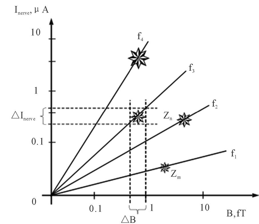
Figure 17. The sensor―actuator signals (ΔInerve―ΔB) for the different distances z under the effect of MF with some frequencies f1 … f4.
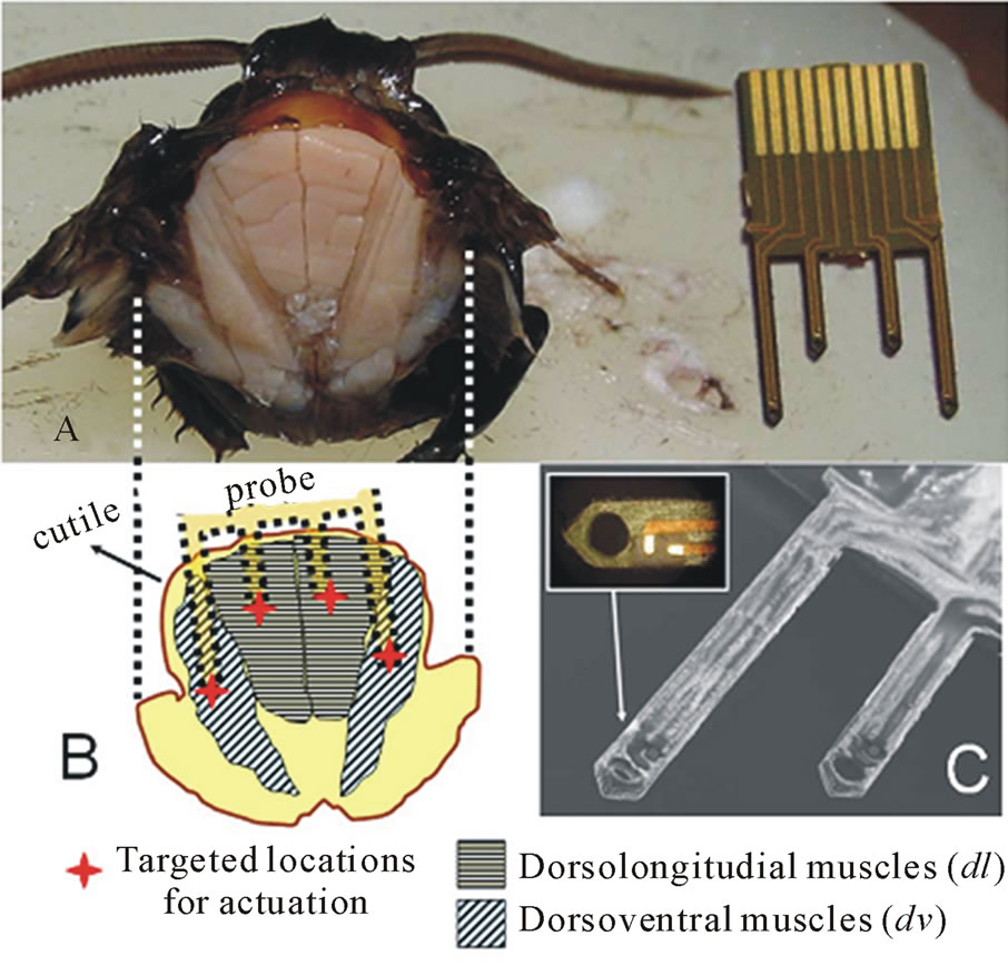
Figure 18. (A) Cross section and (B) illustrated diagram of the flight muscles powering the upand downstroke of Manduca sexta wings. The tips of the flexible probe in (A) target the flight powering muscles dl and dv (B). SEM image of the flexible-probe tip with expanded image of the ground and actuation pads can be seen in (C). The hole at the tip is opened for muscle growth. Copyright 2009 IEEE.
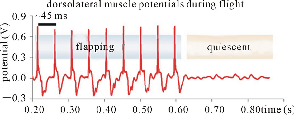
Figure 19. Actuation probes were also used to record muscle potentials as an indication of efficient tissue–probe coupling. Potentials recorded from the dorsolongitudinal muscles (multiple-cell recording with 50 – 100 times amplification) have spiking frequency similar to wing-flapping rate (~23 Hz). Observed spikes disappeared immediately when wing flapping stopped. Copyright 2009 IEEE.
Multiprocessor data fusion is in effect intrinsically performed by animals and human beings to achieve a more accurate assessment of the processing environment. The aim of signal processing by the combined artificial-living being multiprocessor system is to acquire complete information, such as a decision or the measurement of quantity, using a selected set of input data stemming to a multiprocessor systemdigital data are coming to artificial processor and the rest of information consumes by a neural system of living being. Thereby, a big amount of available information is managed using sophisticated data processing for the achievement of a high level of precision and reliability.
It is possible to substitute the microcomputer in an object-oriented problem solution scheme by the natural processing organbrain or spinal cord. As a result, the software component will be eliminated and the most general characterization of the processing problem in one-coordinate dimensional calculations could be acquired naturally, according to the feedback reaction on the input exposure for calibration, error correction, scaling up or down, range extension, sampling, resolution, etc.
Multisensor data fusion is in effect intrinsically performed by animals and human beings to achieve a more accurate assessment of the surrounding environment. The described intelligent system is introducing a new multisensor-brain interface [9].
High-channel count recording microsystems are needed to record from a growing number of sites in the central nervous system. These devices are intended to provide high investigation accuracy in neuroscience experiments, and retrieve the control signals in prosthetic applications [7]. They are mainly composed of a microelectrode array assembled and enclosed with integrated circuits (ICs), implementing the active part. Figure 20 shows the output sequence responses of the ASICs when the constructed test signals are attenuated and used as input signals to the multichip interface.
Coverage can be achieved by designing some kind of density control mechanism, that is, scheduling the sensors to work alternatively to minimize the power wastage due to the overlap of active nodes’ sensing areas [31]. The sensing area of a node is a disk of a given radius (sensing range). The sensing energy consumption is proportional to the area of sensing disks by a factor of μ1, or the power consumption per unit. Then, the sensing energy consumption per (unit) area (SECPA) is E = μ1·D, and for model we have:
 (5)
(5)
If every four equal neighboring disks in model are tangent, then there is a gap between them (see Figure 21). That uncovered space may be covered by one extra disk.
If the energy consumption of a disk of radius r is proportional to r2, n ≥ 2, then one could save energy by decreasing the radius of an extra disk. In order to decrease the radius r of an extra disk and to preserve the coverage, the neighboring disks of radius R must overlap. Though this overlapping may be small, the radius r may decrease gradually. We seek an optimal radius r for the extra disk, and this determines the extent to which the disks of radius R overlap. This case is intermediate between the previous models, and we will illustrate its advantage over them.
The tile is a square with vertices in the centers of four neighboring disks of radius R (see Figure 4, 6). Note that in that case, the diagonal disks do not intersect, but all
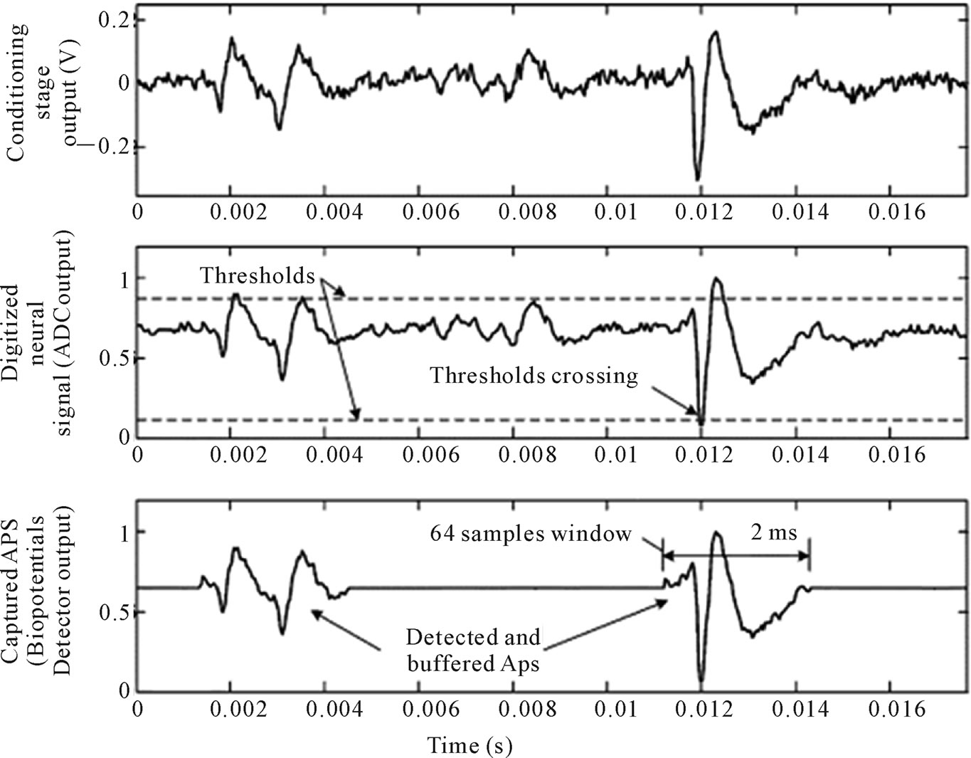
Figure 20. Measured outputs of the different stages of the multichip interface. output signal of the conditioning circuits (top), reconstructed output of the ADC (middle), and reconstructed output of the digital ASIC (bottom). only detected waveforms are captured and transmitted. Copyright 2009 IEEE.
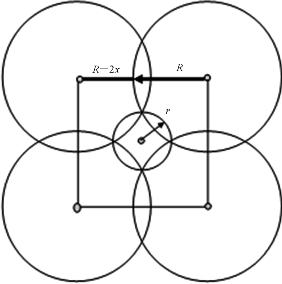
Figure 21. Optimal arrangement of sensors with two adjustable sensing ranges. Copyright 2009 MDPI Publishing.
these four disks are the neighbors of an extra disk of radius r.
As a result, we have the ratio of the total area Sf = 6πR2/5 of the parts of disks inside the tile divided by the area Sp= 16 R2/5 of the tile, and the coverage density D = 3π/8 ≈ 1788, and E ≈ 1.178 μ1.
5. Results
1) It is possible to apply a twin-T RC-filter for combating such interferences and noises, but only for the FR on the high or decreasing part of the transfer function (TF). The improvement of metrological performance data from the induction MF transducer by suppressing the considerable interferences in the low part of its frequency range where TF is rising was proposed. Suppression of such interferences is achieved by incorporating n-unit RC-filters into the input circuits of the transducer with a negative magnetic flux feedback loop;
2) A magnetometer-based motion capture system that can address several usual human movements has been presented. This approach is well suited to planar movements which are classically performed by humans. Furthermore, in an advantageous way, this angle information with an accelerometer to separate the gravitational and kinematical components in the accelerometric signal can be combined;
3) Recent developments in bioengineering, nanotechnology, and soft computing make it possible to create a new generation of BCI. There are developing opportunities for combining natural and artificial sensing abilities in the synthesized system. It is generally commented that there exists an overwhelming variety of nanosensors. Taken as a whole, nanosensors are providing comparable or superior performance to their microsensor competitors, at smaller sizes and in many cases, more economically.
The limits of advanced method are:
1) presence of the AC MFs which are considerable strong than the noise level of MF and walking vibrations;
2) the head sensor is connected rigidly to the robotic legs and movement is performed with a constant horizontal speed;
3) the power consumption of the autonomous robot is slightly increased for the sensor’s functioning maintenance. Also robot’s mass will be added in a case of application of a Dewar for superconducting sensor;
4) the differential arrangement of a sensing element allows a single-directional perception and the three-component vector sensor can be used for orientation in a space;
5) between both sensors and actuators a mutual flow of information exists by means of the explained human robot interface. It is presumed that the nervemachine interface will allow the close monitoring of flow data which are restricting to the transducing ability of a biosensor of nerve impulses and mass-dimensional parameters of IS.
6. References
[1] E. Mahmoudi, “Electronic Nose Technology and Its Applications,” Sensors & Transducers Journal, Vol. 107, iss. 8, 2009, pp. 17-25.
[2] L. Beccai, S. Roccella and L. Ascari et al., “Development and Experimental Analysis of a Soft Compliant Tactile Microsensor for Anthropomorphic Artificial Hand,” IEEEASME Transactions on Mechatronics, Vol. 13, 2008, pp. 158-168.doi:10.1109/TMECH.2008.918483
[3] A. Cerman, P. Ripka and P. Kaśpar, “Precise Magnetic Sensors and Magnetometers for Military and Space Applications,” Sensors & Transducers Magazine, Vol. 38, iss. 12, 2003, pp. 54-58.
[4] D. J. Mapps, “Remote Magnetic Sensing of People,” Sensors and Actuators A, Vol. 106, 2003,pp. 321-325,. doi:10.1016/S0924-4247(03)00193-6
[5] G. S. Patel, A. Rai and S. Prasad, “Artificially Controlling the Limb Movement of Robotic Arm Using Machine Interface with EMG Sensor,” Sensors & Transducers Journal, Vol. 89, Iss. 3, March 2008, pp. 39-51.
[6] M. Hajjhassan, V. Chodavarapu and S. Musallam, “Neuro MEMS: Neural probe microtechnologies (Review) ,”Sensors, Vol. 8, 2008, pp. 6704-6726. doi:10.3390/s8106704
[7] B. Gosselin, A. E. Ayoub, J.-F. Roy and M. Sawan, et al., “A Mixed-Signal Multichip Neural Recording Interface With Bandwidth Reduction,” IEEE Transactions on Biomedical Circuits and Systems, Vol. 3, No. 3, 2009, pp. 129-141. doi:10.1109/TBCAS.2009.2013718
[8] R. Sklyar, “CNT and Organic FETs Based Two-Way Transducing of the Neurosignals,” Proceedings Nanotechnology 2008: Life Sciences, Medicine, and Bio Materials, Nano Science & Technology Institute, Cambridge, CRC Press, Vol. II, chapt. 6: Nano Medicine & Neurology, June 2008, pp. 475-478.
[9] R. Sklyar, “Sensors with a Bioelectronic Connection,” IEEE Sensors Journal (Special Issue), Vol. 7, 2007, pp. 835-841. doi:10.1109/JSEN.2007.894903
[10] R. Sklyar,“A Complex of the Electromagnetic Biosensors with a Nanowired Pickup,” Journal of Sensors, 2009, Article ID 516850. doi:10.1155/2009/516850
[11] R. Klainer, D. Koelle and F. Ludwig et al., “Superconducting Quantum Interference Devices: State of the Art and Applications (Invited Paper) ,” Proceedings of the IEEE, Vol. 92, No. 10, 2004, pp. 1534-1548. doi:10.1109/JPROC.2004.833655
[12] R. Sklyar, “The Method of Instant Amplification of the MCG&MEG Signals,” Proceedings TechConnect World Conference and Expo 2010, Anaheim, California, June 2010, pp. 467-470.
[13] M. Hajjhassan, V. Chodavarapu and S. Musallam, “Neuro MEMS: neural Probe microtechnologies (Review) ,” Sensors, Vol. 8, 2008, pp. 6704-6726. doi:10.3390/s8106704
[14] Y. K. Song, D. A. Borton and S. Park, et al., “Active Microelectronic Neurosensor Arrays for Implantable Brain Communication Interfaces, ” IEEE Transactions on Neural Systems and Rehabilitation Engineering, Vol. 17, 2009, pp. 339-345. doi:10.1109/TNSRE.2009.2024310
[15] D. C. Ng, T. Nakagawa and T. Mizuno, et al., “Integrated In Vivo Neural Imaging and Interface CMOS Devices: Design, Packaging, and Implementation,” IEEE Sensors Journal, Vol. 8, No. 1, 2008, pp. 121-130. doi:10.1109/JSEN.2007.912921
[16] R. Gupta and J. Ashe, “Offline Decoding of End-Point Forces Using Neural Ensembles: Application to a Brain–Machine Interface,” IEEE Transactions on Neural Systems and Rehabilitation Engineering, Vol. 17, No. 3, 2009, pp. 254-262. doi:10.1109/TNSRE.2009.2023290
[17] M. Khan, A. K. Salhan and D. Bansal, “A Real Time Embedded Set Up Based on Digital Signal Controller for Detection of Bio-Signals Using Sensors,” Sensors & Transducers Journal, Vol. 105, iss. 6, 2009, pp. 26-32.
[18] H. Ramamurthy, B. S. Prabhu and R. Gadh, et al., “Wireless Industrial Monitoring and Control Using a Smart Sensor Platform,” IEEE Sensors Journal, Vol. 7, 2007, pp. 611- 617. doi:10.1109/JSEN.2007.894135
[19] R. J. Prance, T. D. Clark, and H. Prance, “Compact Room-Temperature Induction Magnetometer with Superconducting Quantum Interference Device Level Field Sensitivity,” Review of Scientific Instruments, Vol.74, No. 8, 2003, pp. 3735-3739. doi:10.1063/1.1590745
[20] S. Bonnet, and R. Héliot, “A Magnetometer-Based Approach for Studying Human Movements,” IEEE Transactions on Biomedical Engineering, Vol. 54, 2007, pp. 1353-1355. doi:10.1109/TBME.2007.890742
[21] R. Sklyar, “Superconducting Induction Magnetometer,” IEEE Sensors Journal, Vol. 6, 2006, pp. 357- 364. doi:10.1109/JSEN.2006.870167
[22] L. F. Zambresky, T. Watanabe, “Equivalent Circuit of a Magnetic Sensor Coil and a Simple Filter for Rejection of 60 Hz Man-Made Noise,” Journal of Geomagnetism and Geoelectricity, Vol. 32, 1980, pp. 325-331.
[23] P. Ripka, “Review of Fluxgate Sensors,” Sensors and Actuators A, Vol. 33, 1992, pp. 129-141. doi:10.1016/0924-4247(92)80159-Z
[24] J. M. G. Merayo, J. R. Petersen, and O. V. Nielsen et al., “A Portable Single Axis Magnetic Gradiometer,” Sensors and Actuators A, Vol. 93, 2001, pp. 185-196. doi:10.1016/S0924-4247(01)00656-2
[25] J. Vrba, and S. E. Robinson, “SQUID Sensor Array Configurations for Magnetoencephalography Applications (Topical Review) ,” Superconducting Science and Technology, Vol. 15, 2002, pp. R51–R89. doi:10.1088/0953-2048/15/9/201
[26] R. Sklyar, “Suppression of Low-Frequency Interferences in the Induction Sensor of Magnetic Field,” Measurement, Vol. 39, 2006, pp. 634-642. doi:10.1016/j.measurement.2006.01.005
[27] H. Ramamurthy, B. S. Prabhu, R. Gadh, et al., “Wireless Industrial Monitoring and Control Using a Smart Sensor Platform,” IEEE Sensors Jounal, Vol. 7, 2007, pp. 611- 617. doi:10.1109/JSEN.2007.894135
[28] R. Sklyar, “A SuFET Based Either Implantable or Non-Invasive(Bio) Transducer of Nerve Impulses,” In: Armada, M. A., Gonzales de Santos, P., and Tachi S., Eds., Measurement and Control in Robotics, Producción Gráfica Multimedia, PGM, Madrid, Spain, 2003, pp. 121-126.
[29] V. K. Khanna, “Frontiers of Nanosensor Technology,” Sensors & Transducers Journal, Vol. 103, 2009, pp. 1-16.
[30] A. Bozkurt, R. F. Gilmour, A. Sinha, D. Stern, “Insect–Machine Interface Based Neurocybernetics,” IEEE Transactions on Biomedical Engineering, Vol. 56, 2009, pp. 1727-1733. doi:10.1109/TBME.2009.2015460
[31] V. Zalyubovskiy, A. Erzin, S. Astrakov and H. Choo, “Energy-Efficient Area Coverage by Sensors with Adjustable Ranges,” Sensors, Vol. 9, 2009, pp. 2446-2460. doi:10.3390/s90402446