Engineering
Vol.08 No.03(2016), Article ID:64489,5 pages
10.4236/eng.2016.83008
Design and Fabrication of a High Voltage Lightning Impulse Generator
Attiq Ur-Rehman*, Nasrullah Khan
Electrical Engineering Department, COMSATS Institute of Information Technology, Islamabad, Pakistan

Copyright © 2016 by authors and Scientific Research Publishing Inc.
This work is licensed under the Creative Commons Attribution International License (CC BY).
http://creativecommons.org/licenses/by/4.0/


Received 4 January 2016; accepted 11 March 2016; published 14 March 2016
ABSTRACT
This paper reports 10 kV to 100 kV high voltage impulse generator. Generation of variable outputs impulse generator can be designed by combination of flyback transformer and Marx generator which can produce different high voltages. It is a portable device for field. The experimental final results have been taken by using spark gap measurements and voltage divider technique. This high voltage lightning impulse generator produces standard T1/T2 waveshape impulses. The testing of protection devices such as SPD (surge protection device) is extremely important to find out whether these devices can operate in standard conditions or not. That’s why the high voltage lightning impulse generator is developed for such testing. Similarly, our research work consists of modeling and practical design of a 100 kV impulse generator.
Keywords:
Power Supply, Flyback Transformer, Marx Generator, HV Generator

1. Introduction
Lightning is a natural phenomenon which behaves very erratically. Natural lightning originates due to partition of electrical negative and positive charges by processes in atmospheric. When the charge gets increase in numbers, then air medium between the negative and positive areas breaks down in form of a massive spark, or a charged area breaks down to surface of ground (cloud to ground stroke) [1] .
It is commonly accepted by the engineering that lightning is one of the considerable causes of failure in electric power system. It could spoil many significant components of any power system.
There are a lot of devices available in market which is used for protection against of lightning strikes. Lightning protection appliances are buildup to switch the lightning strikes to ground so that any power system is protected from breakdown due to lightning strikes [2] . These safety appliances have to test to guarantee they perform the duty at time natural lightning. To resolve the difficulty related testing using natural lightning strikes, non-natural lightning needs to be created in testing platform and this can be attained by fabrication of high voltage lightning impulse generator.
This research work has been performed because of lightning. The components used in telecom, electric power transmission and distribution networks are designed to resist natural lightning overvoltage up to a certain stage. To test the capability of these devices in order to survive lightning strikes, they are needed to be tested during manufacturing by using a “standard lightning impulse” in Figure 1.
2. Design
To design and fabricate a high voltage lightning impulse generator many techniques and methods are used such as voltage doubler, Cockcroft Walton’s voltage multiplier and Tesla coil etc. This research work reports an experimental model of HV lightning impulse generator. It has capacitor banks and switching mechanism for storage of charge and discharge just like Marx generator and having flyback transformer [3] . It will be gives better performs and excellent result with multi types of outputs for testing of different types of power equipments.
The complete high voltage lightning impulse generator system has two portions. The first portion generates high dc voltage through a rectifier circuit using power supply and fly back convertor and then second portion is consist of the Marx circuit and using these two portions the high voltage lightning impulse voltage is achieved as an output of 100 kV from the Marx Topology.
Figure 2 shows the fundamental circuit of high voltage lightning impulse generator. Each stage of Marx generator is consists of resistors, capacitors and spark gaps, is in parallel combination during charging. When switch turn on, capacitor becomes in serial and then charged capacitor added. The theoretical output voltage is given by.
 (1)
(1)
whereas N is number of stages and  is input voltage.
The Marx generator is simply RLC circuit at discharging mode.
3. Lightning Impulse Waveform
Seen from Figure 3, the standard impulse waves are usually defined by its peak values. Impulse Voltage waveform is illustrate by rise time namely T1 the fall time namely T2. The rise time is illustrated as 1.2 µs and the fall

Figure 1. High voltage lightning impulse generator.
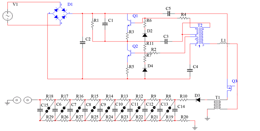
Figure 2. Circuit diagram of lightning impulse generator.

Figure 3. Standard impulse waveform [5] .
time is illustrated as 50 µs. T1 is the duration between 10% and 90% of the peak value of impulse and T2 is 50% value of the peak value of impulse. It is shown that lightning over voltage wave can be represented as double exponential waves defined by the equation [4] .
 (2)
(2)
 (3)
(3)
 (4)
(4)
4. Results and Measurements
High voltage cannot be measure directly on voltmeter that whys final results and calculation are obtained by spark gap and voltage divider techniques.
4.1. Spark Gap
A spark gap is an arrangement of two electrodes (conducting material) divided by some gap generally packed with a gas such as air, intended to allow an electric spark to pass between two conducting electrodes [6] . When the voltage variation among the electrodes goes over the breakdown voltage of the gas within the space between electrodes, a flash forms, ionizing the air and significantly dropping its resistance. Breakdown voltage  is relationship between voltage kV and gap in cm.
In this hardware air is used as medium for measuring of final spark breakdown voltage. Usually in electrical power equipments air is use as an insulating medium and standard breakdown strength for air is 30 kV/cm.
Table 1 illustrates practical observation of final spark (30 kV/cm).
The 3.4 cm spark show that the voltage is 100 kV spark is shown in Figure 4.
4.2. Voltage Dividers
On account of a capacitive divider the stray capacitances are typically unimportant, contrasted with the capacitance estimations of the divider. Typical values for a 100 kV capacitive divider are C1 = 100 pF and C2 = 100 nF. For the capacitive divider, the shunt resistor would permit the charge on capacitor C1 to leak away and series matching must be used. The resistor R is equal to Z0 and the characteristic impedance of the coaxial cable forms a divider to halve the impulse when it travels beside the line. Voltage divider equation is given as:
 (5)
(5)
By voltage divider technique the original wave form of impulse is appears at the oscilloscope [7] .
5. Conclusions
Power engineers developed numerous devices to control the induced damages due to lightning but they are still useless due to lot of reasons. One of the reasons is periodically testing of protective devices before and after installation in practical environment. As actual lightning produces high over voltage so I fabricate high voltage

Figure 4. 100 kV lightning spark.

Table 1. Breakdown (BD) voltage and spark gap distance.
lightning impulse generator. This generator generates artificial lighting up to 100 kV impulse with low current of 5 mA for testing of lightning protective devices such as SPD and lightning arresters which are used to defending our appliances by diverting high over voltage to the ground. This generator produces multi outputs for different types testing the insulation strength of cables and insures its efficiency power equipments which are used in high over voltage network.
This research paper has designed and fabricated a portable HV impulse generator’s performance which was evaluated to that of commercial impulse generators and the traditional standards for such testing instruments. The domino effects came within the ranges conventional by the international standards and this generator could thus be observed as being suitable and valid.
The generator fulfilled the major point and requirements proposed in this research work due to the low price of its accomplishment and its comfortable size for use and convey.
Cite this paper
Attiq Ur-Rehman,Nasrullah Khan, (2016) Design and Fabrication of a High Voltage Lightning Impulse Generator. Engineering,08,69-73. doi: 10.4236/eng.2016.83008
References
- 1. Khalis, M.A.Z., Nazim, M., Azizi, M.D.M. and Manan, A. (2014) From Analogue to Digital for High Voltage Impulse Generator. IEEE 5th Control and System Graduate Research Colloquium, Shah Alam, 11-12 August 2014, 181-186.
http://dx.doi.org/10.1109/icsgrc.2014.6908718 - 2. Heo, H. (2007) Compact Marx Generator for Repetitive Applications. IEEE-PPC2007, Albuquerque, 17-22 June 2007, 579.
http://dx.doi.org/10.1109/ppps.2007.4651978 - 3. Stuckenholz, C.H. and Gamlin, M. (2012) Overview of Impulse Current Test Standards and the Impact on Test Equip- ment. International Conference on Lightning Protection (ICLP), Vienna, 2-7 September 2012, 1-6.
http://dx.doi.org/10.1109/ICLP.2012.6344377 - 4. Gockenbach, E. (2012) High Voltage and High Current Test Techniques. IEEE International Conference on Condition Monitoring and Diagnosis, Bali, 23-27 September 2012, 91-94.
http://dx.doi.org/10.1109/cmd.2012.6416288 - 5. Mayes, J.R., Eubank, E., Lara, M. and Mayes, M.G. (2006) Dual Polarity MV Marx Generator System. Conference Record of the 2006 Twenty-Seventh International Power Modulator Symposium, Arlington, 14-18 May 2006, 544-547.
http://dx.doi.org/10.1109/modsym.2006.365307 - 6. Shindo, T. (2011) Lightning Parameters Used in the Lightning Protection Guides for Power Systems in Japan. Presented to 6th Meeting of CIGRE Work Group WG C4.407, Sapporo, June 2011.
- 7. Yang, S.J., Chen, S.D., Zhang, Y.J., Dong, W.S., Wang, J.G., Zhou, M., Zheng, D. and Yu, H. (2011) Over-Current Effects on Surge Protective Devices. To Be Published at XIV International Conference on Atmospheric Electricity, Rio de Janeiro.
NOTES

*Corresponding author.