Engineering
Vol. 5 No. 9 (2013) , Article ID: 36176 , 7 pages DOI:10.4236/eng.2013.59082
Development of an Efficient Tapered Slip-Form System Applying BIM Technology
1Structural Engineering Research Division, Korea Institute of Construction Technology, Goyang, South Korea
2Global Technology Cooperation Center, Korea Institute of Construction Technology, Goyang, South Korea
Email: hiyoon@kict.re.kr
Copyright © 2013 Hyejin Yoon et al. This is an open access article distributed under the Creative Commons Attribution License, which permits unrestricted use, distribution, and reproduction in any medium, provided the original work is properly cited.
Received July 13, 2013; revised August 13, 2013; accepted August 20, 2013
Keywords: Slip Form System; Construction of Concrete Pylons; BIM
ABSTRACT
Slip-form system constitutes the latest technology for the erection of elevated concrete pylons. This paper investigates the design of slip-form system applying BIM technology for the efficient development of the slip-form system. The considered pylon has a height of 10 m and presents the rectangular hollow section generally adopted in cable-supported bridges. The slip-form was thus designed to accommodate the tapered cross-section and changing thickness considering the continuous placing of concrete. In addition, the safety of the system was examined with regard to the various loads applied on the slip form along the construction. The design results could be verified visually through BIM and the applicability of the designed slip-form was validated in advance through virtual assembly and construction.
1. Introduction
The recent increase in the span length of cable-supported bridge has resulted in record-breaking heights of the pylons. The height of the concrete pylons of Russky Bridge in Russia, the longest cable-stayed bridge in the world, has reached 320.9 m allowing us to forecast that concrete pylons higher than 400 m will be erected in a near future. Even if the forms for the erection of concrete pylons are very diversified according to their purposes, shapes and operational methods, these forms can be subdivided into ordinary forms and system forms. The system form combines monolithically the form and the supporting structure strengthening the form. This system form is particularly adapted for securing the workability and safety during the erection of elevated structures like elevated pylons by modularization and enlargement of the system. The system forms applied for the construction of elevated concrete pylons are the Auto Climbing Form System (ACS) and the slip-form system. Here, slip-forming can be considered as the latest method enabling to shorten effectively the construction period owing to the automated lifting of the form and continuous 24-hour placing.
Because the slip-form system was recognized as a temporary facility, systematic research on this topic has not been conducted to date and the system remains still designed upon two-dimensional drawings. However, the lack of precision of the numerical indications in the 2D drawings often result in repetitive redesigns due to the numerous design errors occurring in the fabrication and erection stages leading to additional costs, time delay and loss of data. Moreover, the 2-dimensional representation of a 3-dimensional structure is usually degrading the understanding and sharing of the data related to the shape.
This paper presents the study carried out to achieve efficient design of the tapered slip-form system by adopting BIM (Building Information Modeling) technology. To that goal, the elements composing the slip-form are examined, and the technologies accommodating the tapered section of the members to be constructed are derived. Based on the developed element technologies, a slip-form system for the erection of a 10 m-high concrete tapered pylon is designed. The structural safety of the slip-form is verified considering the various loads acting on the slip-form during the erection of the concrete pylon. In addition, 4D virtual construction is conducted based on the 3D models of the components combined with time data so as to predict the erection process and identify eventual interference between the members during the construction.
2. Tapered Slip-Forming
Slip-forming is a method erecting the pylon by sliding up the whole form using an automated jacking device embedded in concrete and pouring continuously concrete once concrete has developed early strength enabling it to stand by itself after placing.
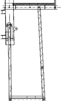
The slip-form system is composed of forms, yokes, automated jacking devices and a working platform. The forms are members used to shape poured concrete and constituted by a number of panels linked to have a shape identical to the structure to be constructed. The yokes are members framing the slip-form and support the whole system including the forms and working platform. The automated jacking devices are composed of hydraulic jacks and rods and fulfill the vertical slip-up of the yokes and the form system suspended to the yokes. Following, the hydraulic jacks shall have sufficient capacity to lift the weight of the whole system and sustain the working loads. The hydraulic jacks are installed at the centers of the yokes and the rods pass through the jacks and are embedded in concrete. The platform has 3 levels composed respectively by a top deck, working deck and hanging deck.
3. Design of Slip-Form Accommodating Tapered Section
3.1. Composition of the System
The slip-form system is composed of the forms shaping concrete, the hydraulic jacks providing the lifting force necessary for the slip-up and the yokes sustaining the whole system. The yokes sustain the whole system including the forms and working platform and lift up the whole system by means of the lifting force transmitted from the hydraulic jacks. Accordingly, the design of the slip-form shall start by arranging the yokes and determining the capacity and number of jacks considering the scale and shape of the pylon. For the design, it is assumed that a 10 m-high pylon will be erected. The pylon is tapered vertically with a rectangular hollow cross section as generally adopted in cable-supported bridges. Moreover, one side of the pylon is planned to have a thickness varying with the height. Figure 1 describes the details of the pylon.
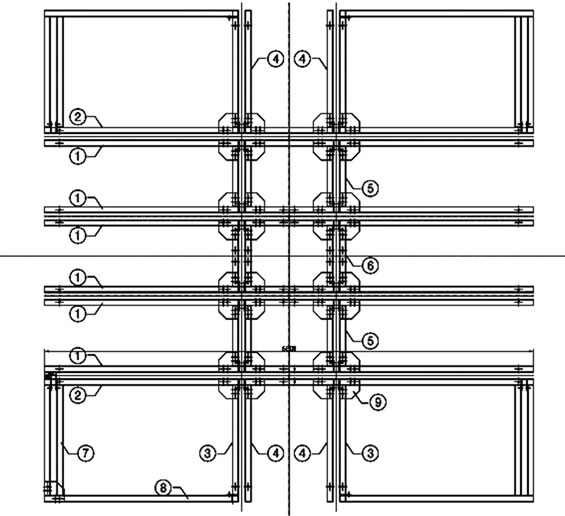
A total of 10 yokes are arranged considering the size of the pylon’s section. Twelve hydraulic jacks with capacity of 60 kN are used (Figure 2). The forms have a
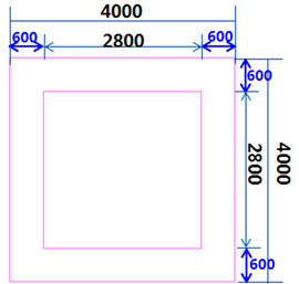
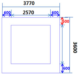
Figure 1. Cross sectional shape of the pylon.
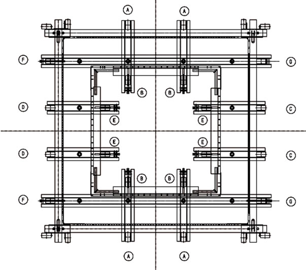
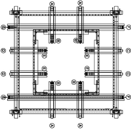
Figure 2. Arrangement of yoke channels and hydraulic jacks.
height of 1.25 m based on previous erection examples and to ease the assemblage of the rebars. Traditional steel panels and lightweight GFRP panels are applied for the forms [1]. The walers playing the role of stiffener of the forms are disposed in two rows in each side. The platform has 3 levels composed respectively by a top deck, working deck and hanging deck (Figure 3).
3.2. Design of Members Adaptable to Tapered Sections
The conventional erection of concrete pylons proceeds successively by placing the concrete batch up to the height of the forms, removing the forms after completion of curing and lifting of the forms. In slip-forming, placing of concrete and lifting of the forms are conducted continuously. For the construction of a tapered section, this implies that the members should be designed so as to enable continuous modification of the forms. Accordingly, this study investigates the design of the slip-form members accommodating continuously the sectional dimensions and thickness varying with the height of the pylon.
First, spindles are installed in the walers to accommodate the varying dimensions of the section. The size of the forms is adjusted by controlling the length of the spindles, which makes the panels of the forms overlap. In case of large dimensional change resulting in complete overlapping of the panels, the size of the forms can also be adjusted by removing these panels. The spindles should thus be disposed where the dimensions are varying. The sectional change is planned to occur at the corners. Therefore, a total of 32 spindles are installed and disposed in two rows in each corner of the external and internal form walers (Figure 4).
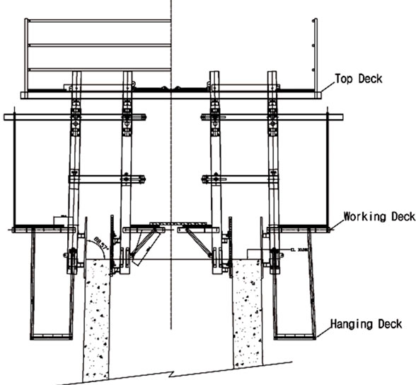
Figure 3. Three-level working platform.
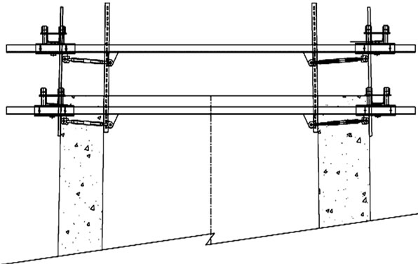
Figure 4. Arrangement of spindles.
The forms are composed of panels in modularized structure to ease their accommodation to the sectional change. Steel panels are used for the internal form and lightweight GFRP panels are used for the external form. In this study, since the dimensional changes are planned to occur at the corners, the corner panels and ordinary panels overlap when the spindles are adjusted. When the panels overlap completely, the corresponding panels are removed to control the size of the forms.
One side among the 4 sides of the pylon is planned to have a thickness varying with the height. In order to change the thickness of the pylon, the yoke should have a structure enabling to adjust freely their spacing. Therefore, bolts are inserted in the yoke channels so as to regulate the spacing between the yoke legs by adjusting the length of the bolts. Moreover, additional spindles are installed in the top deck to supplement these bolts (Figure 5).
3.3. Design Verification
The slip-form shall be design to resist all the loads and
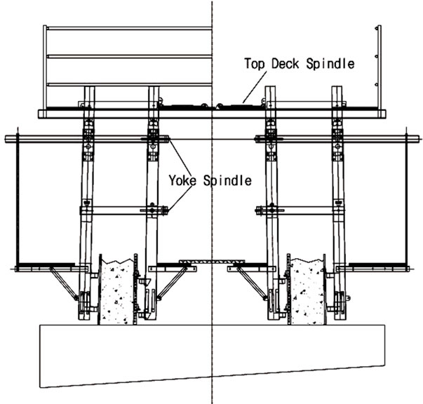
Figure 5. Yoke spindles.
environments that may occur during the erection of the pylon. In this study, the yoke constituting the frame structure of the slip-form is analyzed. The stress of the yoke and capacity of the hydraulic jacks are verified for the loads under normal operational condition and suspended operational condition of the slip-form due to ultimate wind loads.
The modeling of the yoke adopts beam elements (Figure 6). Its material is SS400 steel in accordance with KS D 3503 [2] with an elastic modulus of 210,000 MPa. For the accuracy of the analysis, the characteristics of the members linked to the yoke are reflected in the model. The hydraulic jacks installed at the center of the yoke channels are connected to the rods embedded in concrete and sustain all the vertical loads acting on the slip-form. Therefore, springs with large stiffness (2000 kN/m) are disposed at the nodes located at the emplacement of the jacks. Moreover, the nodes at the emplacement of the walers have their horizontal displacement restrained to consider the walers sustaining the lateral pressure of concrete.
During the structural stability check, the vertical loads due to the members located at the top of the yokes including the weight, the live loads applied on the working platform, the lateral pressure of concrete and the wind loads, and the frictional loads provoked by slip-up are considered. The verification is conducted through the allowable stress method in accordance with Standard specification for temporary works [3]. The structural verification is performed using the commercial software MIDAS CIVIL 2012. Figure 7 shows the moment diagram of the yoke subjected to the permanent loads.
Table 1 arranges the reactions of the hydraulic jacks and stresses of the yoke subjected to various load com-
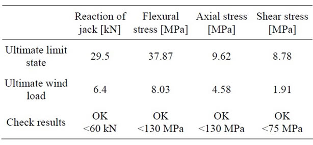
Table 1. Results of yoke design check.
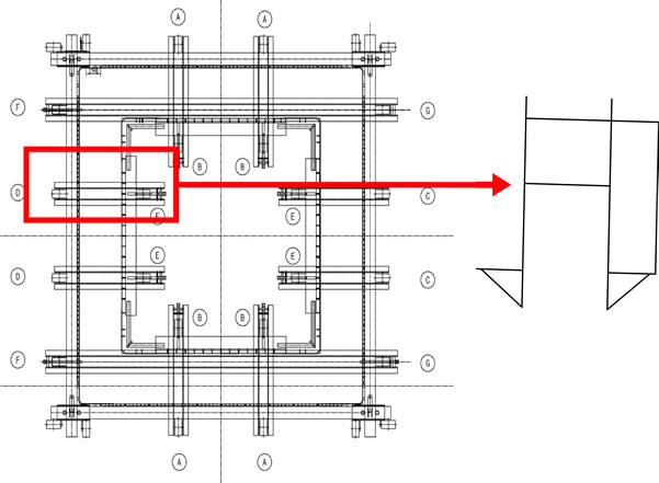
Figure 6. Analysis model.
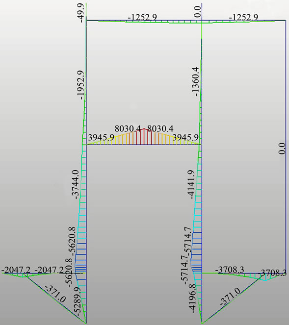
Figure 7. Moment diagram under permanent loads (unit: kN/m2).
binations. Note that the hydraulic jacks in the slip-form system sustain all the loads acting in the vertical direction. Considering that the reaction of the jacks at the ultimate limit state reaches 29.5 kN and that the capacity of each jack is 60 kN, it appears that the capacity of the jacks assumed in the design is sufficient. In addition, the maximum stress developed in the yoke is also compared to the allowable stress of SS400 steel specified in the Korea Highway Bridge Design Code [4]. From the results of Table 1, the slip-form designed in this study is verified to satisfy the structural stability.
4. BIM-based 3D Modeling Design
4.1. BIM
BIM is applied in diverse domains as a process embracing the management and generation of all data involved during the lifecycle of a facility from the preliminary conceptual design to the maintenance. The most attractive advantage of BIM is undoubtedly the visualization since BIM gathers the 3D-based shape and data of the structure. Moreover, BIM enables to visualize data by simulating the construction and operation processes in 4D, 5D, n-dimension by combining features like time and cost to the 3D model. Table 2 lists the exploitation of 3D-4D-BIM. At the international level, public authorities are pouring efforts to establish dedicated guidelines for the exploitation of BIM. In USA, the GSA (General Service Administration) is operating a national 3D-4DBIM program established by the OCA (Office of Chief Architecture) of the PBS (Public Building Service) in 2003. Efforts are made worldwide in many countries for the application and exploitation of BIM technology [5]. In Korea, the Public Procurement Service has enacted compulsory BIM design for the turnkey and design tendering of public buildings of more than 50 billion KRW since 2012 and plans to introduce BIM design in every public design tendering by 2016.
4.2. BIM-Based Slip-Form Design
This study conducts BIM-based design of the slip-form system. Design check and construction check were carried out based on the visualized results. First, the composition of the slip-from was analyzed to determine the LOD (Level of Detail). The members composing the slip-from are subdivided into yoke, form, automated jacking device, working platform, spindle, etc. Since the assembly method or number of the members can vary according to the height, the LOD was decided so as to enable the evaluation of the state of the system with respect to the height. The whole system at a definite height is defined as Level 1 and definition is done up to the component unit as Level 4. The errors in the existing drawings were checked by three-dimensional shape modeling of the 2D design drawings to undertake modification and supplementation. Table 3 lists representative modifications and supplementations of the 2D design.
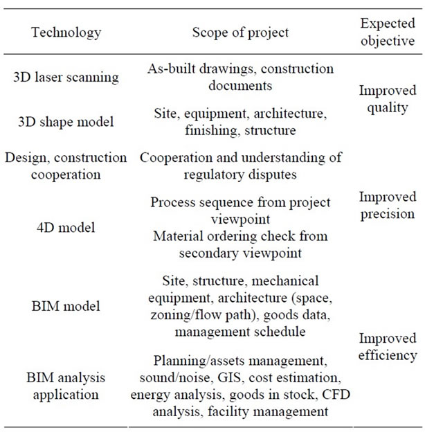
Table 2. Exploitation of 3D-4D-BIM.
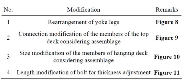
Table 3. Modifications of the 2D drawings through BIM 3D modeling.
The pylon to be erected is planned to one of its 4 sides to have a thickness varying with the height. In order to realize such construction, the arrangement of the yoke legs is modified as shown in Figure 8. In addition, the errors that may occur during the assembling of the members were checked through virtual assembling using 3D modeling and resulted in the modifications described in Figure 9 and Figure 10. Figure 11 illustrates the modification of the bolt length for the adjustment of the sectional thickness based on the BIM check. No problem was detected for the original bolt length during the virtual assembling but this length appeared to be too short when considering the height of 10 m to be erected. Moreover, the virtual assembling process made it possible to verify the interference between the members (Figure 12) and verify the position of the spindles (Figure 13).
Virtual assembling was also conducted by reflecting the site conditions with the designed members(Figure 14). This enabled to verify the position of each member as well as eventual interference between the members during the assembling or installation. Figure 15 shows
 (a)
(a)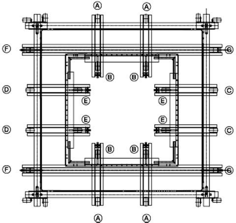 (b)
(b)
Figure 8. Modification of the arrangement of the yoke legs. (a) Drawing before BIM check; (b) Modified drawing after BIM check.
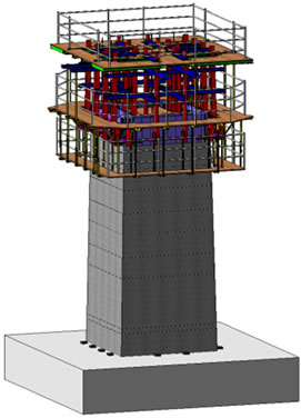
the fully assembled slip-form. Moreover, 4D simulation was conducted by adding the time data to evaluate the state of the slip-form system according to the construction stages of the pylon. To that goal, virtual construction of the pylon was implemented from the ground up to the final height of 10 m by steps of 2 m (Figure 16).
5. Conclusion
This paper presented the design of the slip-form system known to be the latest erection method for the pylons of super long-span bridges. The equipment and members constituting the slip-form were analyzed to derive solutions for the slip-form accommodating the erection of tapered sections. Therefore, the design of a slip-form system for the construction of a 10 m-high hollow section pylon was undertaken. The errors in the numerical indication, shape and assembling of the traditional 2D drawings were verified through BIM-based 3D design and corrected so as to minimize the problems that may occur
 (a)
(a)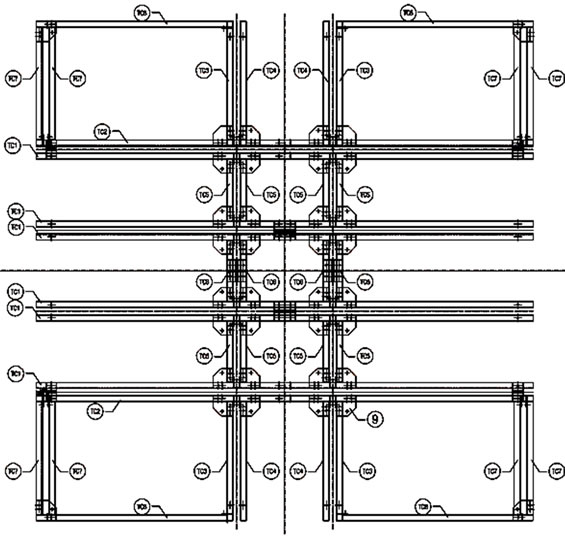 (b)
(b)
Figure 9. Modification of the members of the top deck. (a) Drawing before BIM check; (b) Modified drawing after BIM check.
 (a)
(a)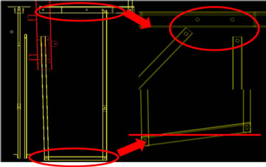 (b)
(b)
Figure 10. Error check of 2D drawing for the assembling of the hanging deck. (a) Drawing before BIM check; (b) Modified drawing after BIM check.
 (a)
(a) (b)
(b)
Figure 11. Error check of 2D drawing for the 10 m-construction. (a) Drawing before BIM check; (b) Modified drawing after BIM check.
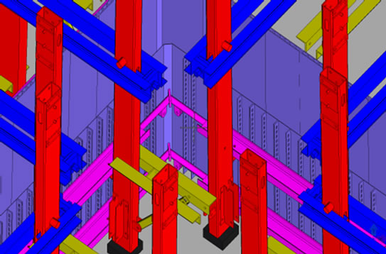
Figure 12. Check of interference between members.
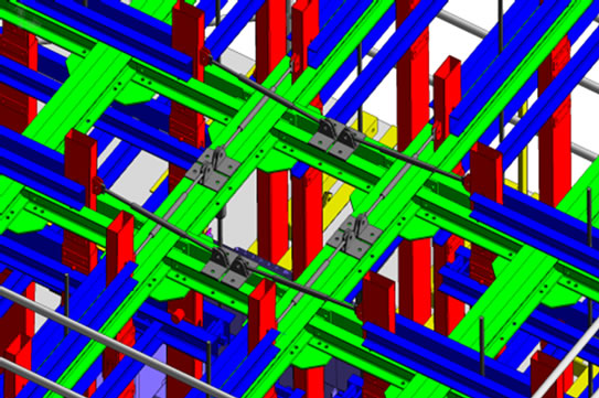
Figure 13. Check of position of spindles.
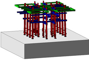
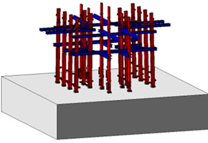
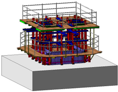
Figure 14. Visualization of assembling sequence of slip-form through BIM.
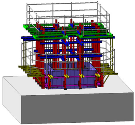
Figure 15. Fully assembled slip-form.
 (a)
(a)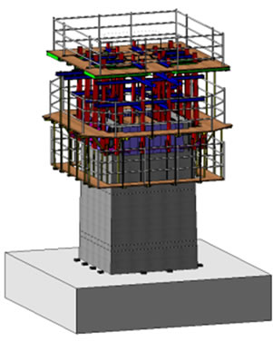 (b)
(b)
Figure 16. Digital virtual erection. (a) 6 m slip-up; (b) 10 m slip-up.
during the fabrication and assembling stages. The applicability of the slip-form system was demonstrated by means of virtual construction.
6. Acknowledgements
This paper was supported by the “Development of Accelerated Construction Technologies for High Pylons” project of the Super Long Span Bridge R&D Program. The authors express their gratitude for support.
REFERENCES
- H. Kim, “Mechanical Characteristics of GFRP Slip Form for In-Situ Application,” Ph.D. Thesis, Hanyang University, Seoul, 2012.
- Korea Standards Association, “KS D 3503Rolled Steels for General Structure,” Korea Agency for Technology and Standards, Ministry of Knowledge Economy, Gwacheon, 2008
- Ministry of Construction and Transportation, “Standard Specification for Temporary Works,” Ministry of Construction and Transportation, Seoul, 2006.
- Korea Road & Transportation Association, “Korean Highway Bridge Design Code,” Ministry of Construction Transportation, Seoul, 2005.
- C. Eastman and P. Teicholz, “BIM Handbook,” 2nd Edition, John Wiley & Sons, New York, 2011.