Engineering
Vol.5 No.10(2013), Article ID:36737,10 pages DOI:10.4236/eng.2013.510092
Proportioning of Cement-Based Grout for Sealing Fractured Rock-Use of Packing Models
1Department of Civil, Environmental and Natural Resources Engineering, Luleå University of Technology, Luleå, Sweden
2Department of Civil Engineering, University of Mosul, Mosul, Iraq
Email: Mohammed.hatem@ltu.se
Copyright © 2013 Mohammed Hatem Mohammed et al. This is an open access article distributed under the Creative Commons Attribution License, which permits unrestricted use, distribution, and reproduction in any medium, provided the original work is properly cited.
Received July 9, 2013; revised August 9, 2013; accepted August 16, 2013
Keywords: Cement; Grout; Packing models; Palygorskite; Strength; Superplasticizer; Talc; Viscosity
ABSTRACT
Fractured, very permeable rock hosting repositories for radioactive waste will require grouting. New grout types of possible use where long-term performance is needed should have a small amount of cement for minimizing the increase in porosity that will follow from the ultimate dissolution and erosion of this component. They have to be low-viscous and gain strength early after injection and packing theory can assist designers in selecting suitable proportions of various grout components. Optimum particle packing means that the porosity is at minimum and that the amount of cement paste needed to fill the voids between aggregate particles is very small. Low porosity and microstructural stability must be guaranteed for long periods of time. Organic additives for reaching high fluidity cannot be used since they can give off colloids that carry released radionuclides and talc can be an alternative superplasticizer. Low-pH cement reacts with talc to give high strength with time while Portland cement gives early but limited strengthening. The clay mineral palygorskite can be used for early gelation because of its thixotropic properties. Once forced into the rock fractures or channels in soil it stiffens and serves as a filter that prevents fine particles to migrate through it be lost. However, its hydrophilic potential is too high to give the grout a high density and high strength. According to the experiments carried out, most of the investigated grouts are injectable in fractures with apertures down to 100 μm.
1. Introduction
Sealing of rock is required for making tunnel and shaft construction possible and grouting by injecting cementbased materials for this purpose which is common in all parts of the world [1-3]. In practice, the grout does not have to be intact for more than a century but for certain cases, like repositories for hazardous waste, it must be perform for a much longer time and this requires special composition of grouts. A number of important features of cementbased grouts have been described in the literature but relatively sparse on the use of low-pH cement and almost nothing has been reported on the use of inorganic superplasticizers [4-6]. These matters are in focus in the present paper, which also describes new method for determining the viscosity of grouts and for selecting suitable aggregate/cement/water ratios by applying packing concepts [7]. It deals, in particular, with the injectability, rate of maturation, erosion resistance, and long-term chemical stability of grouts intended for sealing fracture zones that intersect rock in which highly radioactive waste (HLW) from nuclear reactors is stored. Injection is made from boreholes penetrating the zones to be sealed. Deep slim holes bored in the site selection process or larger ones which intend to place radioactive waste in them1 pass through several fracture zones that should be sealed by grouting from packed-off parts of the holes [8,9]. Clay seals are installed where the rock is tight and concrete is cast, and the holes pass through grouted fracture zones. The objective of the project described here is to indicate the availability of suitable materials for grouting relatively fine fractured rock intersected by deep boreholes, tunnels and shafts. The properties of special importance are the viscosity, mechanical strength, pH and rate of strengthening.
2. Scope
The project comprised testing of two candidate grouts for sealing and stabilization of fractured rock surrounding boreholes to be sealed with dense clay and concrete. They were composed according to modern packing theories for obtaining low porosity and minimum amount of cement paste. Talc was used as inorganic superplasticizer instead of commonly used organic additives, which can give off colloids that carry possibly released radionuclides. For one of the grout types Portland cement was used in order to get quick hardening, while the other contained low-pH cement for providing high strength with time [9]. Once injected into the fractures the granular composition gives the grouts a filtering function so that the risk of losing fines in the grouts and in contacting cast concrete is minimized in the construction period when the hydraulic gradients may still be high [10].
2.1. Basic
Cement recipes can be customized for specific tasks in the construction of an underground repository like pregrouting of fractured rock where a shaft, drift or tunnel is planned to be made, or for postgrouting of fracture zones in rock around bored holes, which is considered in the present study. The grout to be pumped into the zones must be fine-grained and have sufficient fluidity. In the first mentioned case excavation of grouted rock gives high hydraulic gradients and need for quick strengthening, while grouting of steep water-filled boreholes is made under low gradients permitting slow growth of strength. A low w/c ratio and fineness of the cement save the grout from undergoing separation of its constituents (“bleeding”) during injection. Penetration into narrow fractures is aided by a suitable fluidizer [11].
A comprehensive research program of the longevity of cement materials for grouting and serving as binder in concrete for use in underground repositories was con0 ducted by the Atomic Energy of Canada Ltd, and the US Department of Energy in the late eighties [8]. This work highlighted the possibilities and limitations of using grout based on Portland cement and showed that it will largely lose its sealing potential in 100 years. Search for long-lived grout types and techniques for effective injection into rock fractures was initiated and the presently described project shows examples of modern types developed, in particular, for being chemically compatible with clay seals in boreholes and to serve for long periods of time. The hardened grouts should be less permeable than the surrounding rock matrix and to have a granular composition that makes them erosion-resistant and serve as filters for minimizing migration and loss of fines especially where high hydraulic gradients prevail [9].
2.2. Sealing of Boreholes
2.2.1. Principles and Criteria
Figure 1 illustrates a deep hole bored in rock as part of the site investigation for location and construction of an underground repository for disposal of highly radioactive waste (HLW), It must ultimately be effectively sealed for avoiding transport of possibly released radionuclides to the biosphere [9,10,12]. This is achieved by installing dense, expandable clay seals where the rock is poor in fractures, providing axial tightness, and casting concrete where the rock is rich in fractures since clay seals placed here would be eroded and dispersed. The concrete also
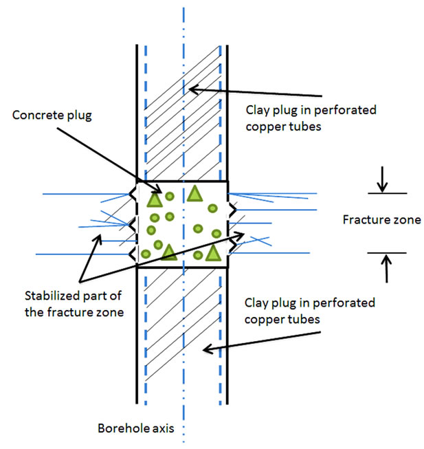
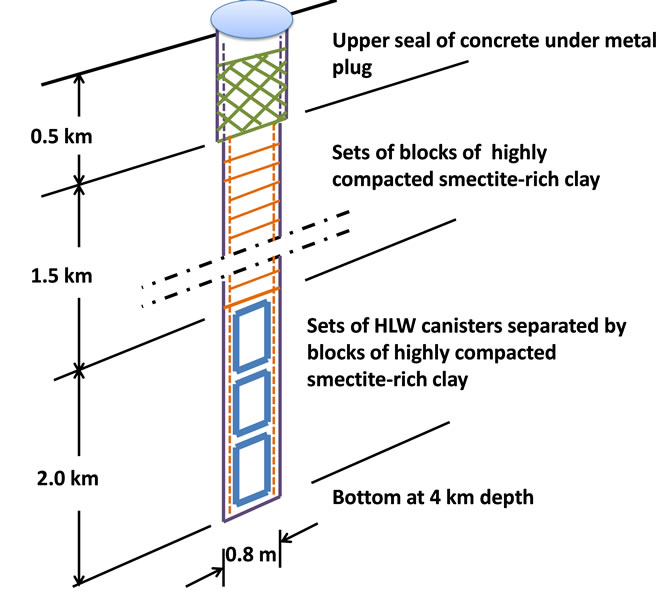
Figure 1. Borehole sealing by installing clay seals where the rock is tight and casting concrete where fracture zones are intersected. Left: Detail of concrete cast where the fracture zone has been sealed by grouting [12]. Right: VDH with clay seal from 0.5 to 2 km depth and with high-level radioactive waste canisters separated by clay from 2 to 4 km depth [9].
serves to support the clay seals. It will loose cement to the fractured rock by erosion and dissolution, which can be minimized by pregrouting the fracture zone. The possibility to find suitable grout recipes is the main objective of this document, which concerns slim holes as well as large-diameter holes for placing canisters with HLW in their deepest parts, i.e. VDH [“Medium-deep or very deep” etc.].
Planning and performance of grouting from boreholes require characterization of the rock including the following activities [13]:
● Examination for selecting parts of the boreholes that require grouting. The basis is provided by logging data of the fracture frequency and hydraulic conductivity;
● Selection of suitable grout;
● Quality assurance of materials and grouting technique;
● Planning of detailed scheme of grouting;
● Risk analysis.
2.2.2. Characterization
1) Rock Safe disposal of HLW requires that there is nearly no dissemination of possibly released radionuclides in at least 100 000 years as stipulated by a number of licensing authorities [14]. This requires that boreholes prepared in conjunction with site selection investigations or made for direct placement of canisters, must be sealed for which engineered barriers consisting of dense clay and concrete are required [15]. The problem is that groundwater percolating fracture zones that are intersected by the holes can wash out the cement content of the concrete cast there and make it enough permeable to let particles from the clay seals migrate through it and be lost in the rock. Tightening of the zones by grouting is therefore required and suitable materials for this purpose are discussed and proposed here.
2) Grout Ideally, grout should be low-viscous when injected and very stiff immediately after injection, preferably with an extra hydration potential for eliminating shrinkage. In the fully matured state, it should have substantial shear strength and be less permeable than the rock. In the present project Portland and low-pH cement were used as binders, both at low concentrations for maximizing the density and for minimizing the impact of pH on contacting clay seals. Talc was used for providing fluidity and for raising the strength by reacting with the cements. Palygorskite (attapulgite) was added for early stiffening by its thixotropic properties and for providing a filtering effect.
Focus will be here on grouting of fracture zones intersected by up to 800 mm wide VDHs, by injection of cementitious grout from packer-isolated sections of the holes but the principles are applicable also to slim boreholes of any length and orientation. The sealing role of the grout is very important and makes it one of the engineered barriers.
3. Grout Candidates
3.1. General
The principle followed was to select candidate grouts with given ratios of cement, water, and with aggregate of ground quartzite for chemical integrity. A pilot investigation, termed Series I, was followed by an extended study, Series II. The former focused on low-pH cement and the clay mineral palygorskite as additive, while the latter was conducted for comparing the impact of Portland, low-pH cement and talc on the strength, viscosity and pH.
3.2. Fluidity
Cement-based grout materials behave as Bingham or Newtonian fluids [16]. Addition of talc, which is hydrophobic, enhances Newtonian behavior while the use of palygorskite would make the grout more Bingham-like. The matter is of fundamental importance for the fluidity in the grout injection phase and determination of the viscosity was therefore of special importance in the project [17].
A further requirement for sealing fractured rock is that the grain size must be such that a significant fraction of the grout particles can enter the fractures in the rocks with a certain minimum geometric aperture, taken here as 100 micrometers. The same grout must be suitable also for sealing wider fractures [18].
3.3. Components
The bearing principle of the project was to work out a recipe for grout with low pH and high density but enough fluidity for injection into fractures. The use of finely crushed aggregate of quartzite was a prerequisite for making the grouts chemically compatible with the concrete cast in the VDH (cf. Figure 1), and for providing a large chemically active specific surface area, and also for giving the grout a high internal friction angle. The rheological properties strongly depend on the W/C ratio, and high fluidity is, in principle, not favoured by a high packing density. In practice, superplasticizers therefore have to be added for which the hydrophobic mineral talc was used [12,18]. Palygorskite was used for early strengthening of the grouts in certain tests.
3.3.1. Aggregate
The maximum grain size of the milled quartzite aggregate material was 100 µm. The grain size distribution of the aggregate is shown in Figure 2.
3.3.2. Talc
Very finely powdered mineral talc is white-coloured and has the chemical formula 3MgO∙4SiO2∙H2O. It has a very low angle of internal friction and is chemically stable in ordinary groundwater with no capacity to form gels [18]. The grain size analysis is shown in Figure 3. Manufacturer was VWR International Company, UK.
3.3.3. Cement
Two different cement brands were used: Merit 5000 lowpH cement manufactured by SSAB Merox AB, Oxelösund, and Portland cement from the Cementa AB, Heidelberg cement group, Sweden.
3.3.4. Palygorskite
Palygorskite is strongly thixotropic and commonly used in drilling muds [19]. The chemical formula is (Mg, Al) 2Si4O10(OH)4(H2O). Once forced into fractures it stiffens and has a filtering function by blocking the fractures from intrusion and migration of fine particles by the arching effect of the needle-shaped particles. The mineral particles have a length of up to 2 µm and appear as in the electron scanning micrograph in Figure 4. The material was delivered by the Greek enterprise Geohellas Co, Athens.
3.4. Microstructural Constitution
3.4.1. Conceptual
The microstructural constitution of cementitious grout is defined here by applying the criterion that the largest grains shall have an equivalent “diameter” of 100 µm and that all aggregate grains are tetrahedrons, motivated by the angular shape caused by the crushing. Calculation of their weight, being the volume multiplied by the density 2500 kg/m3, gives the number of grains belonging to the respective size fractions [18]. The size of the quadratic REV in 2D was taken here to be 2000 × 2000 µm2 and its thickness as 400 µm in order to give fair representation of all aggregate grains. The distribution of the tetrahedrons was evaluated from several randomly selected grain arrangements exemplified by Figure 5. It is schematic while the true ratios between large, mediumsized and small aggregate grains, cement, and additives were determined by using packing models.
3.4.2. Use of Packing Theories
Development of microstructural models for optimally performing grouts requires use of packing theory. The amount of binders for filling the voids in the solid mixture can thereby be minimized, which is beneficial not only from an economical viewpoint but also for reducing the loss of strength when it is ultimately dissolved [20- 22]. The degree of packing is expressed in general as the amount of solid aggregate minerals per unit volume, the mathematical expression for packing being “unity minus porosity” [23]. The granulometry and shape of the particles are factors of particular importance in determining the packing degree [22].
4. Microstructural Analysis
4.1. Microstructural Parameters
Following Pourbakhtiar [18] the microstructural modeling was based on the criterion that the largest grains have an equivalent “diameter” of 100 µm and that all aggre-
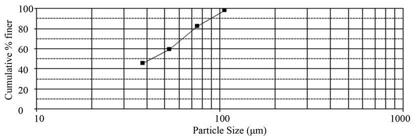
Figure 2. Grain size distribution of ground crushed and ground quartzite.
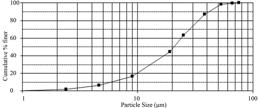
Figure 3. Grain size analysis of talc [18].
Figure 4. Palygorskite morphology. Some montmorillonite is also present [19], (Microscopy by Zander, Greifswald University).
Figure 5. Schematic view of REV of palygorskite/talc grout in 2D. It represents fine aggregate grains (blue) with cement particles (green spheres), and packets of palygorskite or talc particles appearing as thick yellow lines in the drawing. 3D equivalents were 400 μm thick.
gate grains are tetrahedrons, motivated by the angular shape caused by the crushing. Calculation of their weight, being the volume multiplied by an assumed density of 2500 kg/m3, gave the number of grains belonging to the respective size fractions. The packing degree was obtained by dividing the total solid volume by the total unit volume. All particles in the respective fraction were assumed to have the same size, and their number was calculated from the weights given by the sieve curve. The size of the quadratic REV in 2D was defined as 2000 × 2000 µm2 and its thickness as 400 µm to give fair representation of all aggregate grains of the 0 - 100 µm fraction. The distribution of tetrahedrons, representing aggregate grains of crushed quartzite, was made randomly using a number of grain arrangements exemplified by Figure 5. This picture is schematic and does not give the right ratios between large, medium-sized and small aggregate grains, nor the ratio between cement, aggregate or talc and palygorskite. They have to be determined by using packing models, of which several versions are available.
4.2. Application of Packing Theory
4.2.1. Experimental Packing Degree and “Eigen-Packing”
The packing degree was evaluated by use of a theoretical model termed 4C-Packing with commercially available software [24], and conceptual microstructural analyses described in the preceding text. A basic parameter that we will use here is the “eigen-packing”, which represents the physical state reached by pouring the aggregate mix into a container, evening out the surface and measuring the net weight of the material for determining the density [20].
4.2.2. Software
The 4C-Packing software [24] can be used for calculateing the packing degree of any combination of solid constituents like concrete and grout containing aggregate, talc, cement, etc., [25] and for designing concrete mixture. A linear packing model is the key component of the 4C-Packing software, developed on the basis of principles of packing of binary mixtures, extended to deal also with multicomponent mixtures [25,26]. It has been found to work well in predicting optimal proportions of cementitious materials [21,26] consisting of mixtures with up to six components [26]. Combination of empirical model data and this packing theory makes it possible to optimize the mixture composition. It will be used here for comparison with experimental results derived from microstructural models [27].
5. Experimental
5.1. Composition of Grouts
The grout experiments comprised two series. Series I concerned the impact of the clay mineral palygorskite on the properties of the grout with Merit 5000 cement, while Series II gave the basis for formulation of four different recipes for comparing the effect of palygorskite and talc, and for comparing the impact of Portland cement and Merit cement on the performance of the grouts.
1) Series I Three grouts termed A, B, and C were prepared with Merit 5000 low-pH cement and the compositions shown in Table 1. The content of palygorskite was varied requiring variation also of the water content in order to get the same fluidity. The densities of the grouts ranged from 1314 kg/m3 to 1394 kg/m3 (Table 1).
2) Series II Four grouts were prepared for comparing the effect of palygorskite (PA) and talc (T) on the properties of grout with Portland cement (PO) and Merit 5000 low pH cement (M), respectively. The recipes are given in Table 2. The densities of the grouts ranged from 1391 kg/m3 for the Portland/palygorskite grout to 1711 kg/m3 for the one with talc and low-pH cement. The detailed recipes are given in Table 2.
Table 1. Grout components in weight percentages of total weight and mix proportions for Series I with Merit 5000 cement (M), palygorskite (PA), quartzite aggregate (Q), and water (W).
Table 2. Grout components of investigated grouts (Series II). Merit 5000 (M) cement, Portland cement (PO), Aggregate of crushed quartzite (Q), Talc (T), Palygorskite (PA), Water (W). The components are expressed in weight percent of the total mixture weight.
5.2. Preparation of Grouts
Air-dry palygorskite and talc powders were mixed with quartzite and cement, adding water for reaching a fluid state (Figure 6). The grout samples were cast in plastic tubes and left to mature for 6, 30 and 72 hours before testing. The argument for the 6 hour time of maturation was that, in practice, stiffening must be quickly gained. The longest maturation time was decided on the practical experience that packers in grouted boreholes can seldom be left on site for more than 72 hours after injection.
5.3. Evaluation of Tests
5.3.1. Investigated Properties
The following properties were determined:
● Microstructural constitution;
● Compressive strength;
● Fluidity;
● pH.
1) Microstructure The microstructural constitution was given by the packing degree that was directly derived from the experimen tally determined density and porosity data applying the 4C program. The parameters were: the “eigenpacking”, the density and the particle size distribution of each mixture component. The packing degrees of Series I and II, are given in Tables 3 and 4.
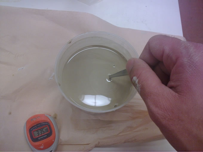
Figure 6. Preparation of grout. Notice the fluidity.
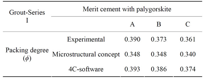
Table 3. Theoretical and experimental packing degree ϕ for series I.
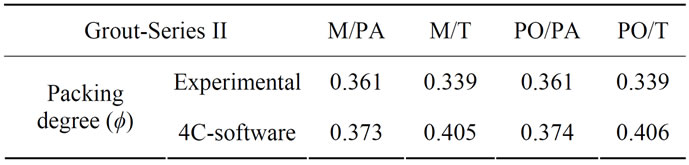
Table 4. Theoretical and experimental packing degree ϕ for series II.
The packing degree dropped slightly from a maximum value for the A-series, which comprised grouts with Merit 5000 cement and low palygorskite content (15.8%) to an intermediate value for Series B with the same cement type and 20% of palygorskite and further to a minimum value for Series C with 27.2% content of palygorkite.
One concludes that the theoretically predicted packing degrees calculated on the basis of microstructural analyses are similar to the experimental ones and to those obtained by use of the 4C software with the exception of the two Series II recipes based on talc. The packing degree, which would ideally be unity for the mixtures, is the same for the Portland and Merit grouts with similar cement contents.
2) Compressive Strength The shear resistance of grout, which is a direct function of the compressive strength, is essential in the injection phase since it determines how deeply into fractures it can reach. After maturation, the strength determines the ability of the grout to resist shear stresses and hydraulic gradients. The compressive strength of the investigated grouts, summarized in Table 5, depends on:
● Chemical reactions between the cement and the mineral constituents causing formation of cementation bonds. The reaction products are soluble while the quartz grains are stableŸ Intergranular friction after breakage of cementation bonds. It is determined by the density and hence by the packing degree.
The strength of the Merit grout samples in Series I was low and the materials exhibited ductile behavior with increasing diameter but no fracturing in the course of the compression. The strength rose from 2.5 to 6.4 kPa, and from 7.0 to 10.6 kPa, respectively, when the content of palygorskite was increased from 15.8% to 27.2% of the total solid mass, indicating that thixotropic stiffening was more important for the compressive strength than the formation of cementation bonds. The strength of the grouts prepared with Portland cement and talc in Series II was higher after 6, 30 and 72 hours (22, 184 and 307 kPa) than for any other combination of components. This grout is hence providing physical stability already in a few hours.
3) Consistency (Liquid Limit)
The results of liquid limits based on Equation (1) are collected in Table 6.
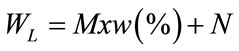 (1)
(1)
where M and N are obtained from standard tables, w is the water content, and WL is the liquid limit [18].
The data demonstrate that the grouts with palygorskite sorbed twice as much water than those with talc. Thus, for reaching the same fluidity, twice as much water has to be used in preparing grouts with palygorskite than when talc is used (cf. Tables 1 and 2).
4) Capillary Flow Test Glass tubes with inner diameters 2.3, 3.3 and 5.8 mm were filled with grout to one meter height with the valves closed (Figure 7). For the flow measurements, the valves were opened and the grout allowed to flow down by 10 cm while measuring the time. The flow rate is the cross section area of the tubes multiplied by the flow length 10 cm, divided by the flow time, which gives the viscosity by utilizing Poiseuille’s law (Equation (2)), [18]:
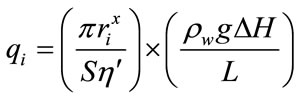 (2)
(2)
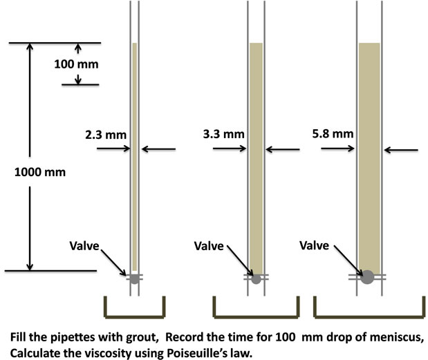
Figure 7. Principle of grout capillary test. The pipettes are filled with grout, and the time recorded for 10 cm grout flow (subsidence of meniscus).
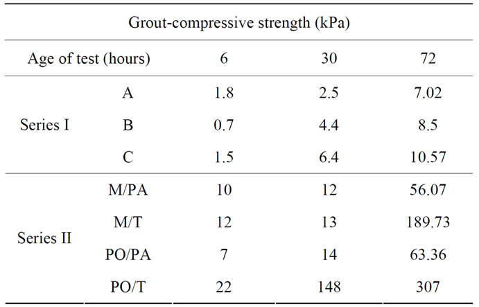
Table 5. Compressive strength of grouts in Series I and II.
where: r = mean pore radius (cm), q =flow rate, ρw = density of the grout (g/cm3), g = acceleration due to gravity (cm/s2), ΔH = pressure head difference along the flow path (cm), S = shape factor,  = viscosity (P), L = length of flow path (cm). The shape factor S and the exponent x are dimensionless parameters. For cylindrical tubes of constant diameter as in the tests, S = 8 and x = 4.
The viscosities evaluated according to this law are listed in Table 7, from which one finds that the diameter of the flow tubes was not of major importance except for the “C-grout” in Series I and the grout with Portland cement and talc. The overall conclusion, based on experience, is that the viscosity of the investigated grouts makes all of them injectable in fractures with hydraulic apertures of 100 μm and more. The fluidity was found to be particularly high for the grouts with Portland cement and palygorskite, which, in combination with the strengthening and filtering role of this clay mineral makes it a particularly interesting candidate. This is in principal agreement with the liquid limit data in Table 6.
6. Discussion
Table 8 summarizes the results obtained. The most important properties of practically useful grouts are the fluidity at injection, and the strength and rate of strengthening thereafter. As concerns fluidity the following is claimed:
● Grouts with Portland cement and palygorskite have superior flow properties;
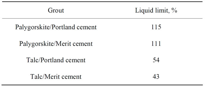
Table 6. Liquid limit of Series II grouts.
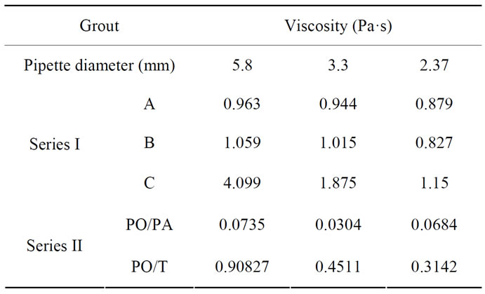
Table 7. Viscosity (Pa·s) of grouts (Series I and II) obtained according to the capillary flow test (CFT).
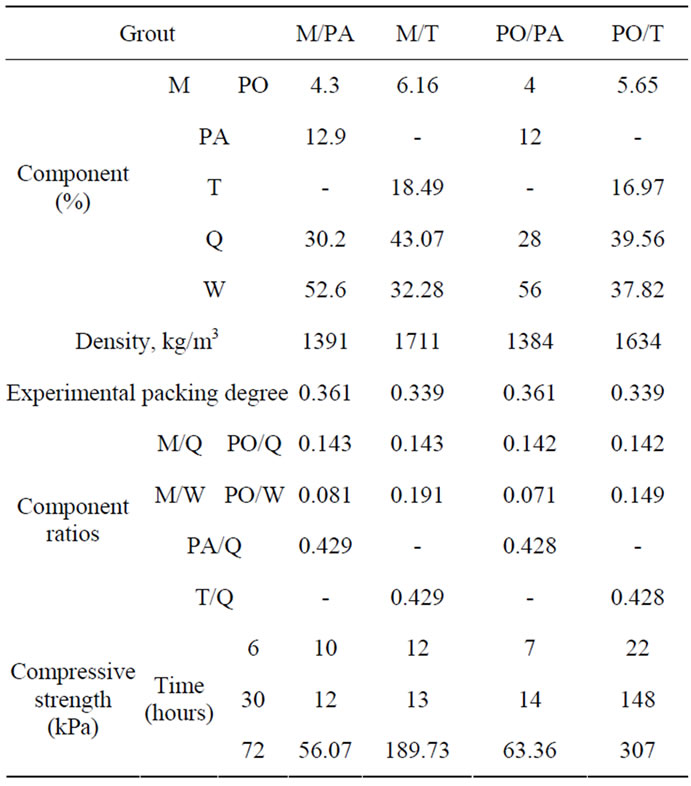
Table 8. Grout components and compressive strength of investigated grouts. Merit 5000 (M) is low-pH cement; Portland (PO); Aggregate of crushed quartzite (Q); Talc (T); Palygorskite (PA); Water (W). The components are expressed in weight percent of the total weight.
● Talc gives higher strength than palygorskite but lower fluidity. This is because the density of talc grouts is significantly higher than for palygorskite for the same fluidity;
● Grouts with Portland cement and talc gain strength quicker than the others (Series II): 22 kPa efter 6 hours, 184 kPa after 30 hours, and 307 kPa after 72 hours. Grouts with Merit 5000 low pH cement and the same fluidity stiffen slower in the first 30 hours but then behave in a similar way as the Portland cement grouts.
The different properties of the investigated grout types suggest that selection should be made with respect to the practical need. Grouts based on Portland cement and palygorskite are particularly fluid and will penetrate deeper into fractures than when talc replaces palygorskite. The firstmentioned can therefore be suitable for sealing richly fine-fractured rock where quick strengthening is not required, i.e. for grouting rock around boreholes where concrete is going to be cast. For fracture zones with fewer but wider fractures grouts with Portland cement and talc can be optimal and where long-term performance is required chemically more stable grouts based on low-pH Merit 5000 cement can be the best. By selecting palygorskite as an additive to this type of grout one would gain from the filtering function for preventing migration of cement residue and clay particles through its filtering function.
7. Conclusion
The results suggest that selection should be made with respect to the practical need. Grouts based on Portland cement and palygorskite are particularly fluid and will penetrate deeper into fractures than when talc replaces palygorskite. The first mentioned can therefore be suitable for sealing richly fine-fractured rock where quick strengthening is not required. For fracture zones with fewer but wider fractures grouts with Portland cement and talc can be optimal and where long-term performance is required chemically more stable grouts based on low-pH Merit 5000 cement can be the best.
8. Acknowledgements
The laboratory tests have been performed in cooperation with personnel from Complab at Luleå University of Technology. The authors would like to give their appreciation to them.
REFERENCES
- C. Eliasson, “Intensities as Tools in Grouting Evaluations—Using Data from the North Link and Stockholm City Line,” Master Thesis, Royal Institute of Technology, Stockholm, 2012.
- G. S. Littlejohn, “The Development of Practice in Permeation and Compensation Grouting: A Historical Review (1802-2002),” Proceedings of the 3rd International Conference on Grouting and Ground Treatment, New Orleans, 10-12 February 2003, Geotechnical Special Publication No. 120, pp. 50-100. http://dx.doi.org/10.1061/40663(2003)3
- K. Sio-Keong, “Properties of Cement Based Permeation Grout Used in Ground Engineering,” Master Thesis, National University of Singapore, Singapore, 2005.
- U. Håkansson, “Rheology of Fresh Cement-Based Grouts,” Ph.D. Thesis, Royal Institute of Technology, Stockholm, 1993.
- L. G. Schwarz, “Roles of Rheology and Chemical Filtration on Injectability of Microfine Cement Grouts,” Dissertation Thesis, North western University, Evanstone, 1997.
- M. Eriksson, “Prediction of Grout Spread and Sealing Effect, a Probabilistic Approach,” Ph.D. Thesis, Royal Institute of Technology, Stockholm, 2002.
- K. Norberg, “Packing Theory for Crushed Aggregates in Concrete,” Master Thesis, Luleå University of Technology, ETSEIB, Betongindustri AB, 2005.
- R. Pusch, G. Ramqvist, N. Bockgård and L. Ekman, “Sealing of Investigation Boreholes Phase 4,” Final Report, SKB, Stockholm, 2011.
- R. Pusch, M. H. Mohammed, J. Kasbohm and S. Knutsson, “Roles of Clay and Concrete in Isolating High-Level Radioactive Waste in Very Long Holes,” International Journal of Research Reviews in Applied Sciences, Vol. 16, No. 2, 2013, in press.
- R. Pusch, “Waste Disposal in Rock,” Elsevier, Amsterdam, 1994.
- M. Gascoyne, “Influence of Grout and Cement on Groundwater Composition,” Possiva, Working Report 07, Helsinki, 2002.
- R. Pusch, L. Warr, G. Grathoff, A. Purbakhtiar, S. Knutsson and M. H. Mohammed, “A Talc-Based Cement-Poor Concrete for Sealing Boreholes in Rock,” Engineering, Vol. 5, No. 3, 2013, pp. 251-267. http://dx.doi.org/10.4236/eng.2013.53036
- P. Bangoyina, “Ageing and Large-Consolidation of Cement-Based Grouts,” Master Thesis, University of Twente, The Netherlands, 2008.
- R. Pusch, G. Ramqvist, S. Knutsson and M. H. Mohammed, “Medium-Deep or Very Deep Disposal of Highly Radioactive Waste?” Journal of Civil Engineering and Architecture, 2013, accepted for publication.
- R. Pusch, G. Ramqvist, S. Knutsson and M. H. Mohammed, “The Concept of Highly Radioactive Waste (HLW) Disposal in Very Deep Boreholes in a New Perspective,” Journal of Earth Sciences and Geotechnical Engineering, Vol. 2, No. 3, 2012, pp. 1-24.
- Å. Fransson, “Grouting Design Based on Characterization of the Fractured Rock Presentation and Demonstration of a Methodology,” SKB Report, Sweco Environment and Chalmers University of Technology, Sweden, 2008.
- M. Westerholm, “Rheology of the Mortar Phase of Concrete with Crushed Aggregate,” Licentiate Thesis, Luleå University of Technology, Luleå, 2006.
- A. Pourbakhtiar, “Pilot Study of Method for Constructing Concrete Seals and Fracture Grouts in Deep Boreholes and Cementitious Backfills in Tunnels, Drifts and Shafts in Crystalline Rock,” Master Thesis, Luleå University of Technology, Luleå, 2012.
- R. Pusch, “Geological Storage of Highly Radioactive Waste,” Springer, 2008. http://dx.doi.org/10.1007/978-3-540-77333-7
- M. H. Mohammed, R. Pusch, N. Al-Ansari, S. Knutsson, M. Emborg, M. Nilsson and A. Pourbakhtiar, “TalcBased Concrete for Sealing Borehole Optimized by using Particle Packing Theory,” Journal of Civil Engineering and Architecture, Vol. 7, No. 4, 2013, pp. 440-455.
- V. S. Kumar and M. Santhanam, “Particle Packing Theories and Their Application in Concrete Mixture Proportioning: A Review,” The Indian Concrete Journal, 2003, pp. 1324-1331.
- M. H. Mohammed, M. Emborg, R. Pusch and S. Knutsson, “Packing Theory for Natural and Crushed Aggregate to Obtain the Best Mix of Aggregate: Research and Development,” Proceedings of WASET, International Conference on Civil and Construction Engineering, Vol. 67, No. 150, pp. 819-825.
- F. De Larrard, “Concrete Mixture Proportioning, a Scientific Approach,” E & FN Spon, London, 1999.
- Teknologisk Institut, The Danish Technological Institute, 2012. http://www.danishtechnology.dk
- M. Glavind and E. J.Pedersen, “Packing Calculations Applied for Concrete Mix Design,” Proceedings Creating with Concrete, University of Dundee, 1999, pp. 1-10.
- T. Stovall, F. DeLarrard and M. Buil, “Linear Packing Density Model of Grain Mixtures,” Powder Technology, Vol. 48, No. 1, 1986, pp. 1-12. http://dx.doi.org/10.1016/0032-5910(86)80058-4
- M. H. Mohammed, R. Pusch, N. Al-Ansari and S. Knutsson, “Optimization of Concrete by Minimizing Void Volume in Aggregate Mixture System,” Journal of Advanced Science and Engineering Research, Vol. 2, No. 3, 2012, pp. 208-222.
NOTES
1The concept is termed VDH (Very Deep Boreholes).