Engineering
Vol. 2 No. 10 (2010) , Article ID: 3174 , 11 pages DOI:10.4236/eng.2010.210097
Influence of Cutting and Geometrical Parameters on the Cutting Force in Milling
1Unité de Mécanique, Modélisation et Production (U2MP), Ecole Nationale d’Ingénieurs de Sfax (E.N.I.S.), route soukra km 4 Sfax – TUNISIE, France
2Laboratoire d’Ingénierie des Structures Mécanique et de Matériaux (LISMMA), Institut Supérieur de
Mécanique de Paris (SUPMECA), 3 rue Fernand Hainaut, 93407 cedex Saint ouen, Paris – France
E-mail: yangui_hedi@yahoo.fr
Received August 5, 2010; revised August 6, 2010; accepted August 23, 2010
Keywords: Milling, Modelling, Cutting Force, Finite Element
ABSTRACT
This paper presents a numerical modelling of the dynamic behaviour of the Machine-Tool-Part system (MOP) in milling. The numerical study of such complex structure requires the use of sophisticated method like finite elements one. Simulation is employed to predict cutting forces and dynamic response of Machine-Tool-Part system (MOP) during end-milling operation. Finally, spectral analysis is presented to see the influence of feed direction in the vibration.
1. Introduction
Milling is frequently employed in manufacturing processes for producing parts with desirable dimensions and shape. However, the quality of the obtained surface is mostly influenced by two vibratory phenomena. In the first hand, the grazing provoked mainly by the mechanism of regeneration of the manufactured surfaces leads to chatter vibration. In the second hand, a forced vibration appears owing to the periodicity of the cut. Models describing cutting tool vibrations began to appear in literature about several decades ago. Tobias [1] and Tlusty [2], almost simultaneously, published papers explaining chatter as a regenerative phenomenon which is widely accepted as a cause of self-excited vibrations on machine tools. Then, large number of dynamic models of cutter and part are presented by authors. In their work Montgomery and Altintas [3,4], use a refined time domain simulation model which incorporates the combined horizontal feed and rotation of the cutter to predict cutting force.
Because, major developments have been designed for aeronautic industry where tools are mostly more flexible than part, Altintas and Budak [5] have proposed an analytic method for computing stability lobes. They analysed the geometrical nonlinearities of the milling process. After that, they proposed a solution using Fourier series development and by considering the zero order term. In 1998, they prolonged this work by taking account of the behaviour of the part. These authors worked also on the prediction of the profile defects [7,8]. In these works the study relates the thin wall milling where the defects are due to the static deflections of the tool and the piece and the vibrations are not taken in account. Recently, there have been quite a number of published articles on the bifurcation phenomena in interrupted cutting processes. Indeed, Insperger et al. [9], Corpus et al. [10], Bayly et al. [11], Davies et al. [12], Peigné et al. [13] proposed analytical way of stability loss in milling processes. All results are approved experimentally by Bayly et al. [11], Davies et al. [12], Peigné et al. [13], Mann et al. [14,15] and R.Saffar et al. [16].
In fact, the large number of machining operations and the factors that influence each operation lead difficult to develop models for predicting the cutting phenomenon. Since, the concept of the undeformed chip thickness has been used by researchers to predict the cutting forces. In reality, it is very difficult to measure the length of the shear line and to find its relation with other measurable variables such as speed or accelerations. Consequently, the most used model is linear cutting and cutting force is proportional to the undeformed chip thickness. In this work, we start by presenting most popular models. Then, comparison between three models is presented. Finally, variation of cutting forces is presented for different cutting parameters and spectral response is also simulated.
2. Dynamic Cutting Force Models
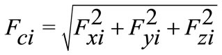
In their study M. T. Zaman et al. [17] have simulated peripheral milling to develop a three-dimensional analytical model of cutting force. So it is necessary to determine the analytical expressions for Fx, Fy and Fz which are presented in Figure 1.
Cutting force expressions (Fx and Fy) was extracted from Tlusty et al. [7] and Bao et al. [18] with little modification. In fact, they introduce in their equations horizontal component of tangential force. Thus, cutting force can be written as below:
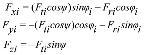 (1)
(1)
By confronting analytical and experimental study they confirm that tangential cutting force arises when cutting depth arises. Despite, this cutting force model can be used to simulate cutting force with an average of 90%.
In general, cutting force model used is the most classical. In general, cutting force depends on cutting depth. However, in dynamic milling cutting depth depends on tool and part position and the profile of machined surface (Cutting force is presented in Figure 2).
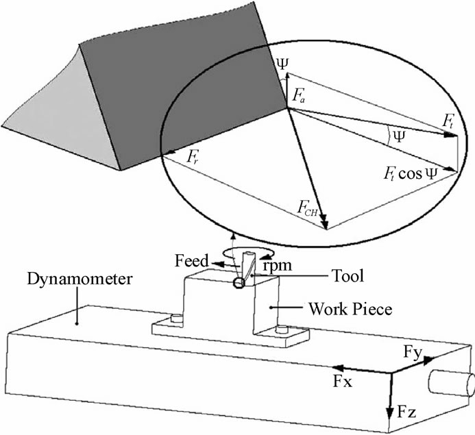
Figure 1. Cutting force component [16].
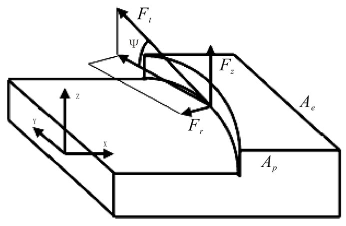
Figure 2. Cutting force model in milling.
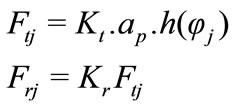 (2)
(2)
h is the instantaneous cutting thickness
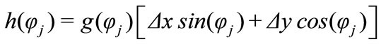 (3)
(3)
where
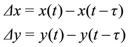
And 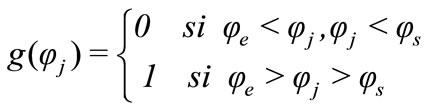
 is angle of cutter rotation of a point on the cutting edge.
Figure 3 represents tool position compared with part position, e is distance between tool and part axis,  is entry angle,
  is leaving angle.
Cutting phase is defined by angles  and
and  in the metal. These angles are calculated compared with nominal position. Thus, transitory phases of beginning and end machining are not modeled. However, if the cutting is discontinued, the tool can leave the metal.
In this case, cutting depth is null and cutting forces are also null. This non linearity permits to amplify vibration amplitude.
Angle  and
and  are defined as below:
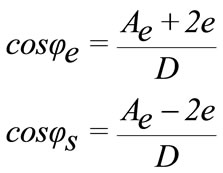 (4)
(4)
3. Dynamic Response
The first step consists to meshing the s Ma-chine-Tool -Part structure. So, voluminal elements are generated for modelling all components of milling machine,
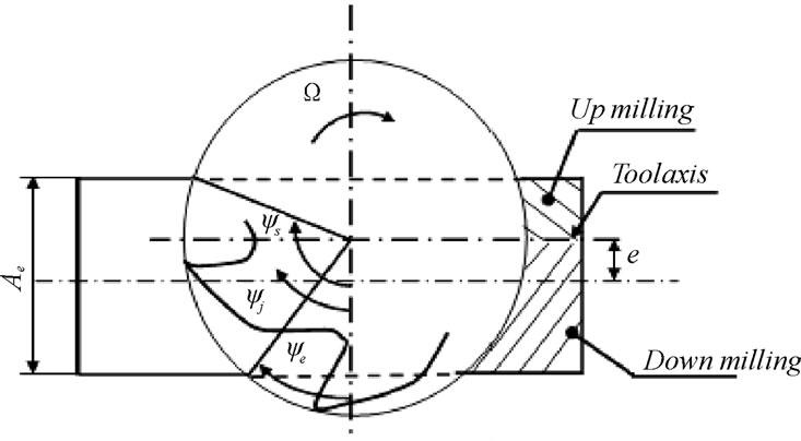
Figure 3. Tool position compared with part one.
tool and part. Figure 4 shows the photograph and the finite elements modeling of used milling machine.
Generally the dynamic analysis of the system by finite elements is reduced to the resolution of a linear system of the second order differential equations whose rigidity matrix depends on time:
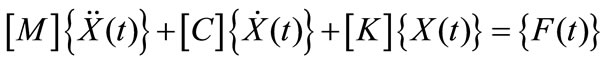 (5)
(5)
Where M, C and K are respectively mass matrix, damping matrix and stiffness matrix, X is generalized displacement vector and F(t) is cutting force vector. All coefficients of these matrixes are determined from finite element modelisation of the total system tool-machine -part.
 (6)
(6)
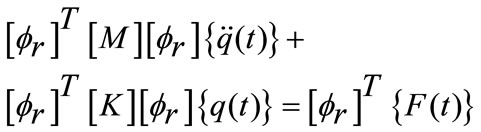
The matrix [M], [K] and [C] projected on the basis of the eigenmodes leads to matrix  by:
by:
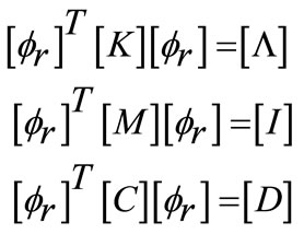 (7)
(7)
So dynamic equation projected on the basis of the eigenmodes was reduced to the system of equations in the following form:
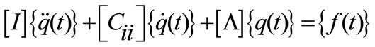 (8)
(8)
4. Numerical Results
The resolution of dynamic Equation (6) by numerical method of resolution like Newmark and Newton raphson permits the determination of the displacement of the tool in the x-y directions. Besides, cutting force variation in time can be predicted.
To validate the developed modelling of milling operation, validation test is performed. So, compa-rison with results of J. Saffar et al. [16] is presented in Figure 5.
In Figure 5 variation of cutting force according to rotation angle is presented. We remark a good agreement with J.Saffar’s results.
4.1. Comparison of Different Cutting Force Models
Table 1 presents three different model used by authors to quantify cutting force.
In Figure 6 variation cutting force is presented for three different models. We remark that for the first and third model Cutting component in y and z direction are almost equal. But, for the cutting component in x direction the difference between three models is visible.
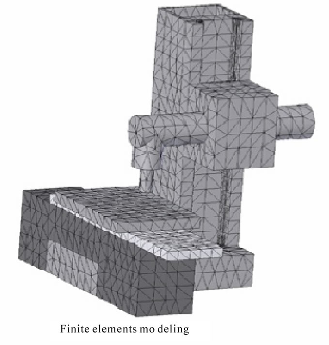
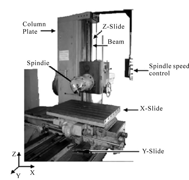
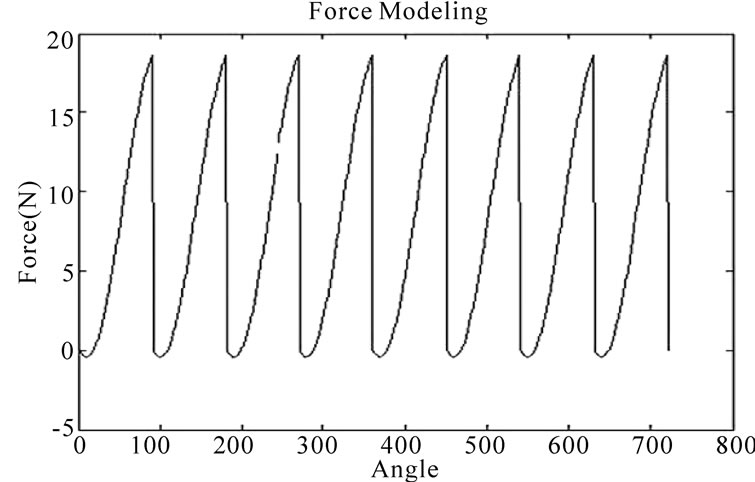
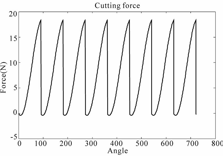
Figure 5. Comparison with saffar results.
4.2. Influence of Feed
It is clear from equation that cutting forces are proportional to feed. Figure 7 represents variation of maximal cutting force according to feed and we remark that cutting forces rise when feed rises. In addition we note that Fy component rise with an important rate. Besides, Figure 8 represents variation of instantaneous cutting force. The only difference detected is the amplitude of cutting forces.
N = 500 revs. min − 1 (Ae = 40 mm, Ap = 1 mm) for feed (f1 = 0.1 mm. rev − 1, f2 = 0.2 mm rev − 1, f3 = 0.4 mm. rev − 1, f4 = 0.8 mm. rev − 1).
4.3. Influence of Cutting Depth
Figure 9 and Figure 10 show that cutting force increase
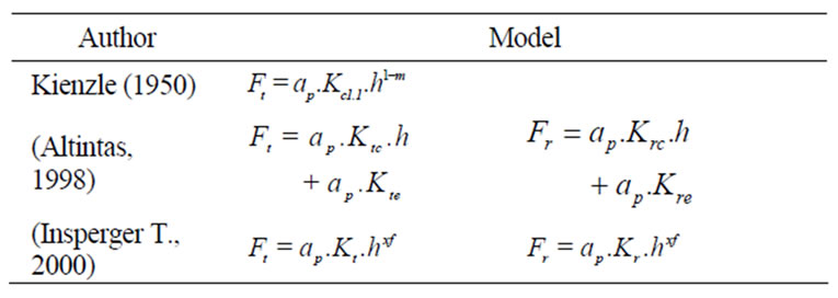
Table 1. Different model of cutting force.
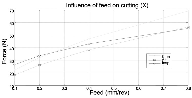
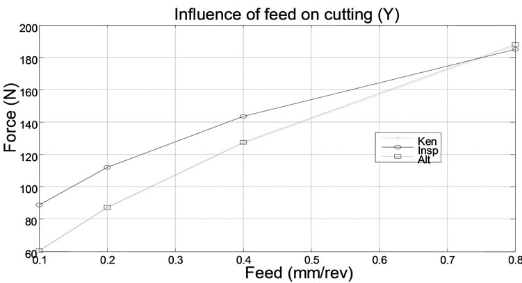
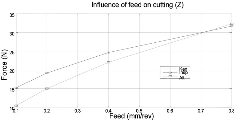
Figure 6. Comparison of different cutting force models.
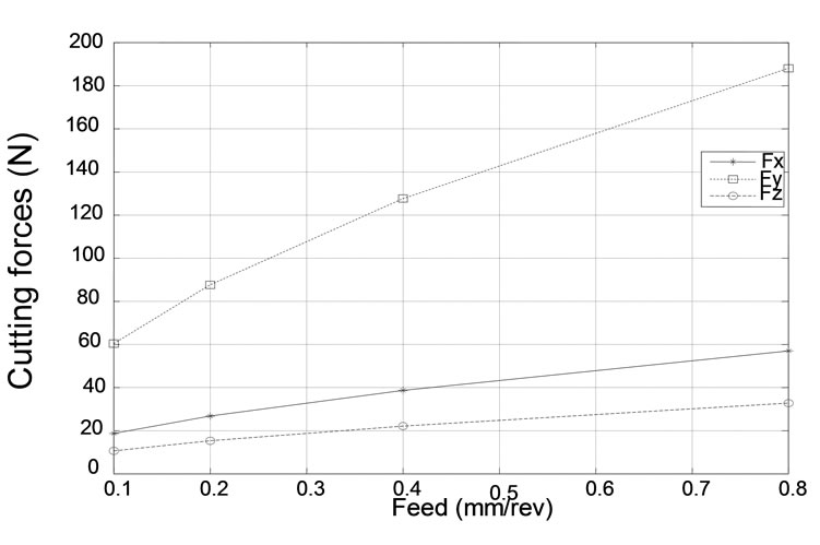
Figure 7. Influence of feed on maximal cutting forces.
when cutting depth increases. This raise is justified by the increase of the width of chip. In fact, it is the largest parameter acting on cutting forces.
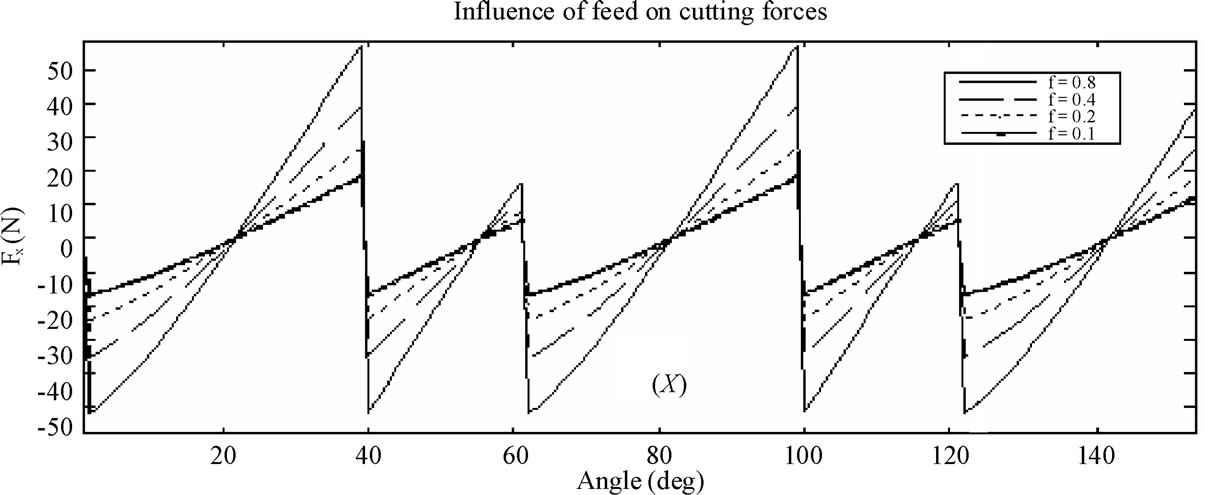
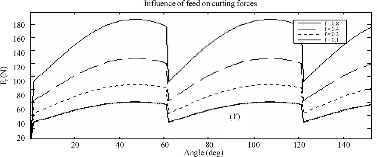

Figure 8. Influence of feed on cutting forces.
Figure 11 shows that rising cutting depth leads to rising vibration amplitude and can leads to chatter vibration. In fact, the dynamic response for Kienzel model with 5 mm cutting depth is amplified almost ten times and the response is divergent. For Atlintas model the amplitudes is less than for other model.
4.4. Influence of the Beginning Angle 
Increasing the spacing between the tool and the piece caused a slight increase in the cutting force. Figure 12 shows the influence of the angle of entry on the cutting forces because the period of machining for each tooth has increased (for e = 20 mm and e = –20 mm).
4.5. Influence of Teeth Number in Beginning
Figure 13 shows the influence of numbers of teeth in attack that affects the shapes of the cutting forces and
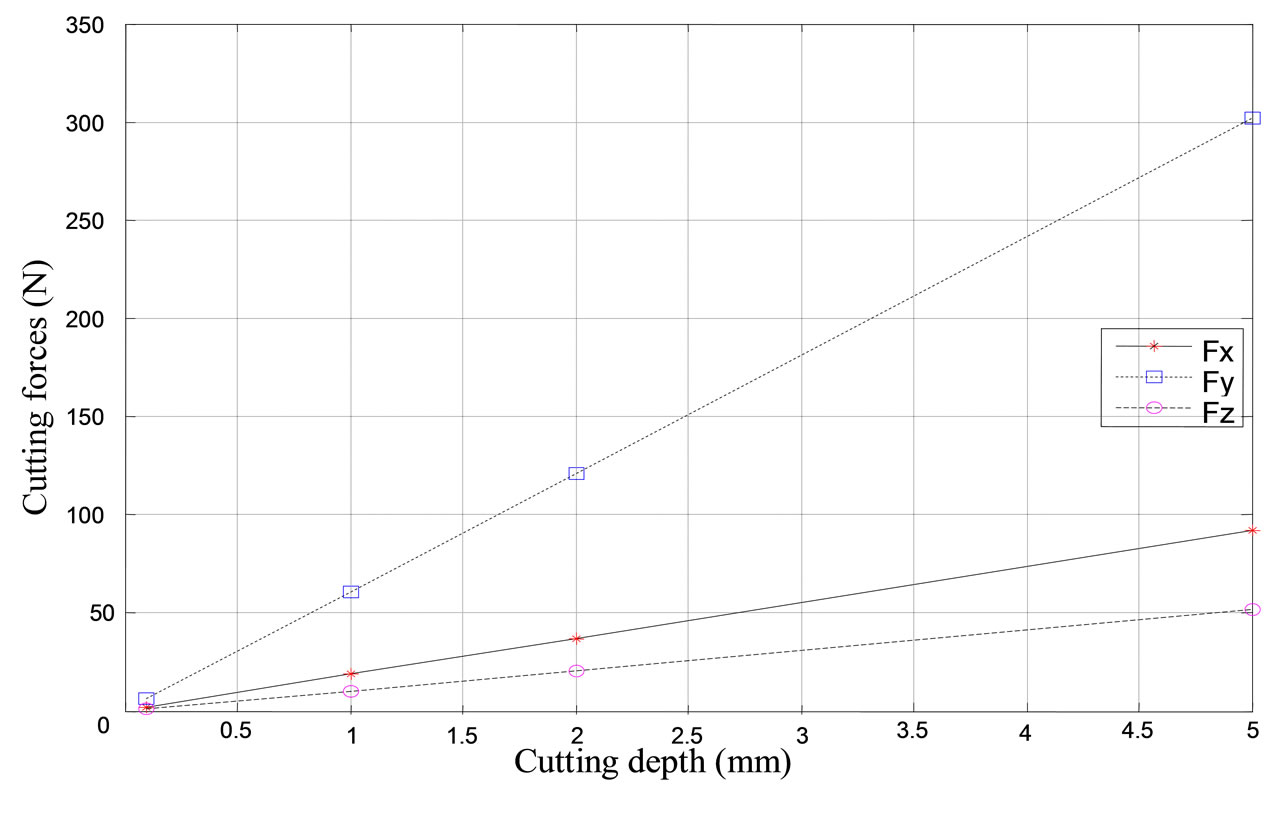
Figure 9. Influence of cutting depth on cutting force f = 0.1 mm/rev; N = 500 rev/min and Z = 6 teeth.
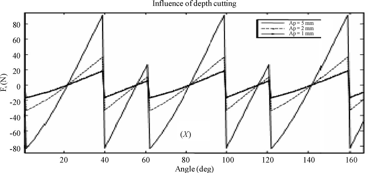
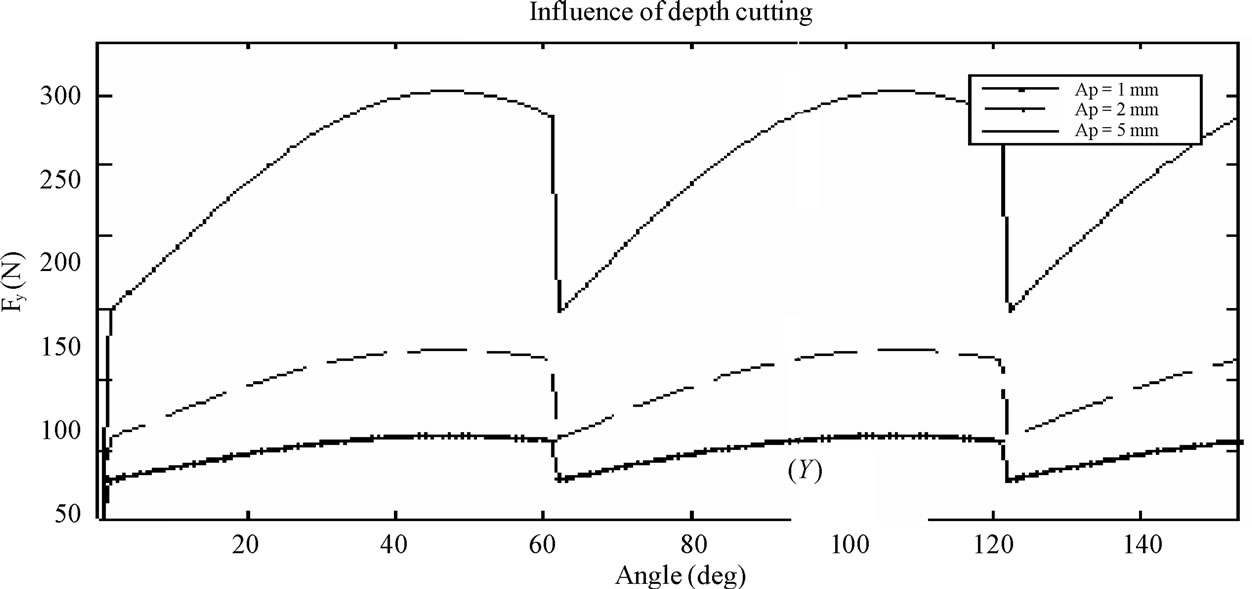
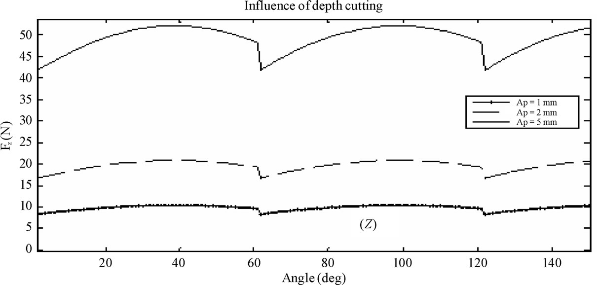
Figure 10. Influence of cutting depth on cutting force.
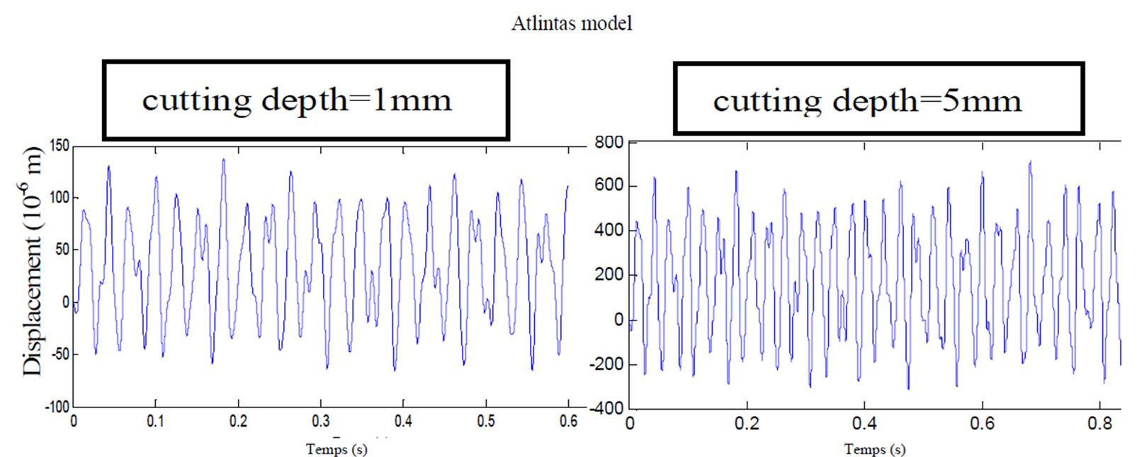
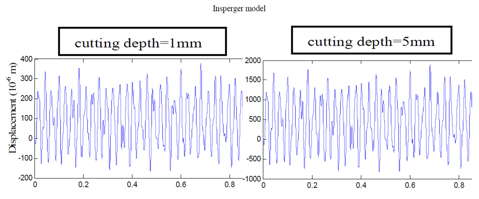
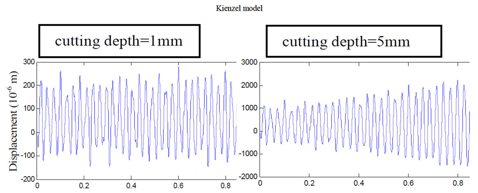
Figure 11. Influence of cutting depth on dynamic response (f = 0.1 mm/rev; N = 500 rpm; Z = 6).
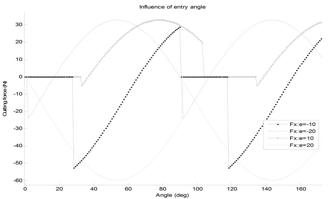
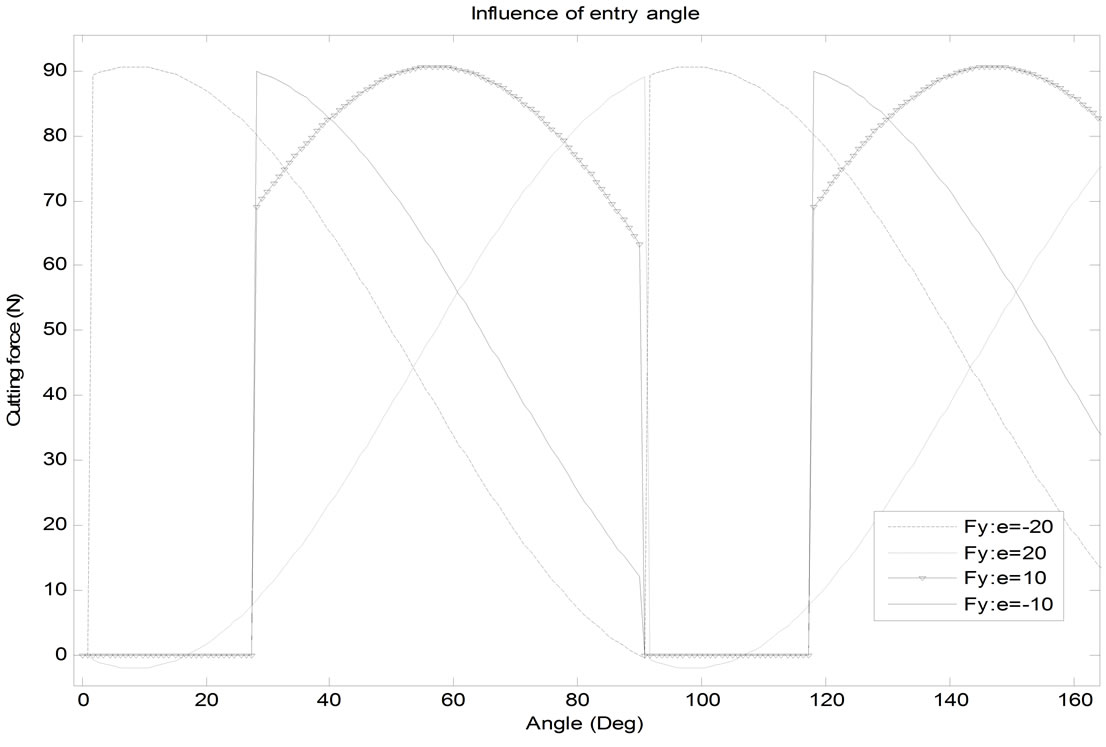
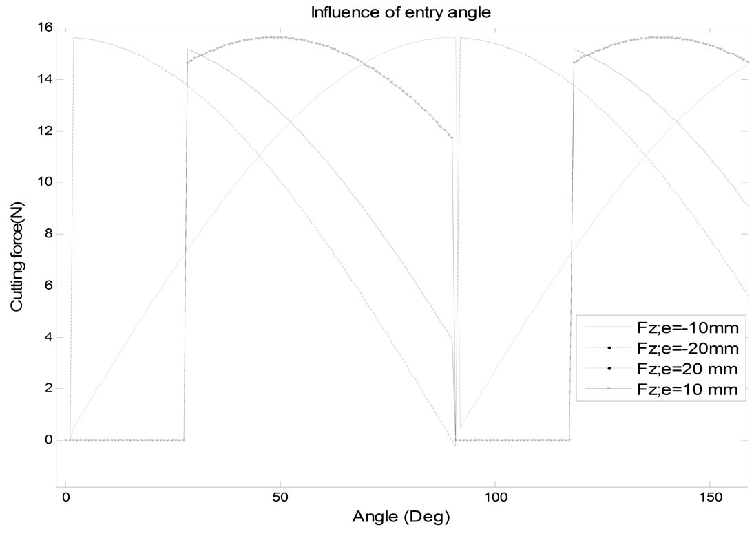
Figure 12. Influence of entry angle on cutting forces.
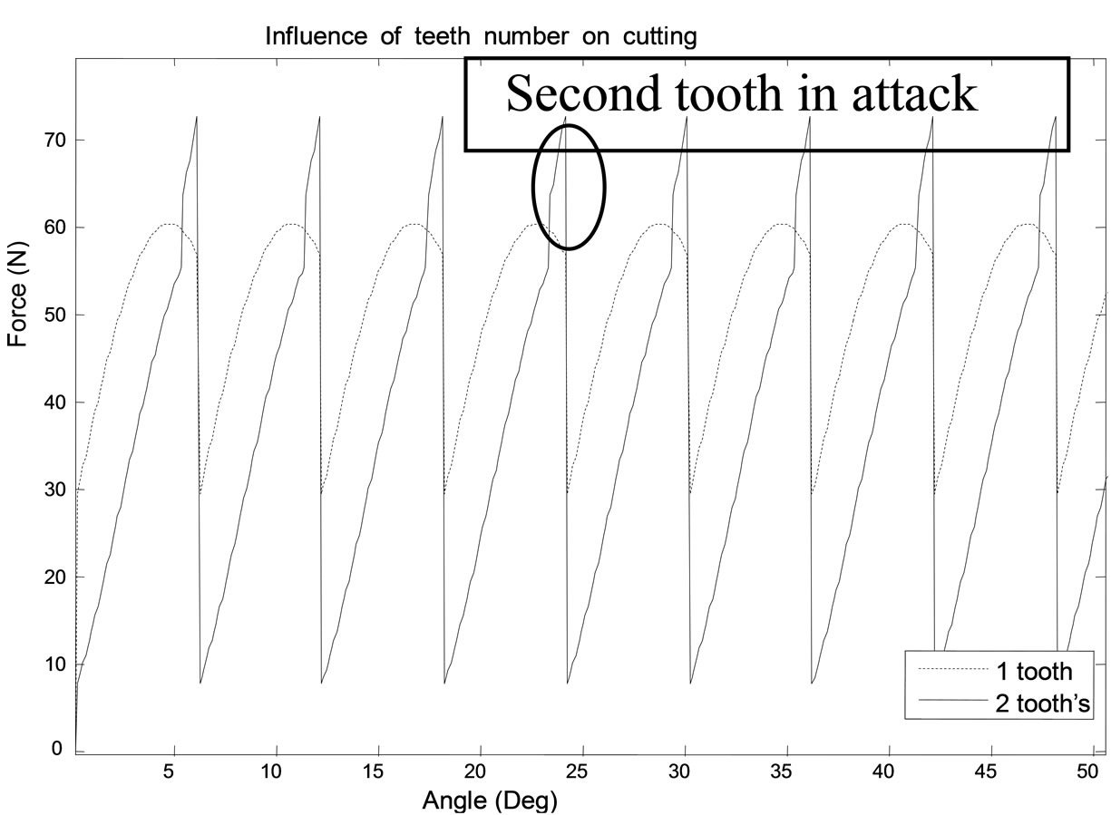
Figure 13. Influence of teeth number on cutting forces.
their value because the summation of forces of two teeth in attack.
Figure 14 proposes the two modes of milling up milling and down milling. Figure 15 gives the results obtained during two simulations carried out under the same cutting conditions, except the mode of selected milling: the first is in configuration of up milling and the second in configuration of down milling.
We remark that for down milling frequency of vibration rises. Besides, amplitude seems to be little changed.
5. Spectral Response
The spectral representation of displacement following
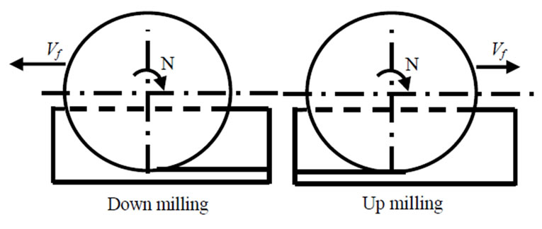
Figure 14. Two modes of milling.
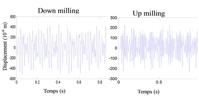
Figure 15. Numerical results for the two modes of milling.
axis X, Y in Figure 16 proves that there are dominant vibrations due to periodical cutting pressure at the frequencies of passage of the teeth (TPF, 2TPF and 3TPF) and the maximum vibration is in the feed direction. In the feed direction (X), simulation shows the unstable frequencies for the cut with approximately 37 Hz, 60 Hz and 85 Hz, which is almost one of the natural frequencies of the system.
TPF: Frequency of teeth passage
FP: Eigen frequency
6. Conclusions
In this work, numerical study is conducted to predict
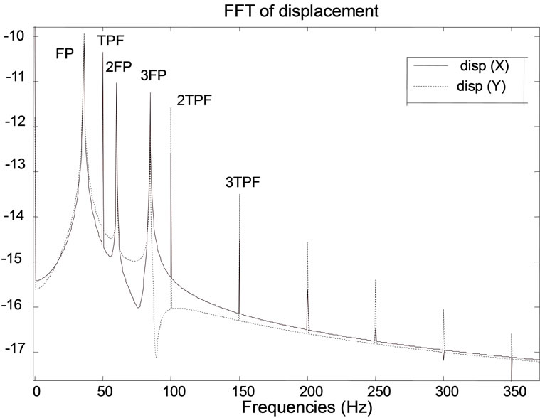
Figure 16. Spectral response.
cutting forces variation according to cutting parameters in milling operation. So, dynamic equation is established using finite element method and projected on the basis of the eigenmodes. The resolution of the obtained equation by numerical method gives dynamic response and cutting force variation. The main objective of this method is to take the influence of machine, tool and part simultaneously. Results showed that most influenced parameters are feed and cutting depth. In fact, clear influence appears on dynamic response for little variation of these parameters. Indeed, simulation reveals that the adopted cutting models have an effect on dynamic response of the system. Besides predicted spectral response of the system machine-tool-part showed that frequency vibrations are due to frequencies of passage of the teeth and eigen frequency of the system.
Finally, modelling milling operations, by finite element method represents a very useful tool for the prediction of the behaviour of the system. So, the need for establishing extensive cutting experi-ments is reduced.
REFERENCES
- S. A. Tobias and W. Fishwick, “A theory of Regenerative chatter,” The Engineer-London, 1958.
- J. Tlusty and M. Polacek, “The Stability of Machine Tools against Self Excited Vibrations in Machining,” International research in production engineering, ASME, 1963, pp. 465-474.
- D. Montgomery and Y. Altintas, “Mechanism of Cutting Force and Surface Generation in Dynamic Milling,” ASME, Journal of Engineering for Industry, Vol. 113, No. 2, 1991, pp. 160-168.
- Y. Altintas, D. Montgomery and E. Budak, “Dynamic Peripheral Milling of Flexible Structures,” ASME Journal of Engineering for Industry, Vol. 114, No. 2, 1992, pp. 137-145.
- E. Budak and A. Altintas, “Modelling and Avoidance of Static form Errors in Peripheral Milling of Plates,” International Journal of Machine Tools and Manufacture, Vol. 35, No. 3, 1993, pp. 459-476.
- E. Budak and Y. Altintas, “Analytical Prediction of Chatter Stability in Milling—Part I: General Formulation,” Journal of Dynamic Systems, Transactions of the ASME, Vol. 120, No. 1, 1998, pp. 31-36.
- Y. Altintas and E. Budak, “Analytical Prediction of Stability Lobes in Milling,” Annals of the CIRP, Vol. 44, No. 1, 1995, pp. 357-362.
- Y. Altintas, “Manufacturing Automation—Metal Cutting Mechanics, Machine Tool Vibration and CNC Design,” Cambridge University, 2000. ISBN-13: 978-0521659734.
- T. Insperger and G. Stépán, “Stability of High-Speed Milling,” Proceedings of the 2000 ASME International Mechanical Engineering Congress and Exposition, No. AMD-241, Orlando, Florida, 2000, pp. 119-123.
- W. T. Corpus and W. J. Endres, “A High Order Solution for the Added Stability Lobes in Intermittent Machining,” in Proceeding of the Symposium on Machining Processes, No. MED-11, 2000, pp. 871-878. Paper number DETC97 /VIB-4021.
- P. V. Bayly, J. E. Halley, B. P. Mann and M. A. Davies, “Stability of Interrupted Cutting by Temporal Finite Element Analysis,” Journal of Manufacturing Science and Engineering, Vol. 125, No. 2, 2003, pp. 220-225.
- M. A. Davies, J. R. Pratt, B. Dutterer and T. J. Burns, “Stability Prediction for Low Radial Immersion Milling,” Journal of Manufacturing Science and Engineering, Vol. 124, No. 2, 2002, pp. 217-225.
- G. Peigné, H. Paris, D. Brissaud and A. Gouskov, “Simulation numérique d’une opération de fraisage à grande vitesse : étude de la stabilité”, 16ème Congrès Français de Mécanique, Nice, 2003.
- B. P. Mann, T. Insperger, P. V. Bayly and G. Stépán, “Stability of Up-Milling and Down-Milling, Part 2: Experimental Verification,” International Journal of Machine Tools & Manufacture, Vol. 43, No. 1, 2003, pp. 35-40.
- B. P. Mann, P. V. Bayly, M. A. Davies and J. E. Halley, “Limit Cycles, Bifurcations, and Accuracy of the Milling Proces,” The Journal of Sound and Vibration, Vol. 277, No. 1-2, 2004, pp. 31-48.
- R. J. Saffar, M. R. Razfar, O. Zarei and E. Ghassemieh, “Simulation of Three-Dimension Cutting Force and Tool Deflection in the End Milling Operation Based on Finite Element Method,” International Journal of the Federation of European Simulation Societies: Simulation Modelling Practice and Theory, Vol. 16, No. 10, 2008, pp. 1677-1688
- M. T. Zaman, A. S. Kumar, M. Rahman and S. Sreeram, “A Three-Dimensional Analytical Cutting Force Model for Micro End Milling Operation,” International Journal of Machine Tools & Manufacture, Vol. 46, No. 3-4, 2006, pp. 353-366.
- W. Y. Bao and I. Tansel, “Modeling Micro End Milling Operations, Part I: Analytical Cutting Force Model,” International Journal of Machine Tool and Manufacture, Vol. 40, No. 15, 2000, pp. 2155-2173.