Intelligent Control and Automation
Vol. 3 No. 3 (2012) , Article ID: 22044 , 4 pages DOI:10.4236/ica.2012.33023
Modeling a Controller for an Articulated Robotic Arm
1Department of Production Engineering, Birla Institute of Technology, Ranchi, India
2Department of Mechanical Engineering, Birla Institute of Technology, Ranchi, India
Email: *rajeev_agra@yahoo.com
Received December 1, 2011; revised May 7, 2012; accepted May 15, 2012
Keywords: Robotic Arm; Proportional Integral Derivative (PID) Controller; Transfer Function; Computed Torque Technique; Atmega 16/32
ABSTRACT
The precise control upon each degree of freedom of a robotic arm is a great challenge in implementing industrial work. This paper aims to design a novel controller for an automated robotic arm. A discrete Proportional Integral Derivative (PID) control technique is being used to replace the complex electronic circuitry, which would greatly reduce the cost and size of the controller. DC motors will be controlled on the basis of Closed-Loop System using an avr (Atmega 16/32) microcontroller. Transfer functions have been derived for mathematical modeling of the system through which the stability of the system can be evaluated prior to fabrication.
1. Introduction
The recent rapid progress in robotic technologies has led to great expectations for robots to be applied in various fields such as industrial robots, guard robots and home robots [1]. Robotic arms find vast applications in several industrial automation processes such as manufacturing tasks, assembly lines etc. [2]. Motion control of a robotic arm can be classified into many categories. Lygorouas et al. [3] developed a computer-controlled light weight mechanical arm. This mechanical arm was a self-contained, autonomous system capable of executing high-level commands from a supervisory computer. The actuators of the joints were permanent magnet type DC motors driven by servo amplifiers via Pulse Width Modulation. Aung [4] designed and implemented a controller circuit based on PIC microcontroller and H bridge circuit to control the motion of a Wheeled Mobile Robot (WMR). He used MATLAB software for the modeling of the total system. Silva [5] applied fuzzy logic at several hierarchical levels of a typical robotic control system. For controlling robotic manipulators, Moosavian [6] used Transpose Jacobian (TJ) control. Arciniegas et al. [7] developed neural network based adaptive control system to control the flexible robotic arm. Tseng [8] developed a DSP based instantaneous torque controller to control the manipulator. Rogers [9] designed a microcontroller circuit for interfacing joint sensor to control robotic arm. In this text a unique computed torque technique is being used to actuate the various joints. Given the dynamic equation of a robotic arm, the basic problem is to determine the various torque/forces to drive all the joints of the arm in real time. This is done in order to track a desired time based trajectory as closely as possible. The motor current/ voltage characteristics and the computed torque are converted into an applied motor current/voltage which actuates the dc motors.
A closed loop PID controller is being used to reduce the overshoot, rise time and the steady state error. A PID controller usually comprises of a Proportional, Integral and Derivative circuitry but here the whole PID controller is implemented through programming which greatly reduces the electronic circuitry as well as cost of the system. This approach also simplifies tuning of the proportional (Kp), integral (Ki) and derivative (Kd) gains. The computed voltage from the error signal is applied to the motor by Pulse Width Modulation (PWM) technique.
A Transfer function is a mathematical expression which relates the input and output variables by using Laplace transform. This can be modeled via MATLAB (SIMULINK) to obtain the various performance characteristics of the whole system which may be in the form of graphs. Here an approximate transfer function is derived considering the parameters such as damping, moment of inertia, gear ratio etc.
The first section gives insight into modeling of system using a suitable transfer function. It is followed by the concepts of Proportional Integral Derivative control. Then, the advantage of implementing a discrete PID controller is highlighted by using an atmega 16/32 bit microcontroller.
2. Transfer Function
The transfer function of a single joint can be well approximated by Equation (1.1) using the following variables:
Va = Armature voltage (Volts)
La = Armature inductance (Henry)
Ra = Armature resistance (Ohms)
θm = Angular displacement of thee motor shaft (Radians)
Jeff = (Jm + n2JL)
Jm = Moment of inertia of the motor referred to the motor shaft (oz.in.s2/rad)
JL = Moment of inertia of the load referred to the load shaft (oz.in.s2/rad)
n = Gear reduction ratio feff = (fm + n2fL)
fm = Viscous friction coefficient referred to the motor shaft (oz.in.s/rad)
fL = Viscous friction coefficient of the load referred to the load shaft (oz.in.s/rad)
n = Gear reduction ratio Ka = Motor torque proportional constant (oz.in/A)
Kb = Proportionality constant between ω (angular speed) and eb (back emf)
Kp = Position feedback gain
θd = Desired angle e(t) = (θd(t) – θ(t)) the error in position
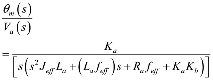 (1.1)
(1.1)
Since the electrical time constant of the motor is much smaller than the electrical time constant, the armature inductance (La) can be neglected.
Hence,
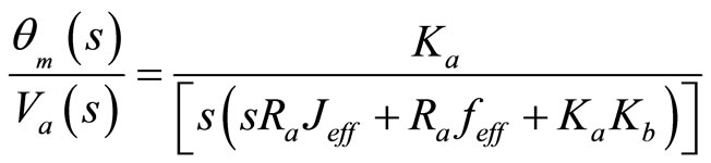 (1.2)
(1.2)
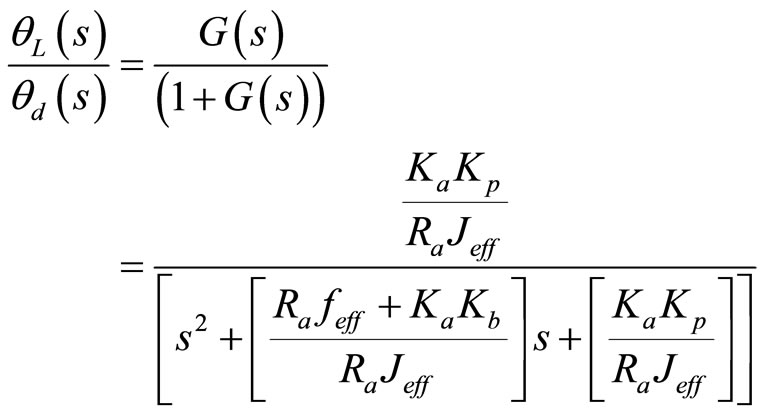
Since the output of the controller is the angular displacement of the joint (θL), therefore it can be written:
 (1.3)
(1.3)
This is an open loop second order system, to improve the response of the system a closed loop Proportional, PD, PI or PID controller can be used. This helps in reducing the rise time and the steady state error. In case of a simple Proportional closed loop control the applied voltage is linearly proportional to the error between the desired and the actual angular displacement of the joint.
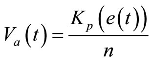 (1.4)
(1.4)
Taking Laplace transform:
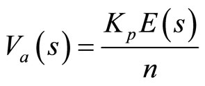 (1.5)
(1.5)
Substituting the value of Va(s) from Equation (1.5) to Equation (1.3) the following equation is obtained:
 (1.6)
(1.6)
After some algebraic manipulation the following equation is obtained:
 (1.7)
(1.7)
Equation (1.7) is a proportional controller for a single joint and is always stable is the system parameters are positive. To increase the system response time and reduce the steady state error an appropriate PD, PI or PID controller can be used.
In case of a PID controller:
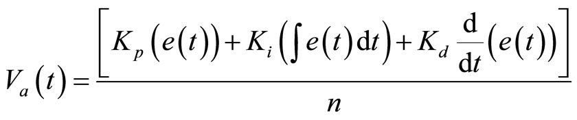 (1.8)
(1.8)
In Equation (1.8) Kp, Ki and Kd are the position, integral and derivative feedback gain respectively.
Taking Laplace transform of Equation (1.8):
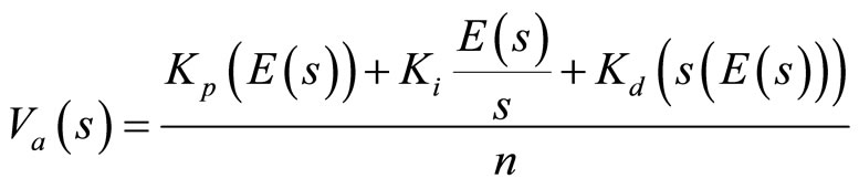 (1.9)
(1.9)
The closed loop transfer function is obtained by performing some algebraic manipulations after substituting the value of Va from Equation (1.9) to Equation (1.3)
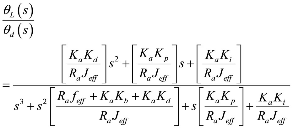 (1.10)
For implementing a PD control Ki should be 0;
And for a PI control Kd should be 0.
The values of Kp, Ki and Kd has to be determined accurately to get the best system performance. The ZieglerNichols method can be used to determine the “Best Fit” value of the three parameters. The Ziegler-Nichols tuning method is a heuristic method of tuning a PID controller. It is performed by setting the “I” (integral) and “D” (derivative) gains to zero. The “P” (proportional) gain, is then increased (from zero) until it reaches the ultimate gain Ku, at which the output of the control loop oscillates with a constant amplitude. Ku and the oscillation period Tu are used to set the P, I, and D gains depending on the type of controller used.
3. Discrete PID Controller
A discrete PID controller reads the error signal, calculates the output and controls the input given to the motor at a given time interval, at the sample period T. The sample time should always be less than the shortest time constant in the system.
4. Algorithm for the Discrete PID Controller
Unlike simple control algorithms, the PID controller is capable of manipulating the system inputs based on the history and rate of change of the signal. This gives a more accurate and stable control method.
Considering Equation (1.8)

Here, e(t)dt can be approximated as  where k varies from 0 to n and
 can be approximated as
  , t = nT and n is the discreet step at time t.
5. Implementation in Atmega 16/32 Microcontroller
Atmega 16/32 is a 16bit avr microcontroller that has inbuilt 8-bit and 16-bit timers. These timers are used to set a pre-specified time interval, and an Interrupt Service Routine (ISR) is executed after every such time interval.
The PID controller uses a structure to store its status and parameters. This structure is initialized in main(??), and only a pointer to it is passed to the Init_PID() and PID() functions.
The PID() function must be called for each time interval T. This is done by a timer which sets the PID_timer flag when the time interval has passed. When the PID_ timer flag is set the main routine reads the desired process value (setPoint) and system process value, calls PID() and gives the output to the control input.
Alternatively the timer interrupt can be activated and the PID() function can be called in that interrupt. After each time interval T the timer interrupt is executed and hence the PID() function is called.
In case the feedback component is an optical shaft encoder then the value of the encoder is taken as an external interrupt in the microcontroller. After that the angle is converted to an equivalent voltage and finally the error signal is computed.
To increase accuracy the P-factor, I-factor and D-factor arescaled with a factor 1:128. The result of the PID algorithm is later scaled back by dividing by 128. The value 128 is used to allow for optimizing in the compiler.
The computed voltage after the PID algorithm is executed is generated by using PWM (Pulse Width Modulation) technique, which can be very easily done using Atmega 16/32.
6. Conclusion
The paper has presented an alternative solution for controlling robotic arm using discrete PID controller technology. The PID controller presented here is a simplified example. The controller should work fine, but it might be necessary to make the controller even more robust (limit runaway/overflow) in certain applications. Adding saturation correction on the integral term, basing the proportional term on only the system process value can become necessary. In calculating the I-factor and D-factor the sample time T is a part of the equation. If the sample time T used is much smaller or larger than 1 second, accuracy for either I-factor or D-factor will be poor.
7. Acknowledgements
We thank The Institution of Engineers (India) for supporting this work through a grant-in-aid. We are also grateful to the Department of Production Engineering, BIT Mesra for providing the required infrastructure.
REFERENCES
- T. A. Salih and O. I. Yehea, “A Novel Control System for Robotics Devices,” Journal of Theoretical & Applied Information Technology, Vol. 28, No. 1, 2011, pp. 48-53.
- P. I. Corke and S. Hutchinson, “A Tutorial on Visual Servo Control,” IEEE Transactions on Robotics and Automation, Vol. 12, No. 5, 1996, pp. 651-670. doi:10.1109/70.538972
- N. Lygorouasjohn, G. Mertziosbasil and C. VoulgarisNicholas, “Design and Construction of a MicrocomputerControlled Light-Weight Robot Arm,” Robotics and Autonomous Systems, Vol. 7, No. 4, 1991, pp. 269-283. doi:10.1016/0921-8890(91)90058-S
- W. P. Aung, “Analysis on Modeling and Simulink of DC Motor and Its Driving System Used for Wheeled Mobile Robot,” World Academy of Science, Engineering and Technology, Vol. 32, 2007, pp. 299-306.
- C. W. de Silva, “Applications of Fuzzy Logic in the Control of Robotic Manipulators,” Fuzzy Sets and Systems, Vol. 70, No. 2-3, 1995, pp. 223-234. doi:10.1016/0165-0114(94)00219-W
- S. Ali, A. Moosavian and E. Papadopoulos, “Modified Transpose Jacobian Control of Robotic Systems,” Automatica, Vol. 43, No. 7, 2007, pp. 1226-1233. doi:10.1016/j.automatica.2006.12.029
- I. Arciniegasjorge, H. Eltimsahyadel and J. Cioskrzysztof, “Neural-Networks-Based Adaptive Control of Flexible Robotic Arms,” Neurocomputing, Vol. 17, No. 3-4, 1997, pp. 141-157. doi:10.1016/S0925-2312(97)00037-4
- K. J. Tseng, “DSP-Based Control of Brushless DC Drives for Direct-Driven Robotic Arms,” Microprocessors and Microsystems, Vol. 19, No. 10, 1995, pp. 581-589. doi:10.1016/0141-9331(96)84159-7
- J. R. Rogers, “Low-Cost Teleoperable Robotic Arm,” Mechatronics, Vol. 19, No. 5, 2009, pp. 774-779. doi:10.1016/j.mechatronics.2009.03.004
NOTES
*Corresponding author.