Materials Sciences and Applications
Vol.4 No.7A1(2013), Article ID:34151,5 pages DOI:10.4236/msa.2013.47A1001
Method of Dimensioning Stress-Strain State of Steel Concrete Plate
![]()
1University of Bamenda, Douala, Cameroon; 2North Carolina Agricultural & Technical State University, Greensboro, USA.
Email: *yamb_bell@yahoo.fr
Copyright © 2013 Emmanuel Yamb, Christian A. Bock Hyeng. This is an open access article distributed under the Creative Commons Attribution License, which permits unrestricted use, distribution, and reproduction in any medium, provided the original work is properly cited.
Received April 14th, 2013; revised May 26th, 2013; accepted June 7th, 2013
Keywords: Stress; Strain; Steel-Concrete; Internal Forces
ABSTRACT
The steel-concrete constructions experience an increased development this last time. The main advantages are that they ensure the economy of materials, energy and labour. The steel-concrete elements allow a rational use of the concrete in the tensile zone, ensure a reduction of the weight of the building, its cost and also reduce the formwork. The calculations carried out by the authors make it possible to establish the dependence between the constraints and the deformations in the principal directions under a biaxial state of stresses, to obtain the expressions of the principal moments, determine the parameters of the deformations of the concrete Eb, Ebi, νb, νbi, obtained through the reduction of the tensile and compressive stresses of the concrete in an isotropic conventional homogeneous state. The expressions of the constraints in the plate are gotten and compared between the theoretical values and the experimental convergence of the results with a variation of less than 8%.
1. Introduction
Recently, it was seen that, there is significant development of external reinforcement of plates that is unification of concrete and openly-located steel plate which functions as reinforcement and jointly work together. This resulted in better technical and economic characteristics of structures in terms of metal intensity used, their input in the resolution of cracks development in the tensile zone of concrete and labor input for their erection. The present article develops fundamental provisions of steel-concrete plates theory which takes into account compliance of the contact between concrete and steel plate.
2. The Stress-Strain State of the Steel-Concrete Plate
2.1. The Dependence between Stresses and Deformations
Theoretical researches are based on the following prerequisites: simple simultaneous loading is considered; concrete is considered to be non-linearly deformed material, conventionally continuous; plate components in horizontal direction are connected by elasto-compliant bonds of shear, and in vertical direction-by absolutely rigid lateral bonds (therefore, the thickness of steel plate does not exceed 1/20 ∙∙∙ 1/100 of plate height); plate height is assumed to be small in comparison with other dimensions. It is supposed, that the plate is loaded only by lateral load.
The dependence between stresses and deformations in the main directions under biaxial stressed state is adopted in the following form (1):
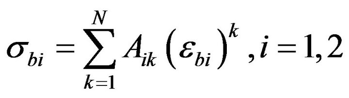 (1)
(1)
where 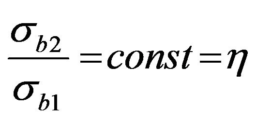 .
.
Coefficients A1k, A2k (k = 1, 2, ∙∙∙, N) are found from the conditions of minimization of squares of stresses deviation obtained in the experiments with specified η, from stresses obtained according to approximating dependencies (1). In the result of processing of H. Kupher’s experimental data [1] coefficient values were obtained for concrete with strength of Rb = (19.0; 32.0; 60.0) MPa at η = (0; 0.2; 0.5; 0.75; 0; −0.25; −0.5; −0.75; −1.0) and corresponding ultimate deformations.
2.2. The Fiber Deformations in Compressed and Tensile Zones
Let us consider small rectangular element cut out of plate as indicated in Figure 1. Suppose that cracks will pass along the areas of the main tensile stresses. In this case when M1 reaches value of Mcrc in the direction of moment M1 action crack is formed, and in the direction of moment M2 action concrete will work without cracks. According to the hypothesis of plane cross sections which holds true for concrete part of cross-section we’ll have:
.,,,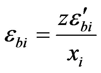 ;
; 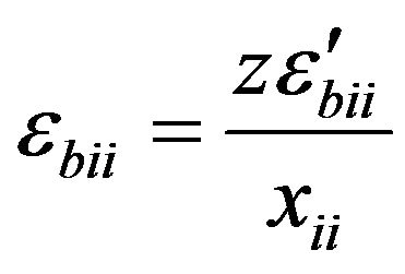
where xi, xii are heights of compressed and tensile zones; ,
,  are fiber deformations in compressed and tensile zones.
2.3. The Bending Moments
The Position of neutral axes is defined by xi values which are to be found from equilibrium condition .
.
From the condition of equilibrium for bending moments we’ll obtain:
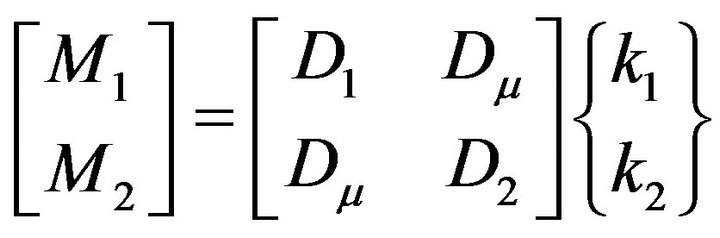 , (2)
, (2)
where
 ;
;
 ;
;
 .
.
As is the unit of length area of plate at; i = 1, 2; j = 2, 1.
Parameters of deformation Eb, Ebi, νb, νbi are obtained through reduction of compressed and tensile concrete to conventionally homogeneous isotropic and stressed state [2] (Yamb et al., 2007). For example, for compressed concrete
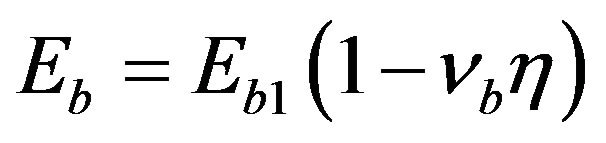 ;
;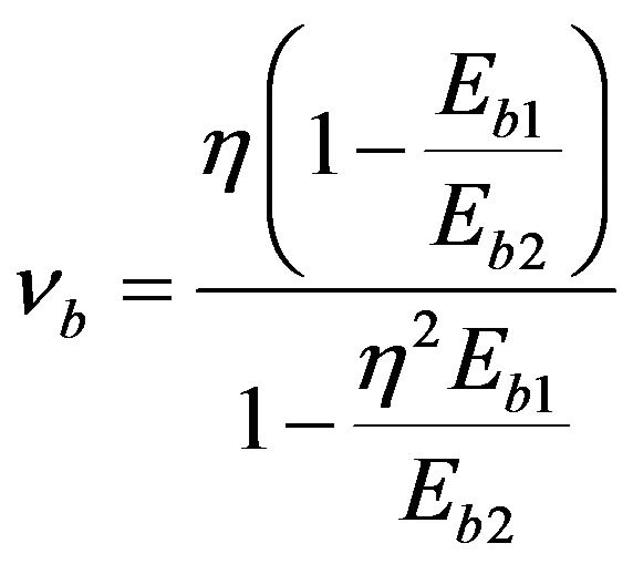 ;
;
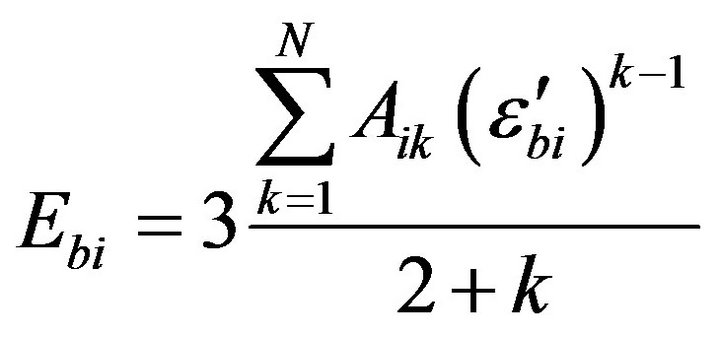 , i = 1, 2.
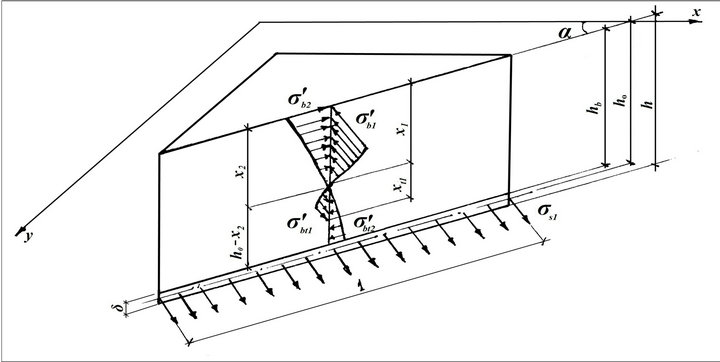
Figure 1. Plate element.
 ,
,  are parameters of steel plate deformation working beyond ultimate elasticity. Impact and concrete is taken into consideration due to introduction of correction factor
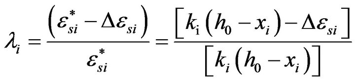 (3)
(3)
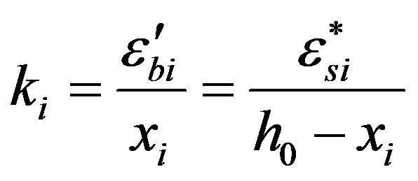
where  are deformations of contact (Figure 2), i = 1, 2.
Making known, transformations of curve tensors and bending moments, we’ll obtain from the expression (2):
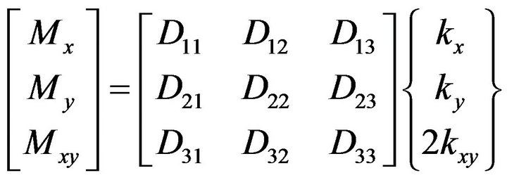 , (4)
, (4)
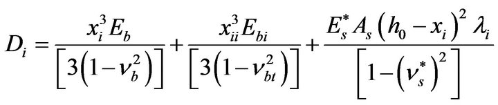
where
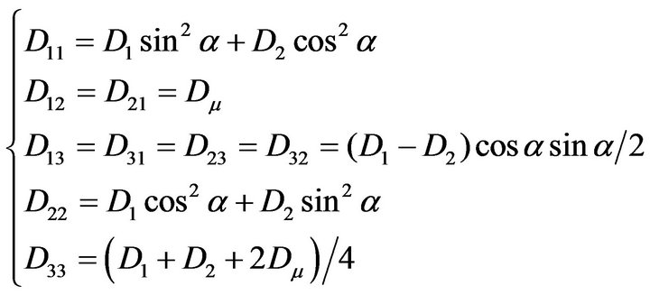 (5)
(5)
2.4. The Stresses
Making use of equilibrium condition of plate element, we’ll obtain the necessary number of equations for solution of problem on stress-strained state of steel-concrete plate.
Rigidity coefficients from Equation (4) are defined in accordance with the plate working stage, degree of stressed state with deformations on the contact taken into account. The following stages can be distinguished here: elastic, elastoplastic without cracking, elastoplastic with cracking.
The beginning of any of the stages and rigidity of plate before crack formation is defined according to [3,4]. The moment of crack formation Mcrc is defined for the strip of steel-concrete plate of unit width with non-linear deformations in tensile concrete zone taken into account. If we suppose that compliance of shear bonds is elastic, we’ll obtain
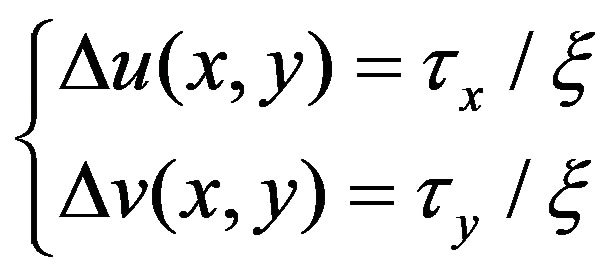 (6)
(6)
where Δu(x,y) and Δv(x,y) are differences, of longitudinal displacements on both sides of the contact. τx and τy are contact forces. ξ is a coefficient of joint rigidity which is to be defined experimentally.
On differentiation of (6), we’ll obtain
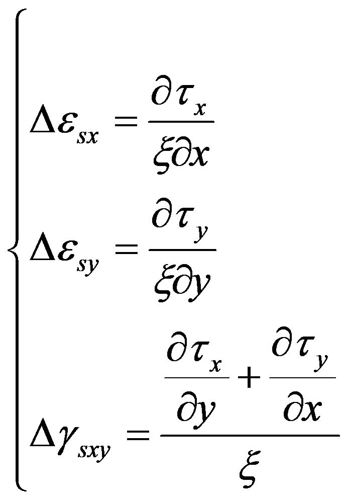 (7)
(7)
For definition of contact forces, let us consider equilibrium of a small element with dimensions dx, dy, δ, cut out of steel plate (Figure 3).The results we’ll obtain are:
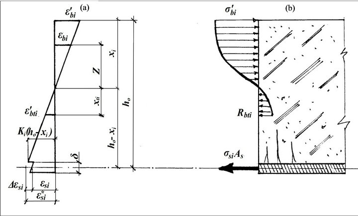
Figure 2. Deformations (a) and stresses (b) of the contact between plate reinforcement and concrete.
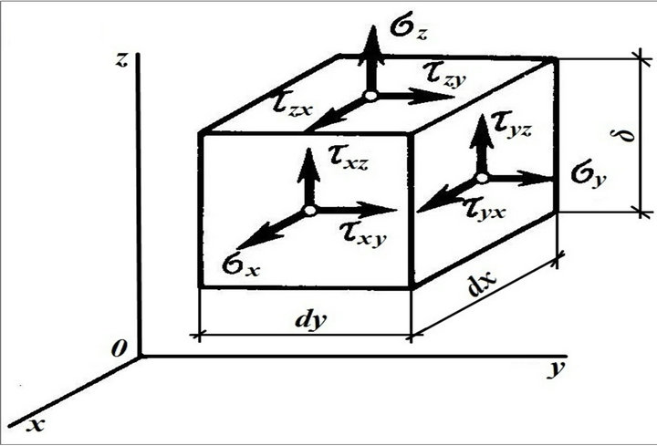
Figure 3. Steel plate element.
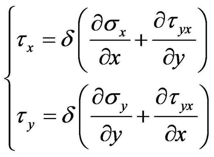 (8)
(8)
with (7) and (8) taken into account we’ll obtain the expressions for contact deformations in the orthogonal system of coordinates
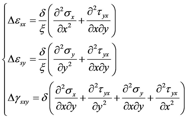 (9)
(9)
We will have the following from the direction of the main axes:
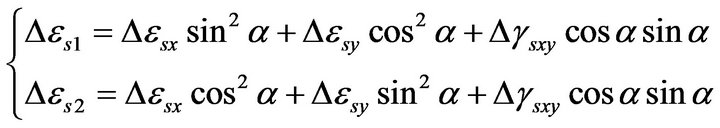 (10)
(10)
Numerically, a suggested solution is realized by the method of finite differences under step-by-step loading of the plate. Substituting of differential operators central and unilateral difference operators of the same order with approximation error 0 [h2].
At the first step of loading at the very beginning calculation for the plate with absolutely rigid shear bonds (λi = 1, i = 1, 2) is carried out. Linearization of non-linear side of the problem is affected in the process of successsive approximations, the variable parameters of which are rigidities Dij (5) in each point. The process of successive approximations is going on until reaching satisfactory convergence along flexures, after which the values of stresses in the steel plate σsx (I,J), σsy (I,J), τsxy (I,J) obtained at λi = 1 are approximated in the following form:
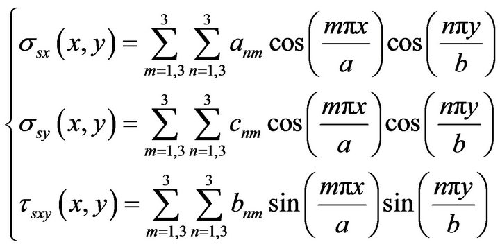 (11)
(11)
where a, b are plate dimensions in plan; anm, cnm, bnm are unknown coefficients defined by the method of least squares.
Operations (9) and (10), with (11) taken into account, enable us to find parameters λi (3) in accordance to which rigidities are specified (5) and new solution is searched for at a given step of loading which takes into account compliance of contact between steel plate and concrete. In some points of the plate relative deformations of steel plate are equal to zero (ki = 0) while relative shears are not equal to zero (and vice versa). For these cases the expression (3) is not valid (in practical calculations conventionally assume λi = 1). In this connection the presented approach to accounting of joints compliance can be considered acceptable for steel-concrete plates which have weakly compliant shear bonds.
For the next step of loading rigidities are calculated in accordance with deformed state obtained in the last iteration of the prior step taking corresponding values of λi into consideration as shown in Table 1.
3. Conclusions
To check up if the calculations hold true, the results were compared with the data obtained in the test with steelconcrete plates of 50 mm thickness from the concrete of Rb = 40 MPa strength on the supporting outline of 980 × 980 mm.
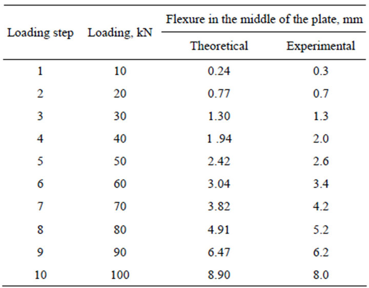
Table1 1. Comparison of experimental and theoretical values of plate flexures with grid MFD 5 × 5.
The plate was reinforced with plane plate of δ = 1 mm thickness from steel with physical ultimate yield of 230 MPa. Initial values of concrete and steel elasticity modulus Eb = 3.3 × 10⁴ MPa and Es = 2.1 × 10⁵ MPa. Jointing of steel plate with concrete was made with inclined loop anchors and its rigidity was ξ = 8 × 10⁵ t/m3. The loading was transferred to the plate through a die of 180 × 180 mm size in the middle of the plate (see Table 1).
Carrying capacity of steel-concrete plate is defined by the following factor which is available in some point of the finite-difference grid: concrete strength, steel strength and strength of the contact between concrete and steel.
Thus, the developed mathematical body allows taking into consideration the development of anisotropic properties of steel-concrete plate resulting from cracks formation and non-linearity of concrete deformation as well as compliance of the contact between plate reinforcement and concrete.
The results obtained can be used for calculation of steelconcrete floors in industrial structures.
REFERENCES
- H. K. Kupher Gerstle, “Behavior of Concrete under Biaxial Stresses,” Proceedings of the American Society of Civil Engineers/Journal of the Engineering Mechanics Division, Vol. 99. No. 4, 1973, pp. 853-866.
- E. Yamb. A. G. Yuriev and L. A. Pachenko, “Calculation of Steel-Concrete Plates Reinforced on one Face,” Vol. 2, VESNIK BGTU, Belgorod, 2007, pp. 29-31.
- N. I. Karpenko, “The Theory of Deformation of Reinforced Concrete with Cracks,” Stroyisdat, Moscow, 1976, 208 pp.
- V. M. Bondarenko and S. V. Bondarenko, “Engineering Methods of Non-Linear Theory of Reinforced Concrete,” Stroyisdat, Moscow, 1982, 287 pp.
Nomenclature
The following symbols are used in the paper.
• E: young modulus, MPa
• D: coefficient of rigidity, N∙mm/mm
• M: bending moment, kN∙m
• ε: strain, %
• γ: shear angle, %
• σ: normal stress, MPa
• τ: tangential stress, MPa
• ν: Poisson coefficient
• δ: thickness of the steel sheet, mm
NOTES
*Corresponding author.