Materials Sciences and Applications
Vol.4 No.4(2013), Article ID:30559,8 pages DOI:10.4236/msa.2013.44026
Minimization of Stock Weight during Close-Die Forging of a Spindle
![]()
Department of Material Science, Dalarna University, Borlänge, Sweden.
Email: hss@du.se
Copyright © 2013 Hamzah Ssemakula. This is an open access article distributed under the Creative Commons Attribution License, which permits unrestricted use, distribution, and reproduction in any medium, provided the original work is properly cited.
Received September 11th, 2012; revised November 24th, 2012; accepted January 10th, 2013
Keywords: Close-Die Forging; Forging Load; Material Flow; Effective Strain Distribution
ABSTRACT
In this paper, Finite Element method and full-scale experiments have been used to study a hot forging method for fabrication of a spindle using reduced initial stock size. The forging sequence is carried out in two stages. In the first stage, the hot rolled cylindrical billet is pre-formed and pierced in a closed die using a spherical nosed punch to within 20 mm of its base. This process of piercing or impact extrusion leads to high strains within the work piece but requires high press loads. In the second stage, the resulting cylinder is placed in a die with a flange chamber and upset forged to form a flange. The stock mass is optimized for complete die filling. Process parameters such as effective strain distribution, material flow and forging load in different stages of the process are analyzed. It is concluded from the simulations that minor modifications of piercing punch geometry to reduce contact between the punch and emerging vertical walls of the cylinder appreciably reduces the piercing load. In the flange chamber, a die surfaces angle of 52˚ instead of 45˚ is proposed to ensure effective material flow and exert sufficient tool pressure to achieve complete cavity filling. In order to achieve better compression, it is also proposed to shorten both the length of the inserted punch and the die “tongues” by a few mm.
1. Introduction
A forging company in the middle of Sweden designs, manufactures, and distributes forged and machined components for the heavy truck industry and engineering industry. Its products include among others rear axle components such as spindle, transmission components and other components such as gears, couplings, side bolts, and engine components. The company also forges and machines cylinder components, boring bits, and twist lock pins for container lifting. To manufacture the spindle, Figure 1, the starting stock is a rolled cylindrical billet weighing about 22 kg which is upset forged in a closed die. It’s then subjected to a series of different forgings and later machined to the final geometry which weighs about 13 kg. This manufacturing route is not cost effective since it leads to about 22% of the initial weight as waste. In addition, the flange which is the critical part of the components, is machined rather than forged.
Several researchers have studied forging using FEanalysis in both 2D and 3D versions [1-4]. Conor McCormack and John Monagham analyzed an entire forging sequence of a complex component of spline shape using Deform [5]. Workpiece distortions during the process were analyzed and areas prone to fracture were identified. Nikolai Biba et al. showed the advantages of using FEM to analyze forging processes [6]. Using Deform 3D, Young-Sang Na et al. have predicted the micro structural evolution in blade forging [7].
The company is investigating alternative methods of forging the component in two stages. In the proposed method, the starting stock is a cylindrical billet weighing about 17 kg which is heated in induction furnace at 1170˚C and upset forged in a closed die. While still in the same die, it is then pierced using a spherical nosed cylindrical punch to within 20 mm of its base. During piercing the punch is lubricated by dipping it in the water-graphite mixture while the die is sprayed with the same lubricant. The maximum available press load is 1000 ton. In the second and final stage the resulting cylinder is placed again in a die furnished with a flange chamber. With the punch inserted first in the cylinder to maintain the inner radius, the upper die is moved downwards upsetting the cylinder hence forming the flange in
 (a)
(a)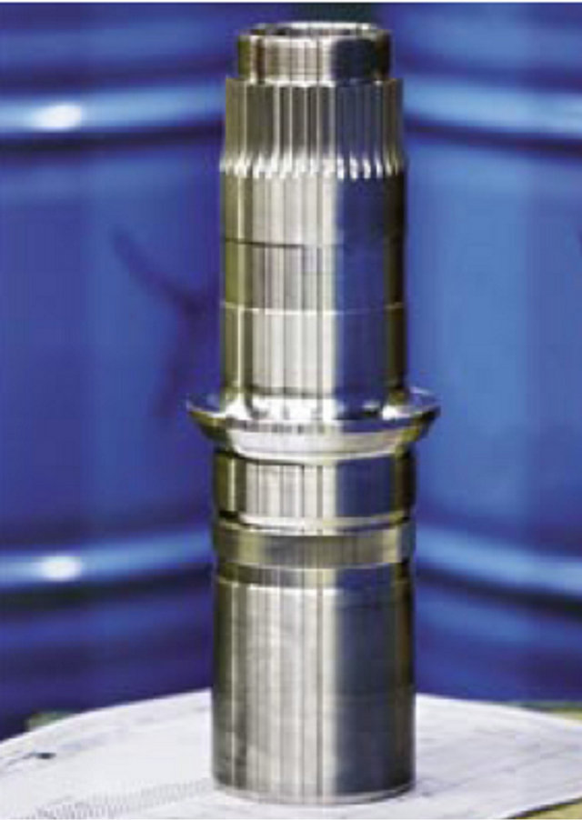 (b)
(b)
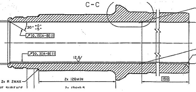
Figure 1. (a) Section of the rear axle part showing the geometry of the flange; (b) Finished spindle.
the closed chamber. In the test carried out, it was shown that the piecing press stopped before reaching the final geometry needed. There was insufficient filling of the die cavity and tendencies of friction welding between the punch and workpiece were observed. In the third and final stage, the full scale trials showed a tendency for the cylinder to buckle and form material fold in the chamber area.
The purpose of the project is to analyze the problem of die filling, press load during piercing and material flow with respect to punch and die design.
2. Experiments
Process Description
A rolled cylindrical billet measuring 95 mm in diameter and 203 mm in height, is heated in a furnace to 1170˚C and upset-forged in a closed using an upper anvil with a protrusion as shown in Figure 2(a). The die is kept at around 200˚C. This pre-forming step is mainly to give the billet the right geometry for the next stage in forming. While still in the same die, the workpiece is pierced using a spherical nosed cylindrical punch to within 20 mm of its base. In piercing the die is designed to allow two different wall thicknesses (reductions) i.e. thinner at the lower part and thicker wall at the upper part of the cylinder. The full-scale trials that were carried out showed that the punch in Figure 2(b) stopped prematurely, i.e. before the cylinder had attained its full height. In Figure 2(c), there was incomplete filling of the die cavity in the chamber area in and a tendency of buckling and formation of material lap.
 (a)
(a)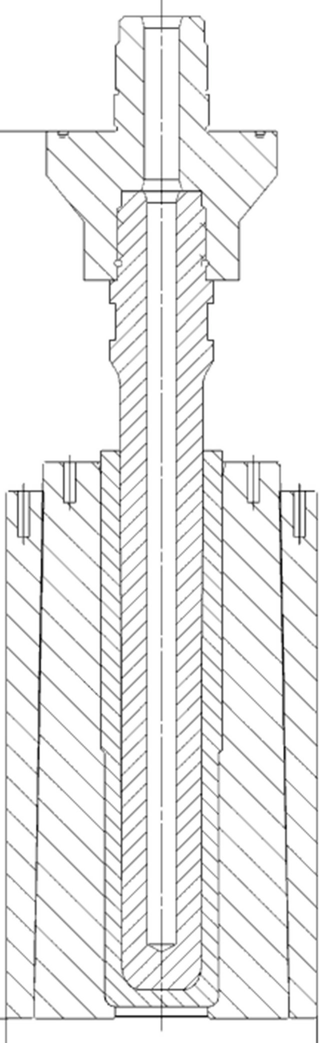 (b)
(b)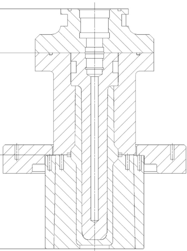 (c)
(c)
Figure 2. (a) Upsetting of the initial billet in a closed die; (b) Piercing in a closed die; (c) Flange forming in a closed die.
3. Simulations
The commercial FE-code Q-form 2D was used to simulate the forging process. Tool and workpiece geometries were generated by solid edge and imported into the code. Remeshing is fully automatic and performed by an automatic meshing generator (AMG). Material data used for the simulation is obtained through experiment and literature survey. Flow stress data for the alloy in question is entered in the code as the following general expression σ = (σ, ε,  , T) where, σ, e,
  , T represent the flow stress, effective strain, effective strain rate and temperature respectively. Other input data is shown in Table 1. Table 2 shows the chemical composition of the alloy analyzed.
During upsetting, the die is lubricated by spraying it with a graphite-water mixture.
In piercing both the punch and the die were lubricated with the same mixture. To get reliable results considering strain and temperature distributions, the friction factor used in these operations is determined by inverse analysis. An initial friction factor used in the FE-simulation was adjusted by comparing results of peak press load obtained in the simulation with measured values from the full-scale experiments. A schematic figure showing how the friction factor is determined is presented in Figure 3. In this way a friction factor of m = 0.5.
4. Results
4.1. Upsetting
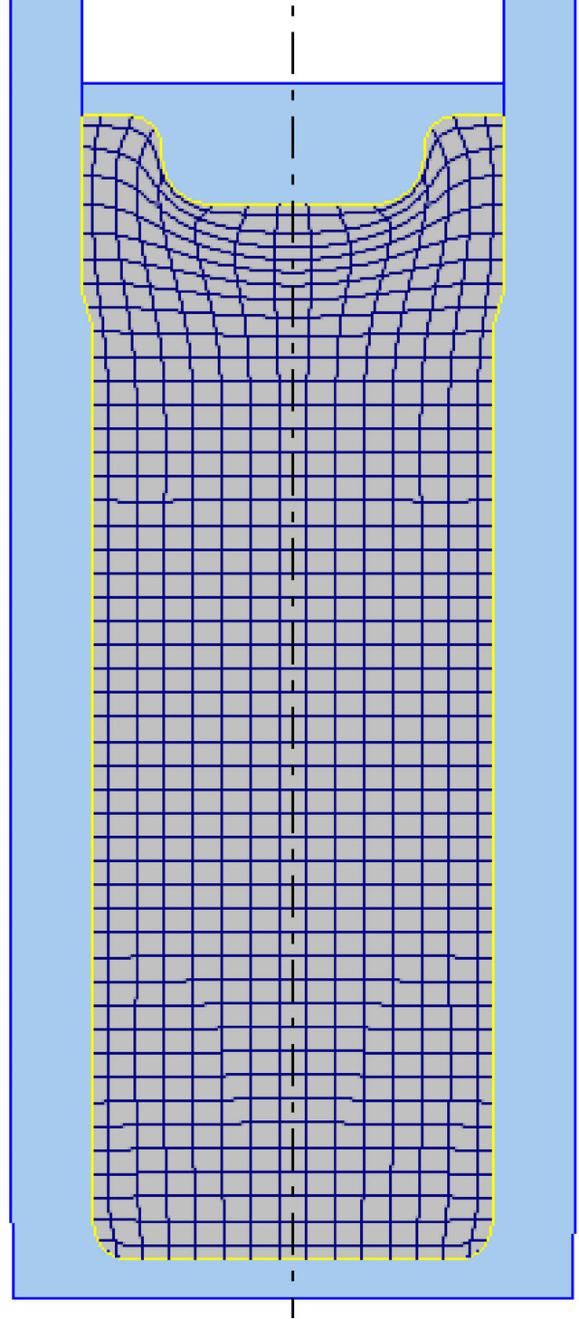
During upsetting, the Deformation is localized. This is shown clearly by square grid distortions in Figure 4(a). Deformation takes place only in an area just immediately under the punch. The rest of the workpiece is largely unaffected by the action of the anvil. The die is fully filled. The load-displacement curve is shown in Figure 4(b). The load is law and remains almost constant during a large portion of the upsetting process. It however rises steeply towards the end of the upsetting process. The steep rise is consistent with filling of a closed die. The peak load is only about 350 ton.
Table 1. Input data for simulation.
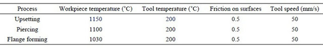
Table 2. Chemical composition [wt%].

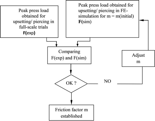
Figure 3. Determination of friction by inverse analysis.
 (a)
(a)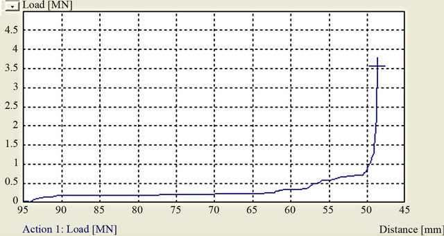 (b)
(b)
Figure 4. (a) Simulated upsetting; (b) Load displacement curve for the process.
4.2. Piercing
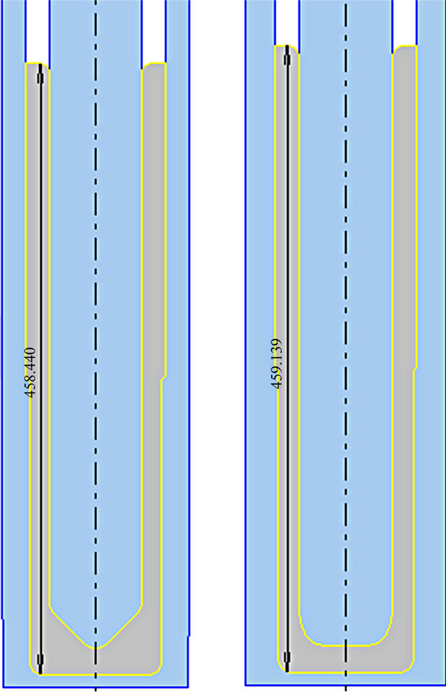
Piercing was carried out according to 2(b) above. The die design allows two different wall thicknesses in the emerging cylinder. Two punch geometries, a spherical nosed and a flat one are analyzed. Simulation results are shown in Figures 5(a) and (b). Corresponding load displacement curves are shown in 5(c) and 5(d). Piercing with a spherical nosed punch begins with a low load according to Figure 5(c). At a penetration depth of about 65 mm, the load increases steeply. This increase is partly due to higher reduction (thin wall thickness) and partly due to increasing workpiece surface which comes in contact both with the vertical wall of die and the punch. As for the flat punch Figure 5(d), the load increases steadily right from the beginning to end at 1300 ton at full penetration. The horizontal doted lines in divides into two directions the left and the right one. At this penetration depth the cylinder height is only about 414 mm. Consequently the available press load is insufficient to complete the piercing process.
4.3. Formation of Flange
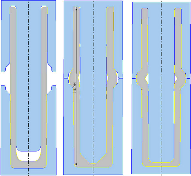
According to Figure 2(c) above, the flange is formed when the cylinder is placed in a die. A punch is inserted in the cylinder to maintain the inner diameter. The surface of the upper die is then used to upset forge the cylinder to form the flange. Simulation results of the process are shown in Figures 6(a)-(c). It’s clear that the cylinder buckles in the chamber region due to anon-conducive aspect ratio, i.e. thin wall thickness compared to the height of the cylinder. The compressive stress is applied only in one direction and without a reactive radial stress in the chamber region; the thin wall cannot withstand the vertical compressive stress. The result is buckling which with continued compression eventually leads to material fold. The simulation results also show that if the inserted punch is spherical the cavity is less filled than when a flat punch is used. With this die design, it is therefore not possible to create compressive stresses in the radial direction to avoid buckling.
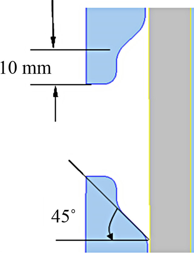
In order to avoid material lap in the flange region, it is necessary to modify the die as shown in Figures 7(a) and (b). A die angle of 52˚ instead of 45˚ is proposed and the die “tongue” is reduced by 4 mm.
4.4. Analysis of Material Flow
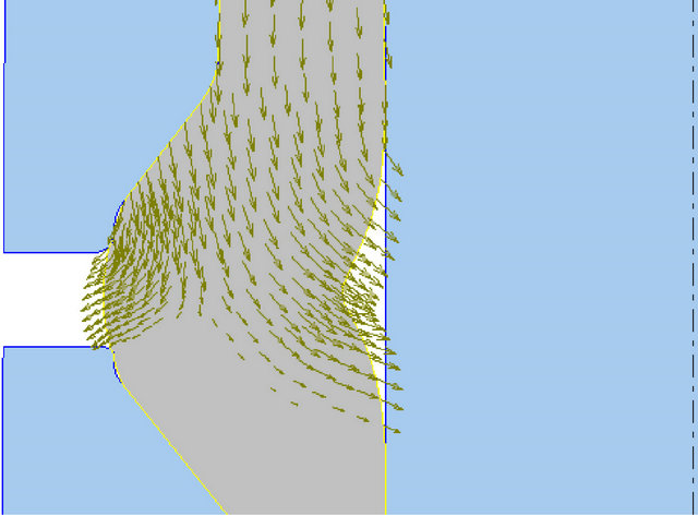
An analysis of material flow during formation of the flange was carried out and the simulation results are shown in Figures 8(a)-(c). At the beginning material flow is localized only in the upper part of the workpiece.
 (a)
(a)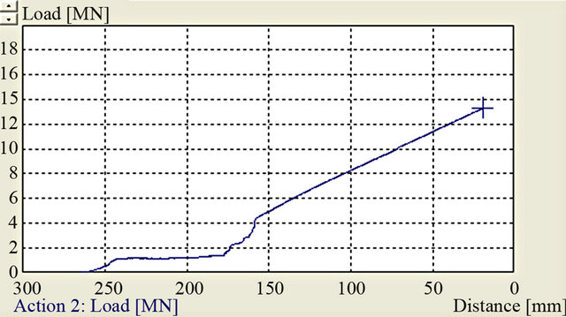 (b)
(b)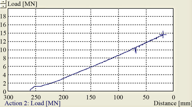 (c)
(c)
Figure 5. ((a), (b)) Simulated piercing using spherical and flat punch; ((c), (d)) Corresponding load displacement curves.
The lower part remains stationary and unaffected by the compression. Almost all the material streams to the left as shown by the velocity vectors in Figure 7(a). At a later stage of the compression, Figure 7(b), the material flow divides into two directions the left and the right one. This happens when the surface A of the die, Figure 6(b) is in full contact with the workpiece. The tool pressure generated by the surface forces the material to flow to the right filling the void between the punch and the workpiece. The earlier in the process this happens the greater the possibility of avoiding material fold. With a 45˚-angle tool the pressure is exerted a bit later in the process when the buckling angle has become acute. In such a situation material fold is then unavoidable. Figures 8(a)
 (a) (b) (c)
Figure 6. Upsetting of the cylinder and formation of flange: (a) Before; ((b), (c)) After compression.
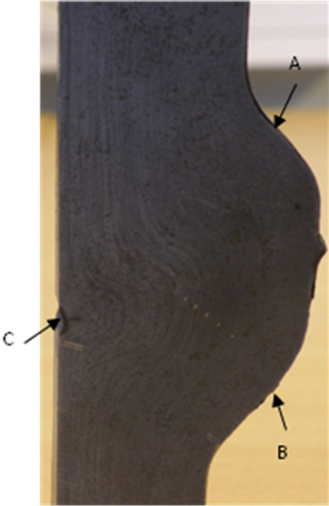
and (b) show the results of full-scale trials. It is evident from the peripheral of the cross-section in 8(a) that the die profile did not have the same tool angle at A and B. This may have resulted in the equatorial material fold at C which is still clearly seen even in Figure 8(b). A microscopic examination of the equatorial region Figure 8(c), reveals that the fold still extends deep in the wall of the component due to none compliance of the recommended die angle of 52˚.
Figure 10(a) shows the accumulated effective strain distribution and the geometry of the final product. The die cavity in the flange region is completely filled with no sign of a fold. As regards the effective strain, the distribution is highly inhomogeneous with a range of 0.01 ≤ ε ≤ 8.5. The upper and lower parts of the workpiece are the least deformed with effective strain levels in the range of 0.01 ≤ ε ≤ 1. The effective strain increases inwardly across the wall thickness. The most deformed is the inner surface of the workpiece which has reached a strain level of 8.5. This strain profile is consistent with the distribution expected from a piercing operation. The most critical part, the flange, has been fully deformed. The strain interval in the flange is 5.5 ≤ ε ≤ 6.5.
Forging process introduces directionality in the metal structure which if controlled properly can enhance resistance to metal fatigue. Flow lines in Figure 10(b) are reminiscent of the flow lines observable on the cross section surface of Figure 9(a) depicting material directionality
 (a)
(a)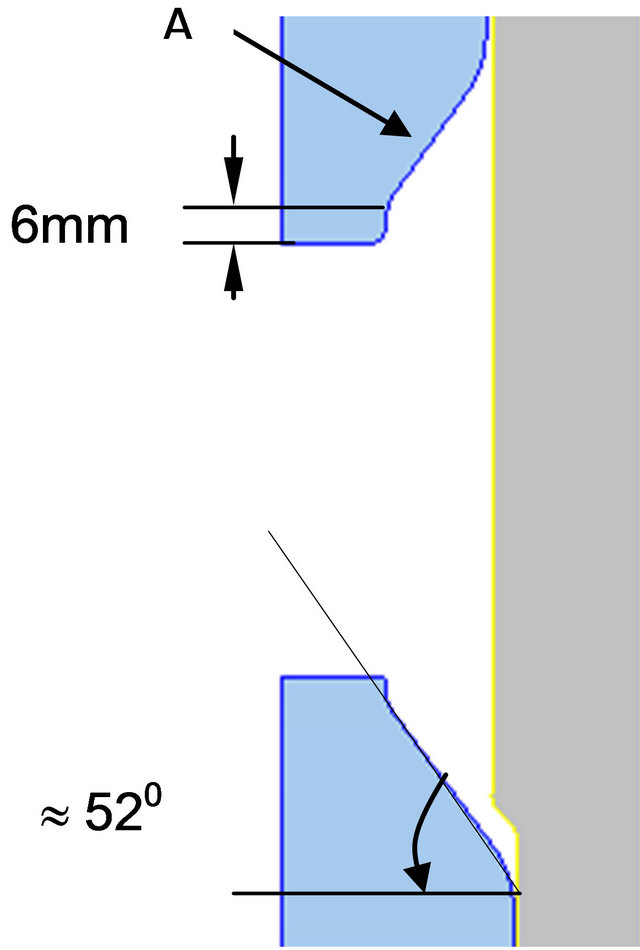 (b)
(b)
Figure 7. (a) Die geometry in the flange region; (b) Proposed modifications.
 (a)
(a) (b)
(b)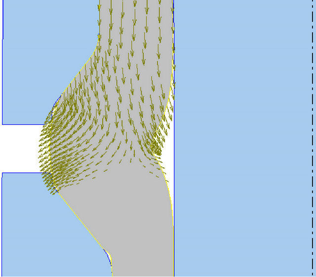 (c)
(c)
Figure 8. Material flow at different stages of flange formation.
 (a)
(a)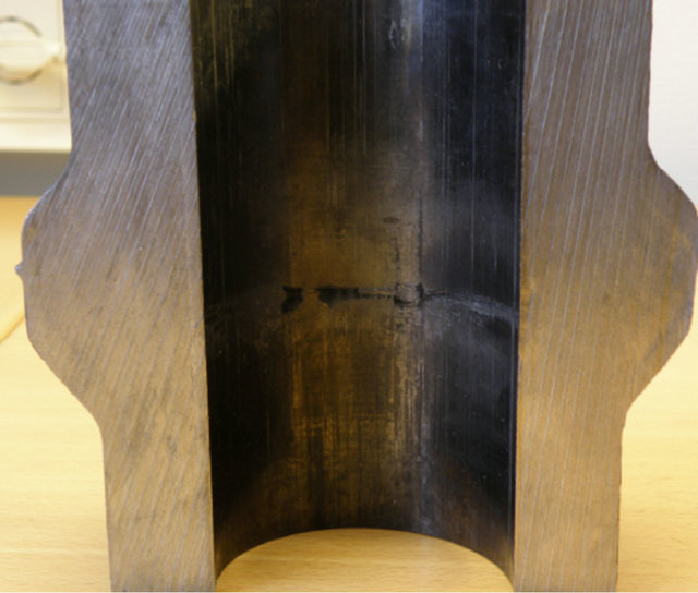 (b)
(b) (c)
(c)
Figure 9. Results of full scale trials: (a) Cross section showing the profile of the die; (b) Material fold along the equatorial region of the workpiece; (c) Micrograph showing the extent of the fold.
 (a)
(a) (b)
(b)
Figure 10. (a) Effective strain distribution; (b) Flow lines in the final product.
in the workpiece.
5. Discussion
The alternative forging process using less initial stock weight is possible but with minor modifications. The piercing process results generally in high strain levels in critical areas of the workpiece. Given that the spindle is subjected to high stress in service, fully deformed parts are desirable. However the process requires high press loads. From Figures 4(a) and (b) it is evident that the peak load required is 300 ton higher than the maximum available press load. Modifying the punch geometry to minimize the contact between the punch and the vertical wall of the emerging cylinder will appreciably bring down the press load.
Material flow during flange formation is critical. To form the flange without risk of material fold, the tool angle for optimal material flow in the furnished chamber has been calculated to approximately 52˚ instead of 45˚. This improves material flow and creates sufficient tool pressure to lead the material in the right direction and avoid material fold.
6. Conclusions
The alternative forging concept for manufacturing the spindle by less initial stock weight developed by the company has been simulated by means of a commercial code Q-form 2D/3D. It is concluded that piecing the workpiece in a closed die is an effective method to deform the metal to high strains under a compressive atmosphere. However the process requires high press loads. The peak load is 1300 ton yet the maximum available press load is 1000 ton. To reduce this load, the piercing tool (punch) geometry should be modified to minimize contact between the punch and the emerging cylinder. Bigger draft angles on the vertical walls of the die may as well help in this regard.
In order to successfully forge the flange, the die angle in the flange chamber should be made steeper to about 52˚. This creates sufficient tool pressure to alter the material flow and avoid material lap. The simulated results show high strains in the flange, complete cavity filling without the risk of material lap/fold in the equatorial region of the workpiece.
7. Acknowledgements
The author is indebted to Triple Steelix for financial support and in particular to Jesper Christian for fruitful discussions.
REFERENCES
- E. M. Mielnik, “Metal Working Science and Engineering,” McGraw-Hill, Inc., New York, 1991.
- S. Kobayashi, S. Oh and T. Altan, “Metal Forming and Finite Element Method,” Oxford University Press, New York, 1989.
- T. Altan, S. Oh and H. Gegel, “Metal Forming Fundamentals and Applications,” American Society for Metals, Ohio, 1983.
- P. Hartley, I. Pillinger and C. Sturgess, “Numerical Modelling of Material Deformation Processes, Research, Development and Applications,” Springer-Verlag, Berlin, 1992. HUdoi:10.1007/978-1-4471-1745-2U
- C. McCornmack and J. Monagham, “2D and 3D Finite Element Analysis of a Three Stage Forming Sequence,” Journal of Material Processing Technology, Vol. 127, No. 1, 2002, pp. 48-56. HUdoi:10.1016/S0924-0136(02)00254-6U
- N. Biba, S. Stebounov and A. Lishiny, “Cost Effective Implementation of Forging Simulation,” Journal of Material Processing Technology, Vol. 113, No. 1-3, 2001, pp. 34-39. HUdoi:10.1016/S0924-0136(01)00616-1U
- Y.-S. Na, J.-T. Yeom, N.-K. Park and J.-Y. Lee, “Simulation of Microstructure for Alloy 718 Blade Forging Using 3D FEM Simulator,” Journal of Material Processing Technology, Vol. 141, No. 3, 2003, pp. 337-342. HUdoi:10.1016/S0924-0136(03)00285-1U