Materials Sciences and Applications
Vol.3 No.5(2012), Article ID:19181,6 pages DOI:10.4236/msa.2012.35038
Effect of Melt Scan Rate on Microstructure and Macrostructure for Electron Beam Melting of Ti-6Al-4V
![]()
University of Texas at El Paso, El Paso, USA.
Email: kpuebla@miners.utep.edu
Received January 24th, 2012; revised February 25th, 2012; accepted March 28th, 2012
Keywords: Electron Beam Melting; Additive Manufacturing; α-Phase and α¢-Martensite; Optical and Electron Microscopy; Melt-Scan Rate
ABSTRACT
Microstructure and variations in porosity in Ti-6Al-4V samples built with electron beam melting (EBM) over a range of melt scan speeds, ranging from 100 mm·s−1 to 1000 mm·s−1 were examined. Microstructure was characterized by refinement of α-phase and transformation to α¢-martensite. Light optical microscopy, scanning electron microscopy, and transmission electron microscopy were used to observe these phenomena, while corresponding tensile testing and associated macro and microindentation hardness measurements were used to define the microstructural variations. Relative stiffness was observed to be linearly log-log related to relative density, corresponding to ideal porosity associated with open-cellular structures.
1. Introduction
Laser and electron beam processing of metal and alloy powders using CAD-driven scanning strategies to selectively heat and melt additive layers forming 3D components can be considered a new directional solidification approach [1-4]. In these processes, the focused laser or electron beam is scanned over a prepared powder bed to pre-heat the bed prior to a final melt scan or melt-scan sequence. The selection of scan parameters such as energy density in the focal region or beam current in the case of electron beam melting (EBM), and scan speed and beam scan spacing create local and spatially connected melt pools which produce columnar solidification regimes. These regimes provide the thermo-kinetics for microstructure development and propogation, often with each melted layer providing an epitaxial platform which ideally can produce directionally oriented (textured) columnar (or elongated) grains and related columnar microstructures [3,4].
Thijs et al. [4] recently discussed the influence of scanning strategy and scan parameters on aspects of microstructural evolution of Ti-6Al-4V during selective laser melting (SLM) where the scan speed varied from 50 mm·s−1 to 200 mm·s−1. These scan speeds produced primarily α¢-martensite (hcp, a = 0.293 nm; c = 0.468 nm) platelets in contrast to acicular α (hcp, a = 0.295; c = 0.466) phase grains characteristic of conventional cast or wrought Ti-6Al-4V products, and EBM-fabricated Ti- 6Al-4V products [5]. In addition, and because of variations in cooling rate with scan speed, the α¢-martensite size regime decreased, resulting in a hardness increase from HV (Vickers microindentation hardness) 409 to 479, or 4.1 GPa to 4.8 GPa, respectively. Higher scan speeds and reduced scan spacing also produced notable porosity as a consequence of unmelted powder regions [4].
In the present study, we examined porosity development and microstructure variations in Ti-6Al-4V with systematic changes of EBM scan speeds, ranging from 100 mm·s−1 to 1000 mm·s−1; while maintaining a constant beam current in the melt scan phase. Light optical microscopy (LOM) and scanning and transmission electron microscopy (SEM and TEM, respectively) were used to characterize the microstructure variations, while corresponding microindentation and macroindentation hardnesses were measured utilizing Vickers hardness (HV) and Rockwell C-scale hardness (HRC) measurements, respectively. Tensile testing was also performed in selected cases.
2. Materials and Methods
In this research, an Arcam A2 electron beam melting (EBM) system shown schematically in Figure 1 was
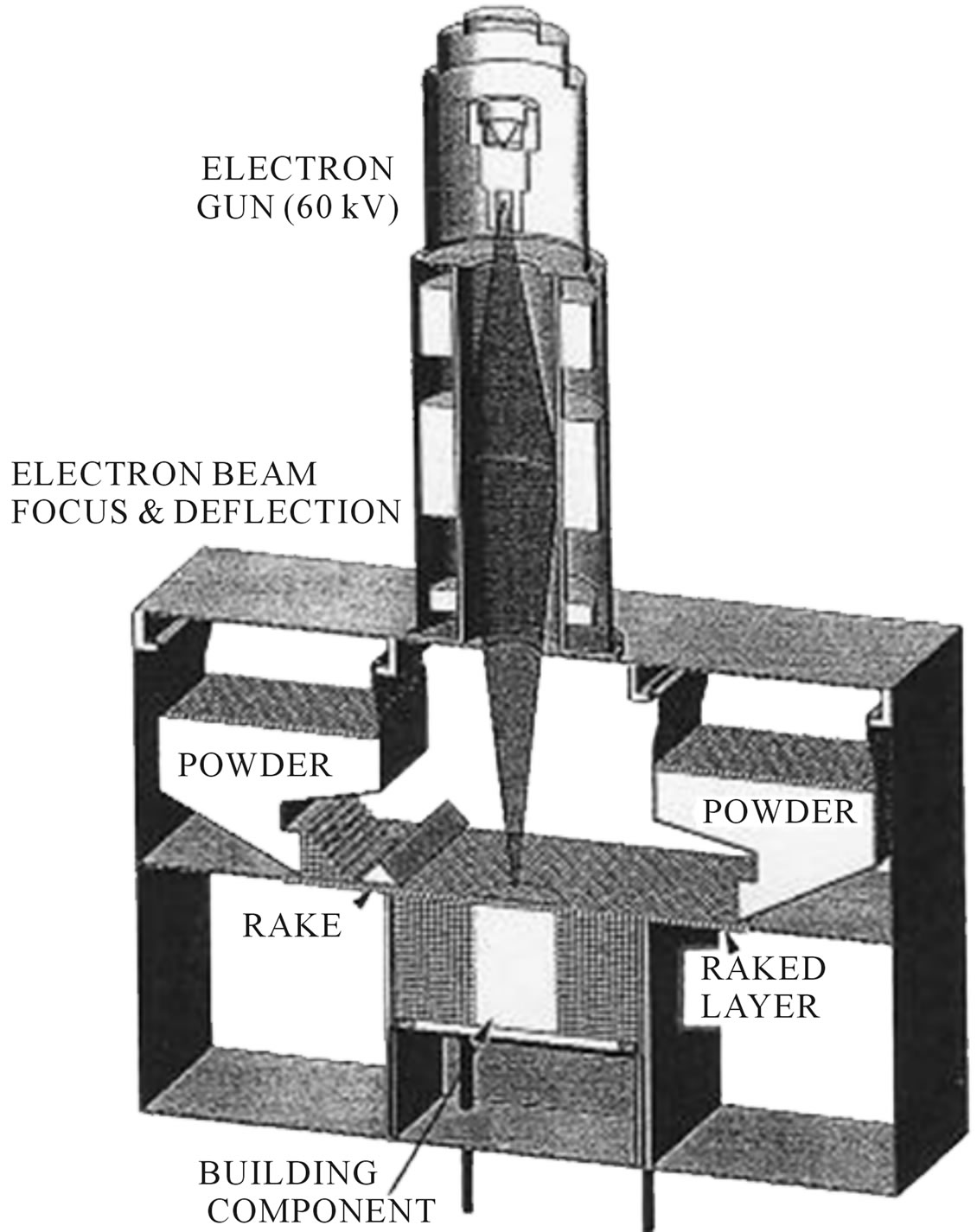
Figure 1. Arcam A2 EBM system schematic.
used to fabricate Ti-6Al-4V test cylinders measuring 2 cm in diameter and 8 cm in length. These cylinders were built in both a vertical orientation (with the cylinder axis parallel to the z-axis build direction) and a horizontal (with the cylinder axis perpendicular to the build direction or in the x-y powder layer plane) orientation. Figure 2 shows the build model for these test specimen orientations. The Ti-6Al-4V powder (nominally 6.2% Al, 3.6% V, 0.13% O; average powder diameter of 30 µm) was gravity fed from cassettes shown in Figure 1 onto the build table where it was raked into a layer roughly 3 particle diameters thick. This raked layer was preheated (to ~650˚C) by scanning the electron beam at speeds of ~104 mm/s in multiple scans (~11) at ~30 mA beam current, using an accelerating voltage of 60 kV. The system vacuum was >10−4 Torr, while a He gas bleed in the build area reduced the vacuum but improved build component cooling. During the melt scan following the preheat scanning, the beam current was reduced to 6 mA. Melt scan rates in this study included 100, 400, 500, 600, 700, and 1000 mm·s−1. The beam focus and scan spacing were maintained at a constant value during the cylindrical specimen fabrication illustrated in Figure 2.
Disc sections were cut from the vertical (z-axis) built cylinders perpendicular to the build direction along the cylinder axis while rectangular sections were cut parallel to the horizontal cylinder axes, and perpendicular to the build direction. These sections were ground, polished,
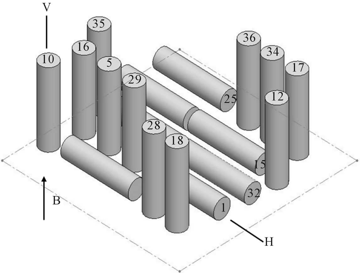
Figure 2. Isometric CAD model representing vertical (V) and horizontal (H) build orientations. The build direction is represented by arrow denoted B.
and etched with a Kroll reagent consisting of 0.1 L water, 5 mL nitric acid and 2.5 mL hydrofluoric acid for about 3 s. Thin slices were also prepared from these specimen sections and ground to 0.2 mm thicknesses from which 3 mm discs were punched in order to prepare TEM specimens using a dual-jet electropolishing system and an electrolyte consisting of 0.9 L methanol to which 50 mL sulfuric acid was added. Electropolishing was performed at −10˚C at 15 - 25 volts.
For LOM observations, we employed a Reichert MEF4 A/M metallograph with a digital imaging system. Samples prepared for LOM by etching were also observed directly in the SEM (A Hitachi S-4800 field-emission SEM) operated at 20 kV in the secondary electron emission mode. The SEM was also fitted with an energydispersive (X-ray) spectrometer system for elemental analysis. Specimens for TEM were observed in a highresolution, Hitachi H-9500 TEM operated at 300 kV, employing a goniometer-tilt stage.
The specimen sections cut from the vertical and horizontal-built cylindrical components illustrated in Figure 2 for LOM were also used for macro and micro-hardness testing. Rockwell-C-scale macrohardness was measured using a 1.5 kN load, while digital Vickers microindentation hardness was measured using a 100 gf (0.1 N) load. Macrohardness (HRC) was averaged from a minimum of 10 indentations per sample, while microhardness (HV) in units of GPa was averaged from a minimum of 10 indentations, representing 20 diagonals.
Representative horizontal and vertical cylinders built in arrays as shown in Figure 2 were also machined into standard tensile specimens for tensile testing at room temperature (20˚C) using a strain rate of 2 × 10⁻³·s−1. These tests were averaged from 3 specimens in both the vertical and horizontal build orientations (Figure 2) for each build corresponding to the melt scan rates noted earlier. This was true for macro and micro-indentation hardness testing as well.
For samples prepared at each melt-scan as modeled in Figure 2, the density was measured and compared with ideal, fully dense Ti-6Al-4V (having a density rs of 4.42 g/cm3) as relative density: r/rs. The corresponding porosity (in percent) was then obtained from (1 – r/rs) 100.
3. Results and Discussion
Table 1 provides a summary matrix for this experimental study and illustrates generally that as the melt scan rate increased for the EBM fabrication of vertically or horizontally built cylinders, the Young’s modulus (or stiffness) decreased along with the tensile properties and macrohardness (HRC), corresponding to an increase in residual porosity. The notable variance in Table 1 was the increase in microhardness (HV) with increasing porosity for the horizontal built cylinders compared to the vertical built cylinders were the values increased then decreased. This contrast in macrohardness and microhardness is due to the response of the Rockwell indenter to porosity, while the Vickers indenter responded almost exclusively to microstructural variations which occurred in response to the melt scan rate change. It can be recalled that the Rockwell indenter represents a load of 1.5 kN while the Vickers indenter represents a load of only 0.1 N. Consequently, the macrostructure is being influenced by increasing porosity and correspondingly by microstructural changes in acicular α grain size and related phenomena.
Figure 3 illustrates the porosity variations which occurred at melt scan rates of 100 and 1000 mm·s−1 in both the vertically built and horizontally built cylinders. These porous regions are characterized by unmelted or unsintered powder particle zones which increase in size and frequency with melt scan rate. In addition, the porosity tended to be somewhat more prevalent in the cylinders built horizontally (in the x-y powder bed plane in Figure 1) because of the more rapid cooling occurring for these geometries in contrast to the vertical cylinders where heat flow and high thermal gradients reduced the cooling rate. The porous regions illustrated in Figure 3 were also observed by Gaytan et al. [6] for systematic variations in the beam current in the EBM fabrication of Ti-6Al-4V components with much higher porosities.
It is interesting to observe, as illustrated in Figure 4, that the relative stiffness (E/Es) in Table 1 can be related to the relative density (r/rs) in a log-log plot similar to the ideal relationship for foams as established by Gibson and Ashby [7]: (E/Es) = (r/rs)2. Even though the porous components fabricated in this study do not resemble regular open-cellular structures, the stiffness is corre-
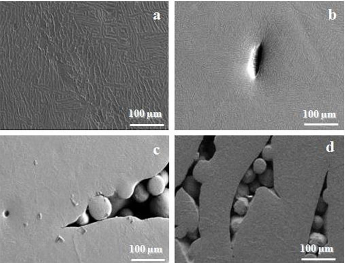
Figure 3. SEM views of porosity in vertical (V) and horizontal (H) oriented cylindrical components at melt scans noted. (a) V-100 mm·s−1; (b) H-100 mm·s−1; (c) V-1000 mm·s−1; (d) H-1000 mm·s−1.
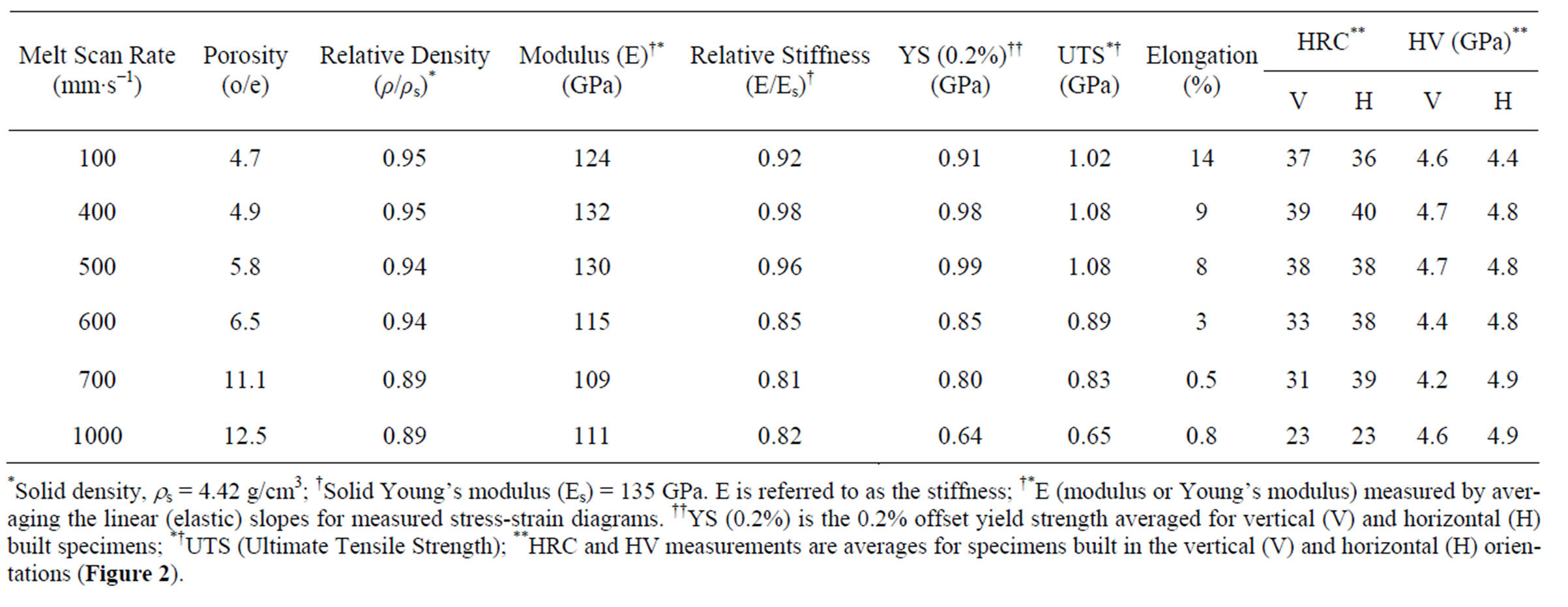
Table 1. Properties for Ti-6Al-4V cylindrical components.
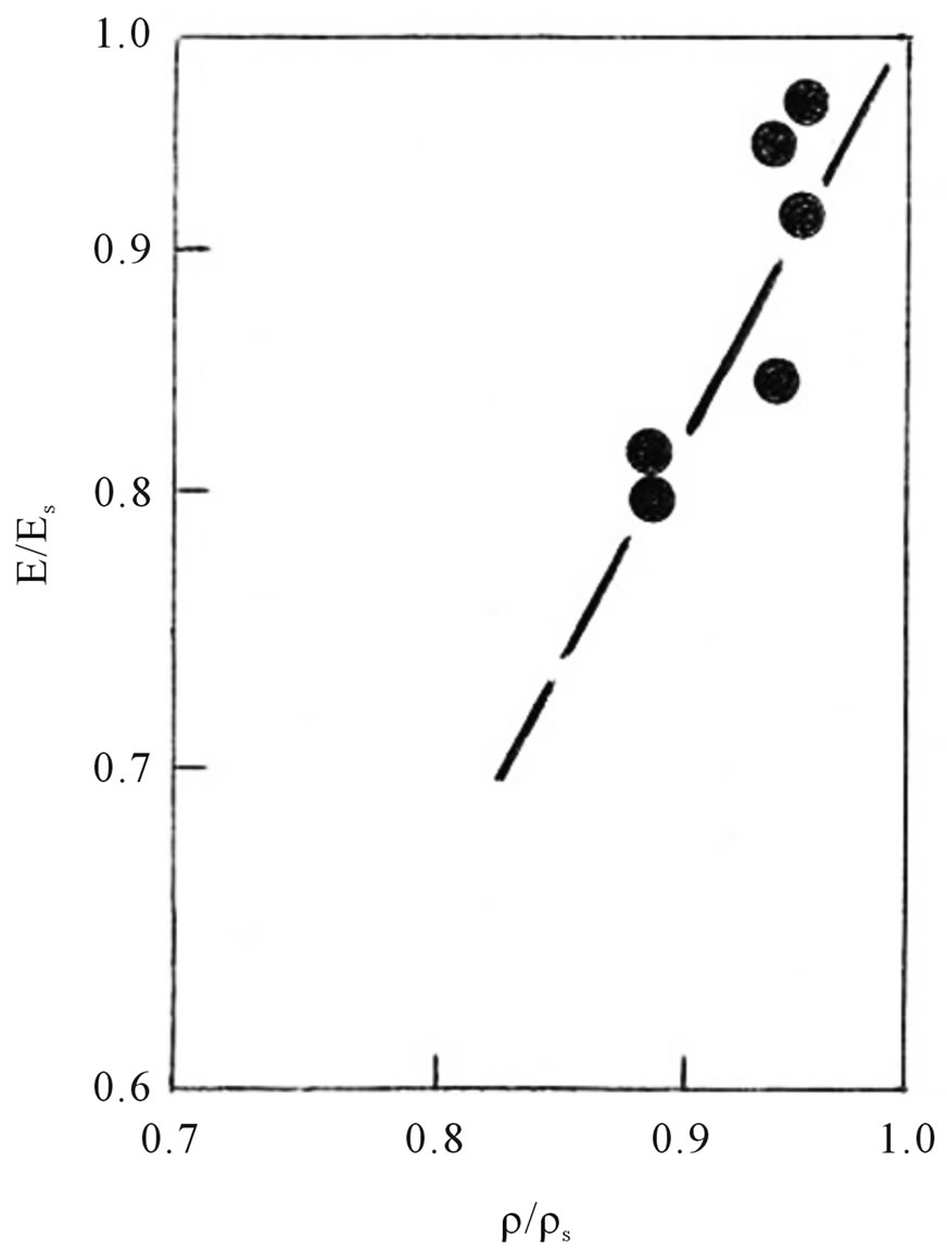
Figure 4. Log—log plot for relative stiffness (E/Es) versus relative density (ρ/ρs) for EBM-fabricated Ti-6Al-4V, averaged for vertical and horizontal build orientations represented in Figure 2.
spondingly represented in that form for the narrow range of modulus (E) measured. Murr et al. [8,9] have recently demonstrated that regular mesh and foam samples fabricated from Ti-6Al-4V by EBM generally follow this ideal relationship.
Figure 5 illustrates the microstructure changes which occur at 1000 mm·s−1 melt scan rate in contrast to the slower starting rate of 100 mm·s−1, in the vertical and horizontal builds corresponding to Figure 3. It can be observed that the acicular α phase width or plate thickness (t in Figure 5(a)) is smaller for the more rapidly cooling horizontal (H) builds in contrast to the vertical (V) builds, and that the acicular α-phase becomes mixed with the martensitic α¢-phase at 1000 mm·s−1 (Figures 5(c) and (d)). The α¢-phase, shown dark in Figure 5(d) is a more uniform plate with decreasing thickness in contrast to the acicular α-phase plates in Figure 5(a). Figure 6 shows TEM images for the α-phase microstructure in Figure 5(a) and the α¢-martensite in Figure 5(d). The dark, interphase region in Figures 5(a) and (b) represent the bcc b-phase (a = 0.33 nm), also shown in Figure 6(a).
Figure 7 summarizes measurements of α and α¢-phase plate thicknesses with EBM melt scan rate for cylindrical samples built in vertical (V) and horizontal (H) orientations represented in Figure 2. These dimensional, microstructure reductions correspond to the more rapid melt scan rates providing more rapid solidification, and promoting α¢-martensite formation [4-6]. These decreasing microstructure widths also correlate roughly with in-
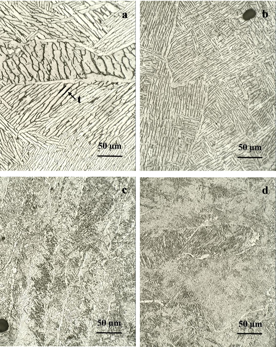
Figure 5. LOM images for acicular a-phase and α¢-martensite plates in vertical (V) and horizontal (H) cylindrical component orientations, at melt scan rates noted. (a) V-100 mm·s−1; (b) H-100 mm·s−1; (c) V-1000 mm·s−1; (d) H-1000 mm·s−1.
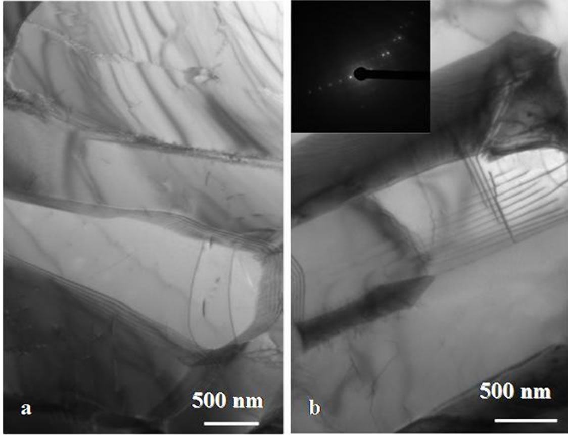
Figure 6. TEM images showing a, b, and a¢-phase features. (a) Horizontal build, 100 mm·s−1. (b) Horizontal build, 1000 mm·s−1.
creasing Vickers (HV) microindentation hardness increases illustrated in Table 1. It is also observed that there is a thermal gradient between the component top and bottom regions: hotter at the top, especially for the vertical builds. This promotes α-phase grain growth and acicular plate width increases, particularly notable on
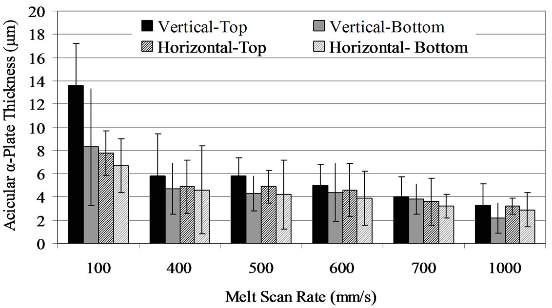
Figure 7. Acicular α and α¢ plate thickness variation for vertical (V) and horizontal (H) build components versus melt scan rate.
comparing the top and bottom cylindrical components built in the vertical (V) orientation. Similar observations in microstructures were also observed in previous work of Thijs et al. [4] for laser beam fabrication as well as Gaytan et al. [6] for electron beam (EBM) fabrication of Ti-6Al-4V.
It can be noted in Table 1, and with reference to the microstructural observations in Figures 5 and 6, and including the microstructure size variations noted in Figure 7, that there is a macrohardness-microhardness dicotomy where rapid solidification promotes microstructure refinement while simultaneously promoting increased porosity.
4. Conclusion
Increasing the melt scan rate from 100 to 1000 mm·s−1 in the EBM fabrication of oriented Ti-6Al-4V cylinders increases the cooling (solidification) rate and this results in a decreasing α-phase acicular grain width as well as an increasing proportion of α'-martensite plate production. This decreasing microstructure dimension (or refinement) increases the microindentation hardness (HV) for the horizontal built cylinders. Correspondingly, increasing melt scan rate increases the porosity by creating unsintered powder volumes within the layers. This porosity increase corresponds to a decreasing macrohardness (HRC) and a proportionate decrease in relative stiffness with relative density. The HRC measurements are sensitive to the porous macrostructure while the HV measurements are related to the microstructure. The geometry or orientation of fabricated cylindrical components influences the local heat transfer conditions which influence the microstructure, especially the volume fraction of α'-martensite. In effect, the cylindrical components oriented in the powder bed plane cooled more rapidly than those in the build direction perpendicular to the build plane, resulting in slight microindentation hardness increase. Microstructures near the top of vertically built cylinders were also slightly coarser than those near the bottom because of thermal gradients.
5. Acknowledgements
We are grateful for support from the Louis Stokes Alliance for Minority Participation (LSAMP) Bridge to Doctorate Fellowship Grant HRD-0832951, and Mr. and Mrs. MacIntosh Murchison Endowments at the University of Texas at El Paso.
REFERENCES
- S. M. Gaytan, L. E. Murr, D. A. Ramirez, B. I. Machado, E. Martinez, D. H. Hernandez, J. L. Martinez, F. Medina and R. B. Wicker, “A TEM Study of Cobalt-Base Alloy Prototypes Fabricated by EBM,” Materials Science and Applications, Vol. 2, No. 5, 2011, pp. 355-363. doi:10.4236/msa.2011.25046
- L. E. Murr, E. Martinez, S. M. Gaytan and D. A. Ramirez, “Contributions of Light Optical Microscopy to Contemporary Materials Characterization: The New Directional Solidification,” Metallography, Microstructure and Analysis, Vol. 1, No. 1, 2012. doi:10.1007/s13632-011-0002-8
- L. E. Murr, S. M. Gaytan, D. A. Ramirez, E. Martinez, J. Hernandez, K. N. Amato, P. W. Shindo, F. R. Medina and R. B. Wicker, “Metal Fabrication by Additive Manufacturing Using Laser and Electron Beam Melting Technologies,” Journal of Materials Science and Technology, Vol. 28, No. 1, 2012, pp. 1-14. doi:10.1016/S1005-0302(12)60016-4
- L. Thijs, F. Verhaeghe, T. Craeghs, J. Van Humbeeck, and J.-P. Kruth, “A Study of the Microstructural Evolution During Selective Laser Melting of Ti-6Al-4V,” Acta Materialia, Vol. 58, No. 9, 2010, pp. 3303-3312. doi:10.1016/j.actamat.2010.02.004
- L. E. Murr, S. A. Quinones, S. M. Gaytan, M. I. Lopez, A. Rodela, E. Y. Martinez, D. H. Hernandez, E. Martinez, F. Medina and R. B. Wicker, “Microstructure and Mechanical Behavior of Ti-6Al-4V for Biomedical Applications Produced by Rapid-Layer Manufacturing,” Journal of Mechanical Behavior of Biomedical Materials, Vol. 2, No. 1, 2009, pp. 20-32. doi:10.1016/j.jmbbm.2008.05.004
- S. M. Gaytan, L. E. Murr, F. Medina, E. Martinez, M. I. Lopez and R. B. Wicker, “Advanced Metal Powder-Based Manufacturing of Complex Components by Electron Beam Melting,” Materials Technology: Advanced Performance Materials, Vol. 24, No. 3, 2009, pp. 180-190.
- L. J. Gibson and M. F. Ashby, “The Mechanics of ThreeDimensional Cellular Materials,” Proceedings of the Royal Society, Vol. 382, No. 1782, 1982, pp. 43-59. doi:10.1098/rspa.1982.0088
- L. E. Murr, S. M. Gaytan, F. Medina, H. Lopez, E. Martinez, B. I. Machado, D. H. Hernandez, L. Martinez, M. I. Lopez, L. B. Wicker and J. Bracke, “Next Generation Biomedical Implants Using Additive Manufacturing of Complex Cellular and Functional Mesh Arrays,” Philosophical Transactions of the Royal Society A, Vol. 368, No. 1917, 2010, pp. 1999-2032. doi:10.1098/rsta.2010.0010
- L. E. Murr, K. N. Amato, S. J. Li, Y.-X. Tian, X.-Y. Cheng, S. M. Gaytan, E. Martinez, P. W. Shindo, F. Medina and R. B. Wicker, “Microstructure and Mechanical Properties of Open-Cellular Biomaterials Prototypes for Total Knee Replacement Implants Fabricated by Electron Beam Melting,” Journal of Mechanical Behavior of Biomedical Materials, Vol. 4, No. 7, 2011, pp. 1396-1411. doi:10.1016/j.jmbbm.2011.05.010