Materials Sciences and Applications
Vol.3 No.9(2012), Article ID:22858,9 pages DOI:10.4236/msa.2012.39084
Effect of Radial Expansion of Cr-Mo Steel Tubes on Their Corrosion Behavior in Sea Water
![]()
1Mechanical Engineering Department, Petroleum Institute, Abu Dhabi, UAE; 2Chemistry Department, Petroleum Institute, Abu Dhabi, UAE; 3Metallurgical & Materials Engineering Department, Colorado School of Mines, Golden, USA.
Email: *aseibi@pi.ac.ae
Received March 22nd, 2012; revised May 7th, 2012; accepted June 19th, 2012
Keywords: Expanded Tubes; Corrosion in Seawater; Potentiostat; Hardness; Enlarged Grain Size
ABSTRACT
This paper studies the effect of expansion ratio on the corrosion rate of the expanded tubes exposed to sea water as well as the microstructure changes caused by the expansion of Cr-Mo steel tubes to large permanent deformations. 2.25 Cr-1.0 Mo steel (schedule 40 and schedule 80) tubes were subjected to various expansion ratios of 10%, 15%, 20%, and 25% by pushing conical mandrels through them using a piston. The microstructure was also studied to determine the effect of the expansion on the grain structure of the material. Microscopic examination of the expanded tubes revealed that grains elongate along the direction of the hoop stress and this elongation increases with an increase of expansion ratio. Moreover, it was found that corrosion rate and hardness increase with an increase in expansion ratio.
1. Introduction
Downhole tubular expansion of pipes (casings) is becoming a normal practice in the petroleum industry to repair damaged casings, shutdown perforations, and ultimately achieve mono-diameter wells. Tubular expansion is a cold drawing metal forming process, which consists of running conical mandrels through casings either mechanically using a piston or hydraulically by applying a back pressure. This mechanism subjects the pipes to large radial plastic deformations up to 30% of the inner diameter. Extensive literature related to the viability and advantages of this technology in the field is summarized [1]. Experimental and numerical studies were carried out in the past two decades to understand the mechanical behavior of expanded tubes/pipes. However, a limited number of research work related to the corrosion behavior of plastically deformed materials is available in the literature. The effect of the degree of corrosion on the mechanical properties of steel under plastic deformation was reported to be critical [2]. The study revealed that the hardness of 8 mm bars BSt500s steel reduced by 25% - 35% and 2% - 10% in the outer and inner layers, which is due to removal of the martensite layer in the outer layer [3]. Moreover, it was found that the increase in the degree of plastic deformation aids the anodic and cathodic reactions between a steel boiler and the acid solution that was used for flushing [4]. The present paper, therefore, studies the effect of expansion ratio on the corrosion rate of 2.25 Cr-1.0 Mo steel samples exposed to aerated sea water as well as the hardness and microstructure changes of expanded tubes.
2. Theoretical Background
2.1. Stress Analysis
The mechanical response of tubes subjected to radial expansion was studied [5] by considering the equilibrium conditions of an infinitesimal element (see Figure 1) from which an expression for the hoop stress was deduced:
 (1)
(1)
where qm represents the contact pressure between the mandrel and tube surface and is given by
 (2)
(2)
The terms Fc, pm, µ denote respectively the expansion force, contact pressure, and friction coefficient. Equation (1) expresses the stress in terms of the contact pressure,
 (a) (b) (c)
Figure 1. Tubular expansion under compression. (a) Infinitesimal tubular element; (b) Mandrel under expansion; (c) Mandrel FBD. (The reference coordinates (x, y) are moving with a constant velocity vt along x-axis).
qm, mandrel angle, α, initial pipe thickness, t1, and the initial and post expansion tubular radii r1 and r2, respectively. The parameters h1, h2, and h3 are defined by:
 (3)
(3)
2.2. Corrosion Rate Calculation
Corrosion rate measurements are generally performed by 1) Calculating the mass loss per unit surface area of the corroding specimen and 2) Using potentiostatic measurements [6,7]. Two main techniques are available, Tafel extrapolation and Linear Polarization Resistance, RP. The Polarization Resistance Method is adopted in this research. This resistance is inversely proportional to the corrosion current, icorr.
 (4)
(4)
Where βa and βc are the anodic and cathodic Tafel constants. Typically, a β value of 100 mV is chosen. The corrosion current density, i (A·cm–2) can be related to the corrosion penetration rate in mils per year (mpy) by Faraday’s law:
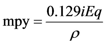 (5)
(5)
where Eq and r denote equivalent weight, and density, respectively.
2.3. Grain Size Determination
The average linear intercept diameter method is used to characterize the grain sizes [8]. The calculations were performed based on 100× magnification. The average intercept diameter, d, and the ASTM grain size number, N, are given by:
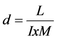 (6)
(6)
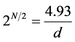 (7)
(7)
where L is the total length, I is the number of intercepts and M is the magnification.
Equation (7) expresses the grain size number, N, in terms of the average intercept diameter, d, where large values of N indicate a fine grain size or more number of grains per square area. With an increase of the grain diameter, d, by a factor of , the value of n is cut in half and N is decreased by 18.
3. Experimental Study
The experimental study consisted of three major tests: 1) Tubular expansion; 2) Corrosion; and 3) Hardness test and metallurgical examination of expanded tubes. The first test consists of expanding steel tubes to various expansion ratios by drawing conical mandrels through them using a mechanical press machine while the second and third tests studied respectively the corrosion rate and surface examination/hardness tests of expanded steel tubes.
3.1. Tubular Expansion and Testing Procedure
2.25 Cr-1.0 Mo steel (schedule 40 and schedule 80) tubes of 300 mm length were tested under the conditions described in Table 1. The conical mandrels were designed and manufactured according to the specifications listed in Table 1 in order to obtain the desired expansion ratio. Tube expansion was performed using a mechanical press machine (see Figure 2). All tubes were lubricated prior to expansion in order to minimize friction and hence wearing of the inner tube surface and the mandrel. Expansion was performed by applying a hydraulic pressure to drive the rod/mandrel system through the tubes. The hydraulic pressure, Pm, was recorded directly from the pressure gauge which is attached to the pressing machine. The measured pressure was used to estimate the induced hoop stress at various expansion ratios and cone angles using Equation (1).
3.2. Corrosion Testing
Representative specimens of 2.5 × 2.5 cm were cut from the expanded part of the tubes. A 10 cm length of insulated copper wire (8 swg) was soldered to the corner of
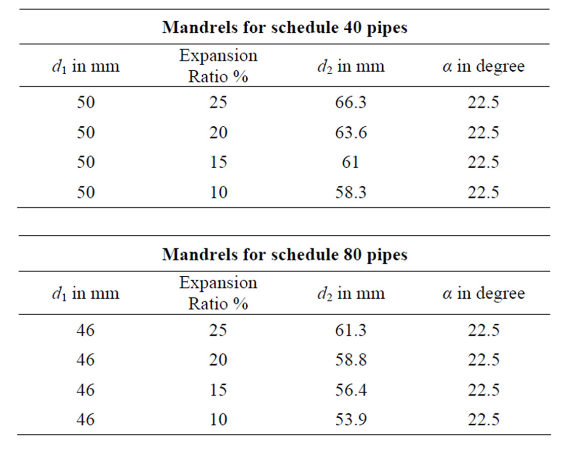
Table 1. Mandrel dimensions used for tube expansion.
each coupon. The specimen surface which corresponds to the tube outer surface was cleaned and smoothened with sandpaper while the rest of the faces (the soldered joint and bare copper) were coated with nail polish to protect them from contact with the corrosive fluid. This was followed by washing the samples with 0.1 HCl, ethanol, and finally rinsed with distilled water. The corrosion test cell was filled with sea water (see Figure 3) and samples were placed one by one for testing using a Parr 273 potentiostat, set to record the Linear Polarization Resistance. The sea water inside the test cell was changed after every three measurements to avoid the debris of the corrosion products and any misreading taken in later measurements. The seawater was constantly aerated with atmospheric air.
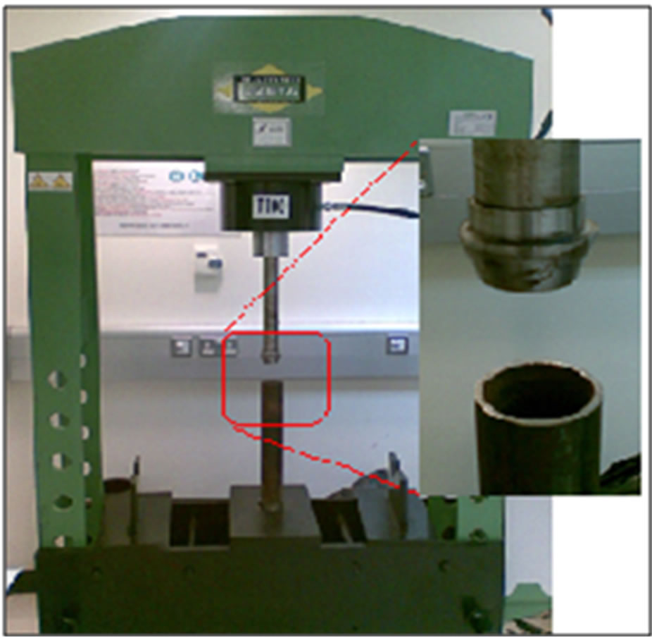
Figure 2. Press machine used for expansion.
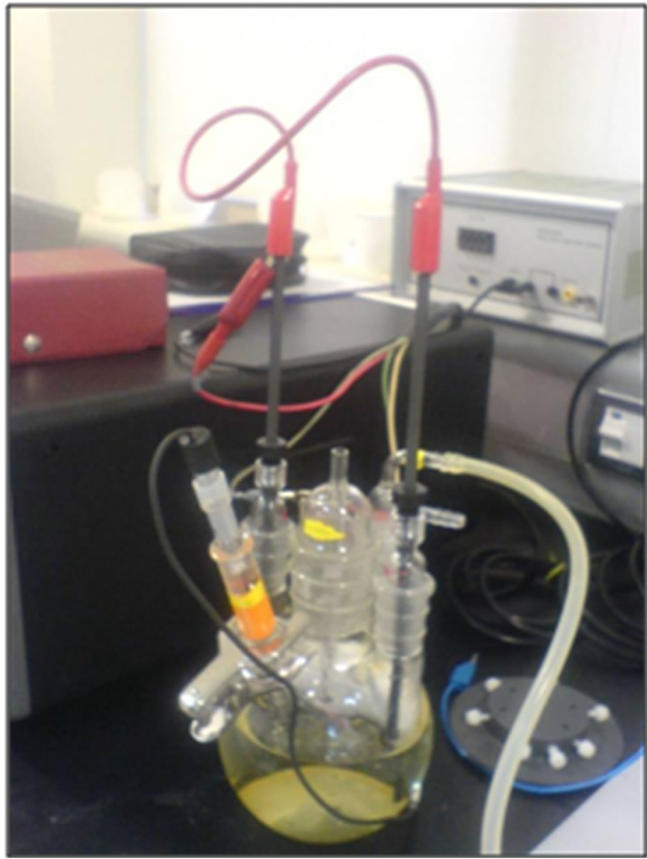
Figure 3. Corrosion rate setup.
3.3. Hardness Testing and Microscopic Examination
Expansion of tubes to large radial plastic deformation plays a major role in altering the mechanical properties and microstructure of the tested samples. Thereby, the aim of these tests is determine to what extent the expansion process affects the hardness and microstructure of the expanded tubes. Samples of 0.5 × 1.5 cm were cut from the schedule 40 expanded tubes using a rotating disc cutting machine. The coupons were then embedded in an epoxy resin mold using a press mount machine where the outer tube surface was exposed for hardness measurements and microscopic examination. The samples were then grinded and polished to a mirror like finish. Both Vickers and Rockwell C hardness were measured using a universal hardness tester. After conducting the hardness measurements, the samples were etched using 5% nitric acid in ethanol for surface examination using the optical and scanning electron microscopes.
4. Results and Discussion
The testing program involved three major tests: 1) Expansion of steel tubes; 2) Corrosion rate; and 3) Hardness and microscopic examinations. Cr-Mo steel pipes of two different thickness (schedule 40 and schedule 80) were expanded to expansion ratios of 10%, 15%, 20%, and 25% and the corresponding required pressures were measured from which the induced hoop stress was estimated using Equation (1). Both Figures 4 and 5 show the variation of hoop stress for both pipe types in terms of expansion ratio and friction coefficient. It can be seen that the hoop stress increases by a factor of three when expanded at 10% and 25% indicating that the expansion ratio has a great effect on the induced stresses. Moreover, the figures show that the hoop stress increases as the friction coefficient decreases indicating more energy is allocated to expanding the tubes. In other words, part of the total energy provided by the system to expand the tubes is dissipated by friction; thereby, the less energy loss the more expansion is achieved. It was
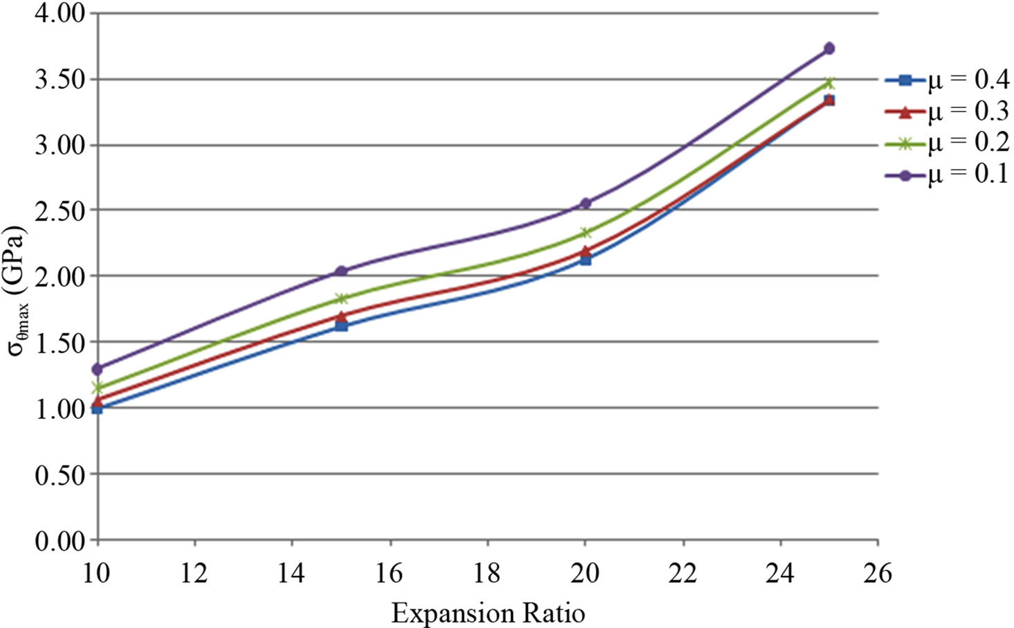
Figure 4. Maximum hoop stress vs. expansion ratio for different friction coefficients at fixed cone angle for steel schedule 40.
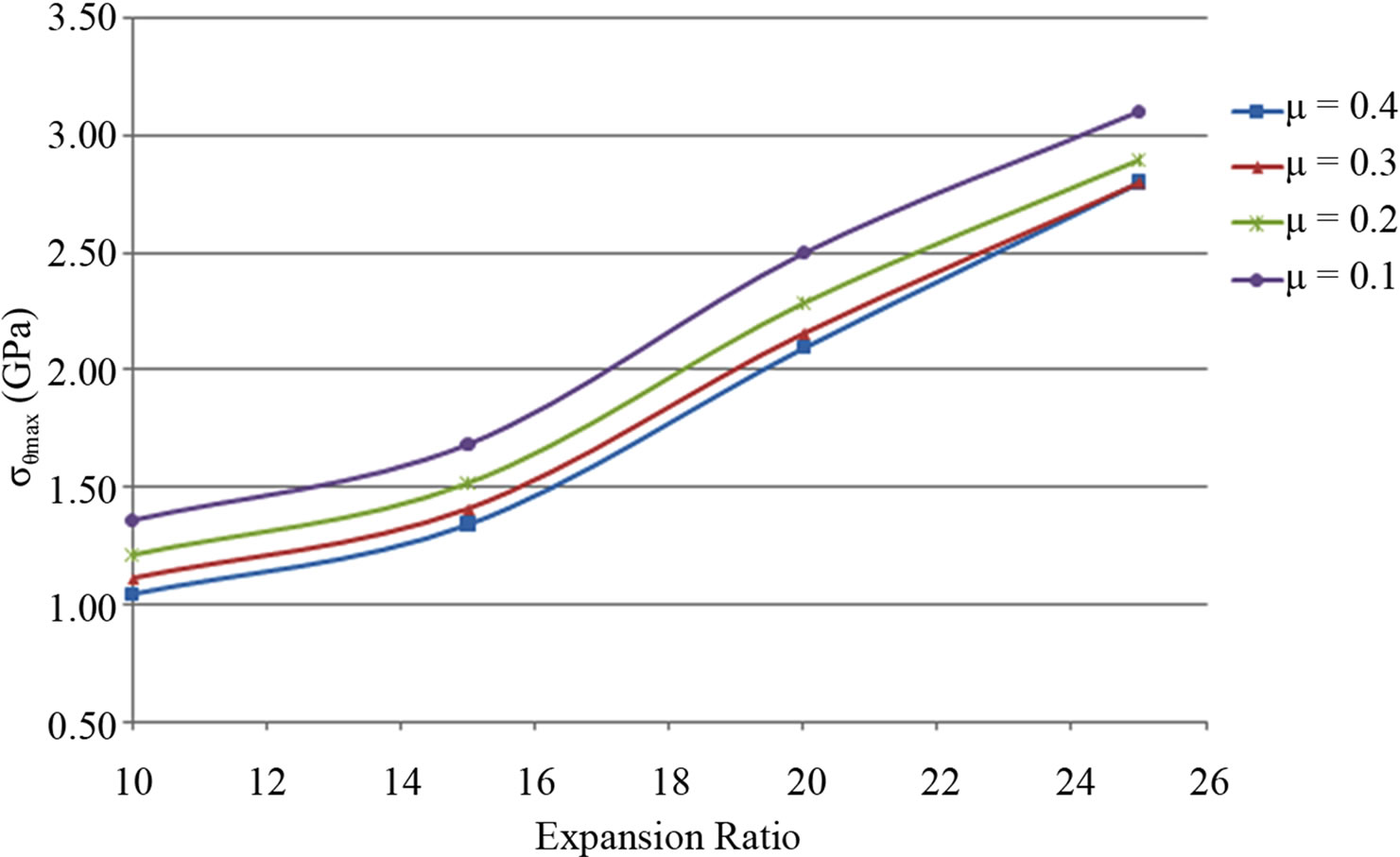
Figure 5. Maximum hoop stress vs. expansion ratio for different friction coefficients at fixed cone angle for steel schedule 80.
also observed that the force required for expanding schedule 80 is greater than that for schedule 40 tubes. This is due to the increase in tube wall thickness for schedule 80. It is worth noting that expansion of tubes at 25% resulted in the development of a sudden crack immediately after approximately five seconds from launching the experiment (Figure 6).
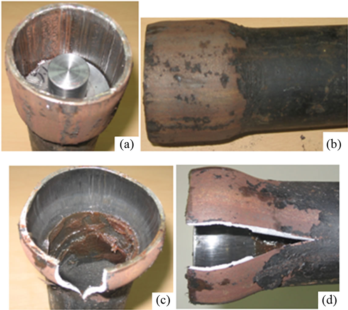
Figure 6. Expanded S40 pipes (a) and (b) uniform expansion at 15% expansion while (c) and (d) pipes cracked open at 25% expansion.
4.1. Corrosion Measurements
Expansion of the steel tubes increases the corrosion current flowing through the pipe sample in the electrochemical cell used in the experiment. This is due to the decrease in the samples’ polarization resistance (Rp) which is measured by calculating the tangent slope at Ecorr (at value of over-voltage = 0 mV in the vertical axis because ε = Eapp – Ecorr). A typical linear polarization curve for a steel sample of schedule 40 expanded to 25% is presented in Figure 7.
The fluctuations in the readings of the potentiostat observed in Figure 7 are due to the sensitivity of the potentiostat to the vibration of the sample due to swirling of the water and air bubbles caused by the stirrer as well as the bubbler which may also cause some errors in the readings. Therefore, as a precaution the samples were fixed to the cap to reduce its vibration.
Results of the tested samples at various expansion ratios indicate that the increase in expansion ratio results in an increase in the corrosion current for both pipe types as shown in Figure 8.
The corrosion current (Icorr) was calculated by the software used in monitoring the potentiostat output depending on the Rp values approximated from the Linear Polarization Curves. A typical example illustrating estimation of the corrosion rate for the measurement of corrosion current density of Icorr = 0.112095 mA/cm2 at 20% expansion
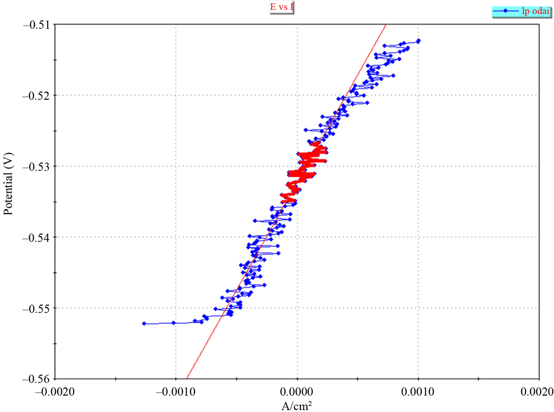
Figure 7. Linear polarization curve with Rp fit applied for schedule 40 pipe of 25% expansion.
ratio of schedule 40 is shown below:
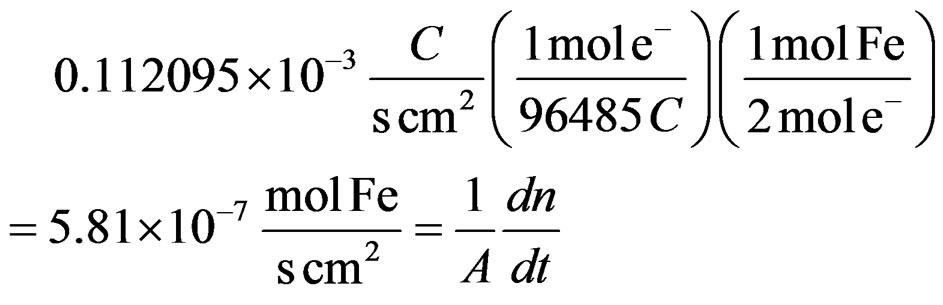
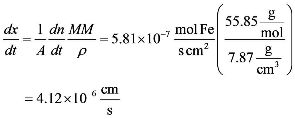
This leads to a corrosion rate of:
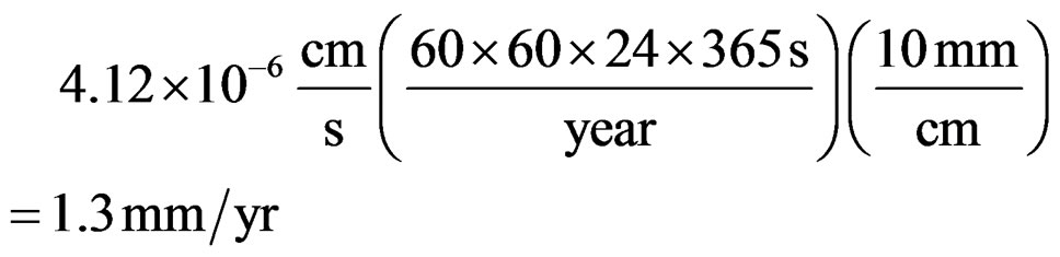
Figure 9 shows the resulting corrosion rates for the two types of steel at various expansion ratios. It can be seen that the corrosion rate is higher for schedule 80 and increases as the expansion increases for both steel materials indicating that tubes expanded at higher expansion ratios are more susceptible to corrosion. This may be due to several factors such as the increase in micro cracks and imperfections in the metal lattice and surface caused by the tension applied while expanding beyond the elastic region. This creates weak points that act like an anode or cathode parts of the electrochemical reaction causing corrosion on the surface of the metal. In addition, the expansion process increases the inter-granular interfaces and stretches the metal grains which also increase the surface area of the carbides.
4.2. Hardness Measurements and Microscopic Examination
The hardness and microstructure of expanded tubes were performed to assess the level of deterioration of the mechanical properties and change in granular size and rearrangements. Table 2 summarizes the results of the measured hardness values for schedule 40 using Vickers and Rockwell hardness C tests. It can be seen that there is a slight increase in the hardness as the expansion ratio increases. This increase is due to dislocation movements within the crystal structure of the steel due to plastic deformation. This deformation increases the concentration of dislocations which may subsequently form low-angle grain boundaries surrounding sub-grains. This also indicates that the expansion ratio results in higher yield strengths and decrease in ductility.
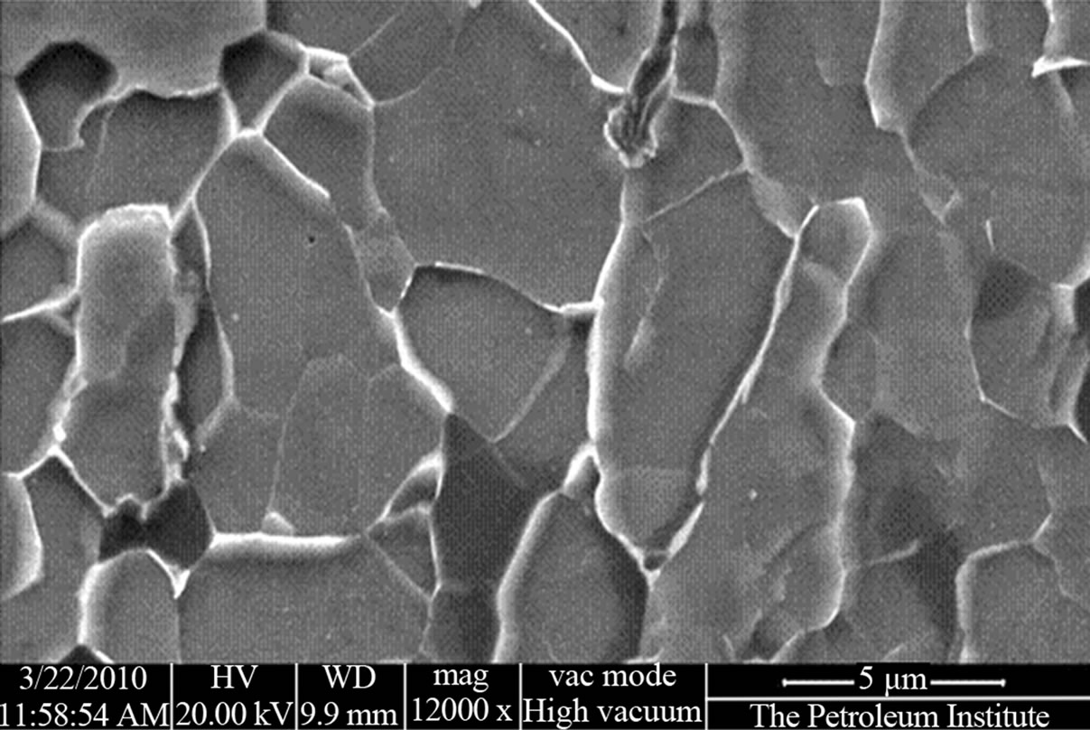
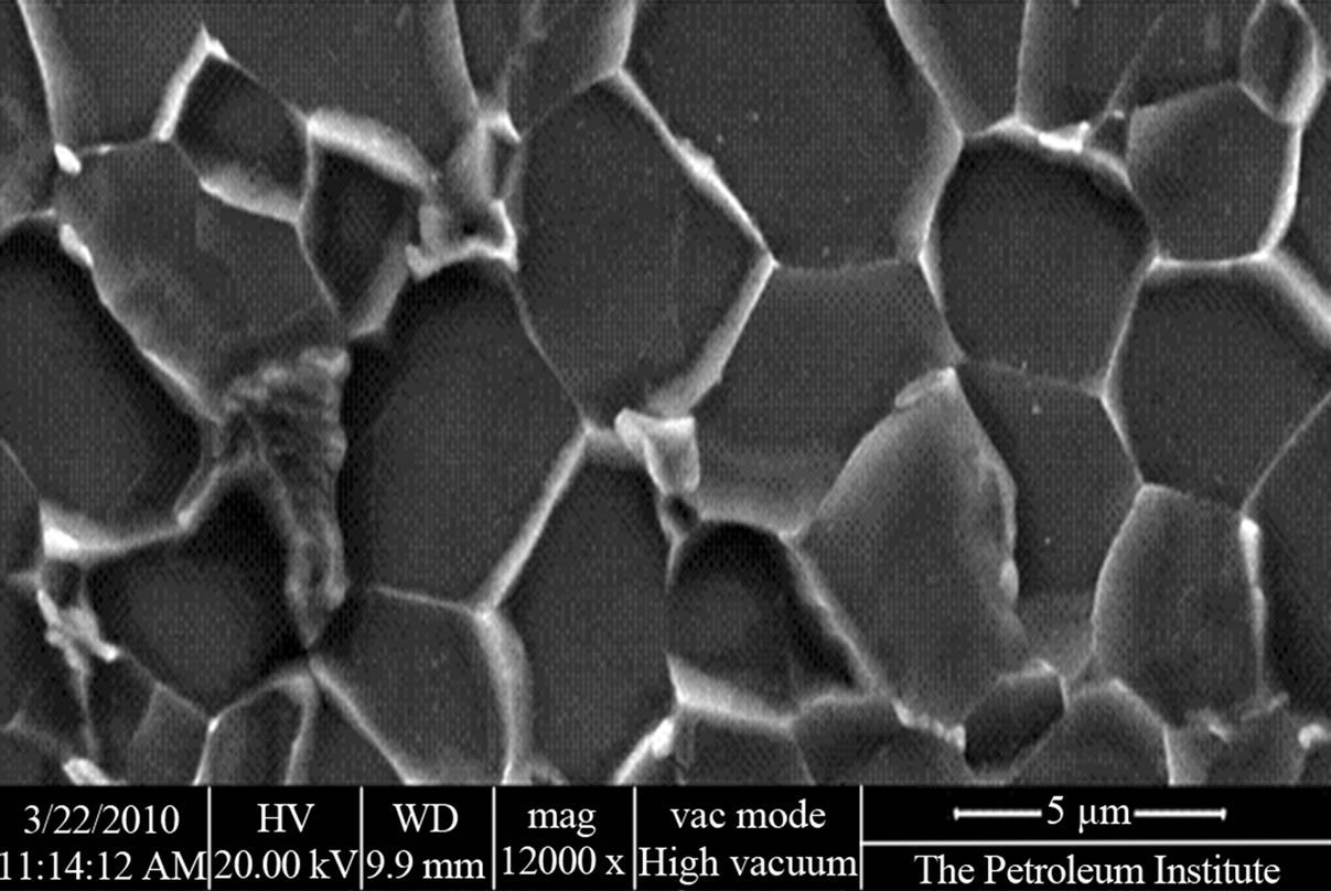
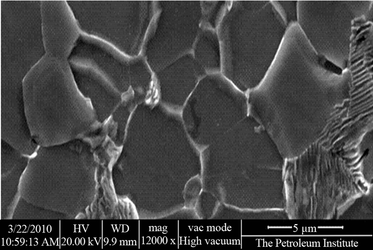
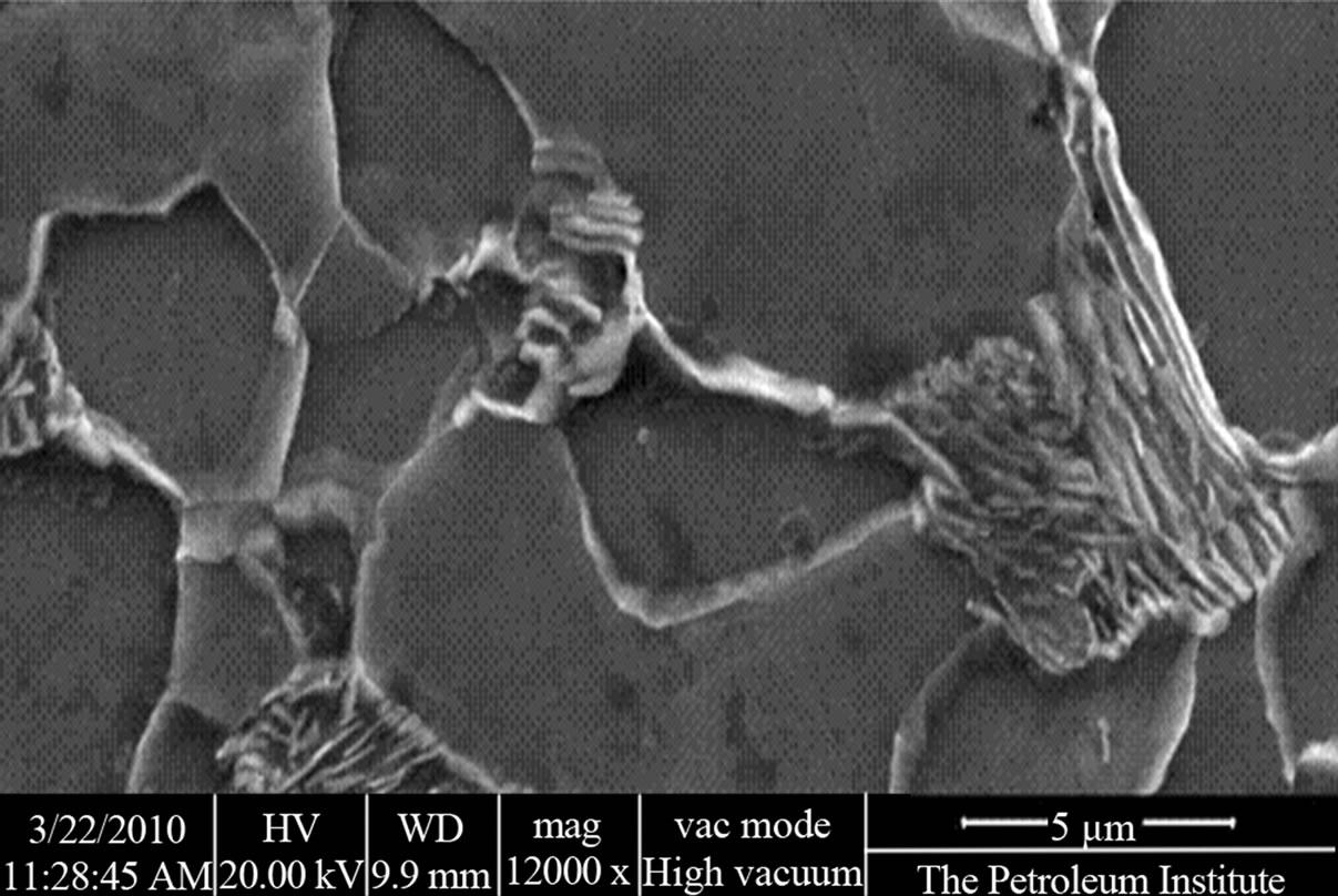
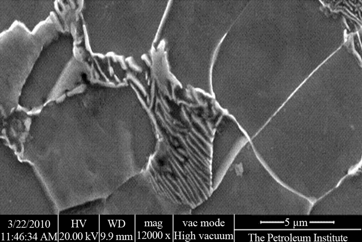
The hardness of the steel was found to be very important when determining the susceptibility of the material to stress corrosion cracking (SCC). NACE standard MR0175 states that steel has to have a hardness level > 22 Rockwell C for SCC to occur [9]. Typical microstructures of the schedule 40 coupons illustrate an obvious increase in the grain size as the plastic deformation increases by expanding the tubes (see Figures 10-14). It is also clear from the microscopic observations that the area of the ferrite “the light grains” increases significantly by expansion.
The hardness of the steel was found to be very important when determining the susceptibility of the material to stress corrosion cracking (SCC). NACE standard MR0175 states that steel has to have a hardness level > 22 Rockwell C for SCC to occur [9]. Typical microstructures of the schedule 40 coupons illustrate an obvious increase in the grain size as the plastic deformation increases by expanding the tubes (see Figures 10-14). It is also clear from the microscopic observations that the area of the ferrite “the light grains” increases significantly by expansion.
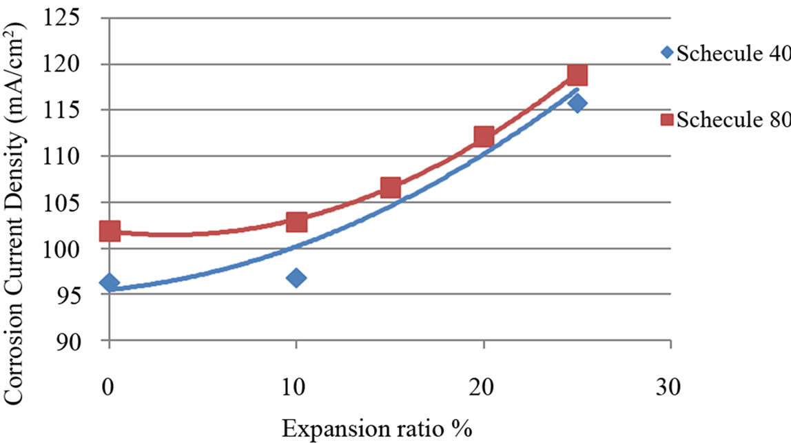
Figure 8. Corrosion current density vs. expansion ratio.
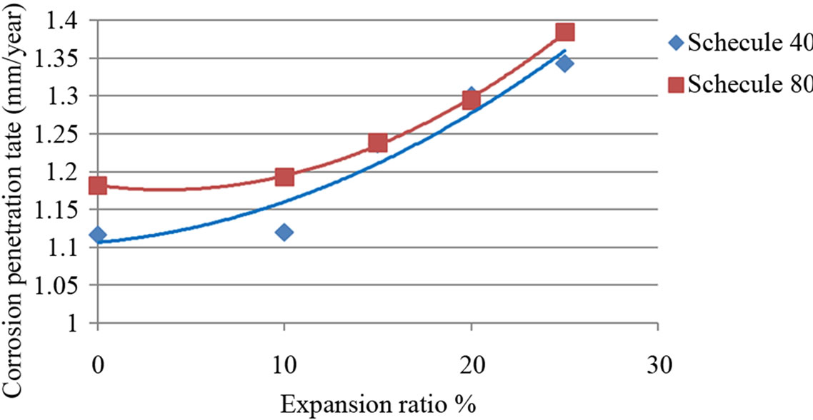
Figure 9. Corrosion rate vs. expansion ratio.
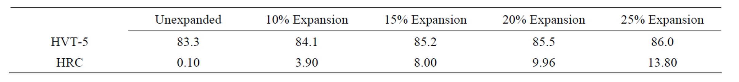
Table 2. Vickers and rockwell C hardness measured at the outer surfaces of the pipes.
The grain size numbers of the schedule 40 steel samples are calculated using the intercept method (Equations (6) and (7)) for the grain structures shown in Figures 10-14. The obtained results are summarized in Table 3 where the obvious enlargement in grain sizes that were observed under the microscope is validated. It can be seen
 (a)
(a)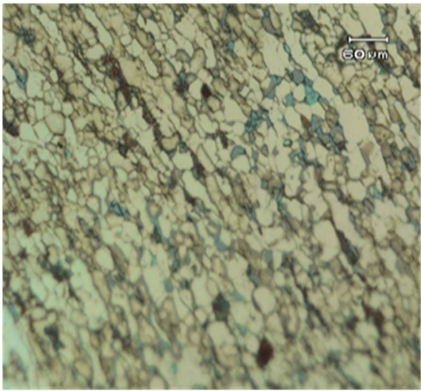 (b)
(b)
Figure 10. Surface microstructure of outer tube shell of schedule 40 before expansion. (a) Microscope 100×; (b) SEM.
 (a)
(a)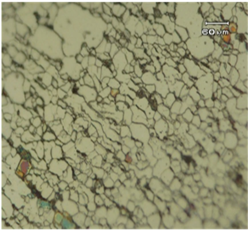 (b)
(b)
Figure 11. Surface microstructure of outer tube shell of schedule 40 after 10% expansion. (a) Microscope 100×; (b) SEM.
 (a)
(a)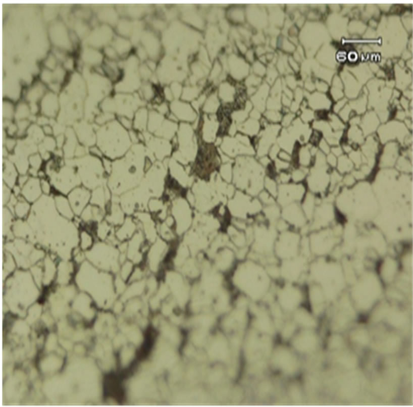 (b)
(b)
Figure 12. Surface microstructure of outer tube shell of schedule 40 after 15% expansion. (a) Microscope 100×; (b) SEM.
 (a)
(a)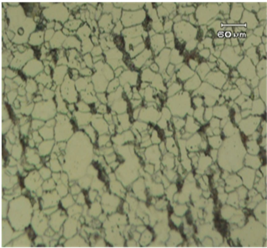 (b)
(b)
Figure 13. Surface microstructure of outer tube shell of schedule 40 after 20% expansion. (a) Microscope 100×; (b) SEM.
 (a)
(a)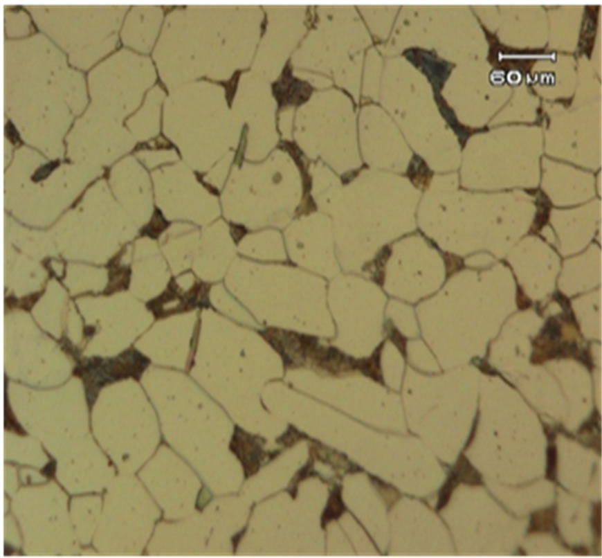 (b)
(b)
Figure 14. Surface microstructure of outer tube shell of schedule 40 after 25% expansion. (a) Microscope 100×; (b) SEM.
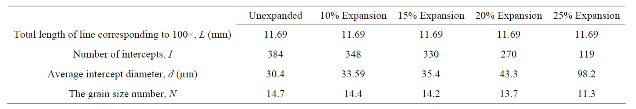
Table 3. Average intercept diameter corresponding to 100×.
that the grain size number decreases as the expansion ratio increases indicating that the grains get enlarged and elongated for higher expansion ratios.
5. Conclusion
A comprehensive experimental study dealing with the corrosion and microstructure behaviors of expanded Cr-Mo steel tubes was conducted. The experimental results revealed a good correlation between the corrosion rate and surface microstructure changes of expanded tubes. In general, it was observed that the steel tubes are more susceptible to corrosion at higher expansion ratios. This was found to be related to grain size enlargement and rearrangement. Further study on the stress corrosion rate of expanded tubes will be conducted shortly.
REFERENCES
- Z. Ahmad, “Principles of Corrosion Engineering and Corrosion Control,” Butterworth-Heinemann, Burlington, 2006, pp. 9-14. HUdoi:10.1016/B978-075065924-6/50003-9U
- C. A. Apostolopoulos and D. Michalopoulos, “The Impact of Corrosion on the Mechanical Behavior of Steel Undergoing Plastic Deformation,” Materials and Corrosion, Vol. 58, No. 1, 2007, pp. 5-12. HUdoi:10.1002/maco.200603978U
- C. A. Apostolopoulos and D. Michalopoulos, “Impact of Corrosion on Mass Loss, Fatigue and Hardness of BSt500s Steel,” Journal of Materials Engineering and Performance, Vol. 16, No. 1, 2007, pp. 63-67.
- E. M. Gutman, V. I. Storonskii and G. V. Karpenko, “Corrosion of Deformed Boiler Steel in Flushing Solutions,” Fiziko-Khimicheskaya Mekhanika Materialov, Vol. 4, No. 3, 1968, pp. 324-329.
- A. C. Seibi, S. Al-Hiddabi and T. Pervez, “Structural Behavior of a Solid Tubular Under Large Plastic Radial Expansion,” Journal of Energy Resources & Technology, Vol. 127, No. 4, 2005, pp. 323-326.
- D. A. Jones, “Principles and Prevention of Corrosion,” 2nd Edition, Prentice-Hall Inc., Upper Saddle River, 1996, p. 146.
- L. Yang, “Techniques for Corrosion Monitoring,” Woodhead Publishing Limited and CRC Press LLC, Cambridge, 2008, pp. 58-64.
- W. F. Hosford, “Materials Science: An Intermediate Text,” Cambridge University Press, New York, 2007, p. 1.
- M. A. Al-Anezi, G. S. Frankel and A. K. Agrawal, “Susceptibility of Conventional Pressure Vessel Steel to Hydrogen-Induced Cracking and Stress-Oriented HydrogenInduced Cracking in Hydrogen Sulfide-Containing Diglycolamine Solutions,” Corrosion, Vol. 55, No. 11, 1999, pp. 1101-1109.
NOTES
*Corresponding author.