Circuits and Systems
Vol.09 No.12(2018), Article ID:89489,11 pages
10.4236/cs.2018.912019
A Temperature-Based Hysteresis Buck Converter for Dynamic Current Sharing
Longkai Zhang1, Hongchong Wu1, Chinghwa Cheng1, Dongey Liu1, Miinshyue Shiau2*, Weidian Lai2, Ziwei Zheng2
1Department of Electronic Engineering, Feng Chia University, Taiwan
2Department of Electronic and Information Engineering, Xiamen City University, Xiamen, China

Copyright © 2018 by authors and Scientific Research Publishing Inc.
This work is licensed under the Creative Commons Attribution International License (CC BY 4.0).
http://creativecommons.org/licenses/by/4.0/


Received: November 26, 2018; Accepted: December 24, 2018; Published: December 27, 2018
ABSTRACT
In this study, a temperature-based current sharing strategy rather than equal sharing for loads was applied to promote the reliability of uninterruptible power systems (UPS). According to the temperature of each power supply module in a UPS, it would be better to reduce the output current ratio for a hotter supply module in the UPS. In this design, we implemented our regulation circuits by the UMC 0.25-μm CMOS technology with an input range from 3 V to 4.2 V and the regulated output at 1.1 V. The rated output current was 100 mA for each phase. We also employed a current-mode error-correction circuit to improve the current sharing performance based on the averaged current of each phase at the same temperature. According to our simulation results, the current sharing error can be restricted within ± 5% for the supply modules at the same temperature in our system.
Keywords:
Load Current Sharing, Uninterruptible Power Systems, UPS, Voltage Regulator, Temperature-Based Sharing

1. Introduction
For heavy-load power supply systems, a system with multiple power supply modules connected parallelly may provide several advantages [1] [2] [3] . With this configuration, it can support a heavier load by a group of smaller modules; this configuration has redundant characteristics such that the reliability of this system would be promoted. Therefore, it is often preferred in UPSs for heavy load situations, such as computer servers. For this configuration, the challenge in the design of the power supplies comes to the design of current sharing function to ensure each power supply works correctly. There are many current sharing methods proposed in recent years, such as the droop or average current method [4] . But the droop method suffers poor transfer efficiency. On the other hand, it needs an extra current reference for the average current method which makes the circuit more complex.
Recently, a simple current sharing method was proposed for multiphase voltage control to achieve good current sharing performance [5] without the current reference. They employed multiple power modules to supply a stable voltage output. The primary challenge in design of parallel power supplies is its current sharing performance. For practical considerations, the power supplies in UPS suffer different thermal effects while sharing the load current equally. This fact would degrade the lifetime of the power supply with a higher temperature in this system. In our design, we proposed an additional auxiliary circuit to solve this problem to achieve more reliable current sharing performance.
The thermal effect in UPS arises from the fact that the temperature of the power supply module on the top of a power shelf is usually higher than the bottom one. Because of the thermal convection, the generated heat from all the power supplies would accumulate at the top in the shelf. Therefore, the top module suffers higher temperature than the others. If all the power modules share the same current output, the module suffering higher temperature would exhibit poor reliability. According to general phenomena, the failure rate of a power device would get doubled for every 10˚C increase in temperature. Therefore, the reliability of the whole power system would degrade 50% in life time even with only one power supply getting its temperature raised by 10˚C. To solve this problem, we proposed a method by detecting the temperature of each power module in each phase to redistribute the current ratio. With this scheme, the hot power module supply would share a lower current to cool down itself with an aim to achieve a better balance of the failure rate for each module in the UPS.
2. Circuit Design
The circuit structure was revised from the basic circuit proposed in [5] . Figure 1 shows the chip function blocks. Figure 1(a) illustrates two power supply modules to share a common load, RLOAD. Figure 1(b) depicts the circuit details of a power supply module. In addition to the basic structure in [5] , we added some functions, such as an auxiliary circuit to achieve better current sharing performance; and a temperature based current sharing controller for better reliability balance of a UPS. The following sub-sections will discuss the details of these function circuits.
2.1. Current Sharing Method
For conventional designs, the average current sharing method and the droop current sharing method are usually employed. Figure 2 shows the scheme of the
 (a)
(a)
 (b)
(b)
Figure 1. Schematics of (a) the configuration of power supply modules; (b) the function blocks of a power supply module.

Figure 2. Scheme of the multi-phase current sharing method.
N-phase current sharing method purposed by [5] . In our study, we would add a thermal controller and an error correction circuit as in Figure 1(b) to modify the sharing ratio at different temperatures.
In our study, only 2 phases were employed. Unlike the conventional sensing of the load current through a small resistor, in our circuit, the current information at the load was directly sensed at each phase. After comparison, our circuit would turn on the phase with the lower current if the two modules were at the same temperature. The advantage of this sharing method is that its response would be faster. In the meanwhile, the disadvantage of this scheme is that it would generate an error between the sharing currents of the two phases due to the turn-on times of the two phases were different. For this issue, the output current of each module will revise when the error accumulated over the ripple in the load current. The criterion to change the sharing ratio will be discussed in the later section.
Taking the circuit in Figure 2 as a two-phase dc-dc converter structure as the example, the operation waveform can be depicted in Figure 3. When the output VFB, it also is the feedback voltage, approached the lower limit of the hysteresis window, VTL, the control signal CMAIN will be set high to turn on the selected power supply. By sensing the current of each phase, this circuit needs to deter

Figure 3. Waveforms of the current sharing of a two-phase system from Figure 2.
mine which phase provides lower current. By a control scheme to turn on the suitable module, a reliable current sharing can be achieved. Our design of the control scheme will be described in the next section.
2.2. Current Correction Scheme
In the design of the current error correction circuit, we have to know how much error will generate at each switching cycle. According to the error, the turn-on time of the power supply module having lower current phase need to be extended. And the turn-on time of the module having higher output current should be reduced.
In our circuit, the error of between the currents of the two phases in each switching cycle was estimated. After the accumulated current error was higher than a criterion, the controller would trigger the correction circuit to change the turn-on times for both phases. Figure 4 illustrated the currents of the two phases before correction. In this figure, the accumulated error can be up to 20 mA.
In our study, when one phase supplied more current than the other one, its current would be reduced by decreasing its turn-on time. For this purpose, we designed an auxiliary current source to help the decreasing process faster. The auxiliary current source is marked by the block in Figure 5. The control circuit is shown in Figure 6 [6] [7] .
As seen in Figure 5 and Figure 6, when a phase supplies more current to the load, the auxiliary current source will react to reduce the on time. For this purpose, we needed the auxiliary current source to sense the current information of each phase. In our design, the current information of each phase was sampled by directly coupling the current to charge a capacitor within a sampling cycle [8] . This sampling cycle was set to be two switching cycles which would cover the same one switch-on and three times of switching off for both phases. Based on the design of a two-phase power supply from Figure 2, the current sampling circuit and driving circuit for the auxiliary current source was included in our circuit and is illustrated in Figure 6.
2.3. Simulation at the Same Temperature
The simulation results of this circuit without and with the correction circuit can be seen in Figure 7 and Figure 8, respectively. By comparing the errors in both

Figure 4. Accumulation of current error without error correction circuit.

Figure 5. Auxiliary current source.

Figure 6. Current sampling and control circuit for the auxiliary current source.
figures, it can be found that the current sharing performance is improved significantly with the help of the auxiliary circuit. According to this simulation results, the current sharing error can be restricted within ± 5% in our system. Due to the correction scheme, the auxiliary circuit can reduce output noises which can be caused by large current drop in each phase without the correction scheme.
2.4. Temperature-Based Current Sharing Control
In our study, the conventional design of the power supply module to equally share the load current is not ideal for practical operations. In practical applications,

Figure 7. Waveforms of the two output currents for a load current of 50 mA without the auxiliary circuit.
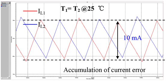
Figure 8. Waveforms of the two output currents of our circuit with the auxiliary circuit for a load current of 50 mA.
the reliability of an electronic device, especially for a power device, is closely related to the thermal effect. Since the temperatures of the power modules are different in a power case due to the non-uniform distribution of heats accumulated by all the power modules in the case. Therefore, every power module suffers different temperature even they share the load equally. In our study, we would like to propose a new scheme of current sharing control depending on itself temperature of a power module. In the control circuit, the load of a power supply module having higher temperature was reduced by decreasing its turn-on time such that the reliability of the whole system can be extended significantly. Therefore, the current sharing scheme was no longer just 50% for both phases. Instead, the sharing ratio of each module would change depending on the temperature of itself.
To achieve this object, a circuit sensing the temperature of each phase was proposed as shown in Figure 9. In this figure, the BJT is employed as the temperature sensor for each phase. Its emitter current is a function of the temperature. By compare the temperature sensitive current which reflects the temperature of each phase, the phase at the higher temperature would be determined.

Figure 9. Temperature sensing circuit.
To redistribute the current sharing ratio for each phase of different temperature, an addition control signal relevant to the temperature information of each phase was required.
To achieve this target, the current difference affected by the temperature was utilized at the input of the current comparator in Figure 6. As seen in Figure 1(a), the feedback VFB is cross coupled from the other module. With this mechanism of cross-coupled feedback, the input currents, ISENSE1 and ISENSE2, at the input of the current comparator will approach to be the same such that the two modules would share the same load current.
In order to change the ratio between ISENSE1 and ISENSE2 and according to the temperature difference between the two power modules, we added two additional currents, IDISCH1 and IDISCH2, as in Figure 6 before the current comparator. The additional IDISCH1 and IDISCH2 are temperature dependent mirrored currents from the temperature sensing circuits of the two phases as shown in Figure 9. With this design, our circuit will make ISENSE1 and ISENSE2 unequal if the temperatures of the two phases are different. The effect of temperature dependent IDISCH on the sensing current ISENSE and the load current IL is depicted in Figure 10. In addition, the operating waveforms of these signals are shown in Figure 11.
3. Results and Discussion
In this study, we designed our circuit based on UMC 0.25 μm 2P3M CMOS technology. As seen in Figure 1, the input voltage, VIN, was selected in the range from 3 V to 4.2 V. The regulated output voltage, VOUT, of each phase was set at 1.1 V. The switching frequency at no load was 250 KHz. The maximum output current, ILOAD over RLOAD was 100 mA. The switching frequency was changed depending on the load current which was determined by the inductors, L1 and L2, and the output capacitors CL1 and CL2. In this design the inductors were selected as 300 μH, the output capacitors 10 μF and the output resistors 8 Ω, respectively. Figure 12 demonstrates the waveforms of the output currents and the switching control in a scenario that the load current changed from a light load of

Figure 10. Effect of the additional current, IDISCH, on the current sharing at the load.

Figure 11. Operating waveforms of the sensing currents ISENSE1 and ISENSE2 and the load currents IL1 and IL2 due to an additional current of 1 μA between IDISCH1 and IDISCH2.
20 mA to the middle load, 100 mA. Figure 13 demonstrates the transient waveforms from the same middle load to the light load, 20 mA. According to both results, the stability of our system can be confirmed for switching between different load currents.
Figure 14 and Figure 15 show the balanced waveforms for both modules at two different temperatures. In this case, we set the total load current as 50 mA. In Figure 14, the phase 1 has a lower temperature than that of the phase 2, one can notice that the output current of module 2 would increase up to 30 mA to share more loadings. In the meanwhile, phase 2 having a higher temperature may share a lighter load which would reduce the increasing rate of its temperature. The case with the two temperatures of both modules interchanged was also verified for its symmetrical operation. In Figure 15, the same data can be found but interchanged for phase 2 has a lower temperature. According to both figures, the temperature-dependent control in our circuit was also confirmed. Since the

Figure 12. Transient response of the load currents from 20 mA to 100 mA.

Figure 13. Transient response of the load currents from 100 mA back to 20 mA.
temperature of the phase offering larger current would increase faster than that of the other one, the ultimate result may be the case that the temperatures of

Figure 14. Waveforms of the balanced output currents with a presumption for phase1 at 25˚C, phase 2 75˚C.

Figure 15. Waveforms of the balanced output currents with a presumption for phase1 at 75˚C, phase 2 25˚C.
both modules approach to almost the same to each other. In this case, the output current would be equivalently shared by both modules. Therefore, it can be expected that the reliability of the multiphase power supply can be improved significantly.
4. Conclusion
In this paper, we propose a new current correction circuit to improve the current sharing performance. In addition, the temperature effect is also considered by a temperature sensing circuit to redistribute the current ratio for the power modules. In our circuit, the hotter power supply would share lower ratio for the load current for better thermal balance. Since the unbalanced current sharing is affected by the temperature difference, the whole system may arise another feedback mechanism between the load sharing ratio and the temperature difference. It is of theoretical interests to investigate on the interaction between the current ratio and the temperature difference for practical systems. In our primary figuring, since the temperature changes very slow, it was expected that the ultimate condition is the temperature difference reduced to 0. Nevertheless, the temperature-based sharing is beneficial for the lifetime of a power system. For heavy load applications, it is promising in our study that the parallel connected multiple phase power supply with temperature-base sharing can be feasible.
Acknowledgements
The technical support from UMC Inc. is appreciated. And the financial support of Department of Electronic and Information Engineering, Xiamen City University is also acknowledged.
Conflicts of Interest
The authors declare no conflicts of interest regarding the publication of this paper.
Cite this paper
Zhang, L.K., Wu, H.C., Cheng, C., Liu, D., Shiau, M., Lai, W.D. and Zheng, Z.W. (2018) A Temperature-Based Hysteresis Buck Converter for Dynamic Current Sharing. Circuits and Systems, 9, 213-223. https://doi.org/10.4236/cs.2018.912019
References
- 1. Shiau, M.-S. and Hung, C.-C. (2017) Switching Power Supply Apparatus that Incorporate the Same. US Patent No. 9698702B1.
- 2. Nesgaard, C. and Andersen, M.A.E. (2004) Optimized Load Sharing Control by means of Thermal Reliability Management. 35th Annual IEEE Power Electronics Specialists Conference, 6, 4901-4906. https://doi.org/10.1109/PESC.2004.1354866
- 3. Nesgaard, C. and Andersen, M.A.E. (2004) Efficiency Improvement in Redundant Power Systems by Means of Thermal Load Sharing. Applied Power Electronics Conference and Exposition, 1, 433-439.
- 4. Shuai, Z., Mo, S., Wang, J., Shen, Z.J., Tian, W. and Feng, Y. (2016) Droop Control Method for Load Share and Voltage Regulation in High-Voltage Microgrids. Journal of Modern Power Systems and Clean Energy, 4, 76-86. https://doi.org/10.1007/s40565-015-0176-1
- 5. Abu-Qahouq, J., Mao, H. and Batarseh, I. (2004) Multiphase Voltage-Mode Hysteretic Controlled DC-DC Converter with Novel Current Sharing. IEEE Transactions on Power Electronics, 19, 1397-1407. https://doi.org/10.1109/TPEL.2004.836639
- 6. Solis, J.E.M., Navarro, M.G., Mejia, I., Lozano, R.Z.G., Rojas, F.L., Hidalgo, J.O. and del Toro, H.B. (2016) Low Input Resistance CMOS Current Comparator Based on the FVF for Low-Power Applications. Canadian Journal of Electrical and Computer Engineering, 39, 127-131.
- 7. Hsu, W.J. (2015) Single-Inductor Dual-Buck-Output DC-DC Converter Using Constant On-Time Based on Power-Distributive Control. Master Thesis, Institute of Electronic Engineering, Feng Chia University, Taiwan.
- 8. Chen, J.-J., Lin, Y.-T., Lin, H.-Y., Su, J.-H., Chung, W.-Y., Hwang, Y.-S. and Tseng, C.-L. (2005) On-Chip Current Sensing Techniques for Hysteresis Current Controlled DC-DC Converters. Electronics Letters, 41, 95-97. https://doi.org/10.1049/el:20056807