Circuits and Systems
Vol.07 No.02(2016), Article ID:63472,8 pages
10.4236/cs.2016.72005
Matrix Operations Design Tool for FPGA and VLSI Systems
Semih Aslan1, Jafar Saniie2
1Ingram School of Engineering, Electrical Engineering, Texas State University, San Marcos, TX, USA
2Department of Electrical and Computer Engineering, Illinois Institute of Technology, Chicago, IL, USA

Copyright © 2016 by authors and Scientific Research Publishing Inc.
This work is licensed under the Creative Commons Attribution International License (CC BY).
http://creativecommons.org/licenses/by/4.0/


Received 15 January 2016; accepted 14 February 2016; published 17 February 2016
ABSTRACT
Embedded systems used in real-time applications require low power, less area and high computation speed. For digital signal processing, image processing and communication applications, data are often received at a continuously high rate. The type of necessary arithmetic functions and matrix operations may vary greatly among different applications. The RTL-based design and verification of one or more of these functions could be time-consuming. Some High Level Synthesis tools reduce this design and verification time but may not be optimal or suitable for low power applications. The design tool proposed in this paper can improve the design time and reduce the verification process. The design tool offers a fast design and verification platform for important matrix operations. These operations range from simple addition to more complex matrix operations such as LU and QR factorizations. The proposed platform can improve design time by reducing verification cycle. This tool generates Verilog code and its testbench that can be realized in FPGA and VLSI systems. The designed system uses MATLAB-based verification and reporting.
Keywords:
FPGA, VLSI, Matrix Operations, Design Tools, MATLAB

1. Introduction
Today, a significant number of embedded systems are focused on multimedia applications, and the demand for low cost, high performance and low power hardware is almost insatiable. The design of complex systems such as image and video processing, compression, face recognition, object tracking, 4G modems, multi-standard CODECs, and HD decoding schemes requires integration of many complex blocks and a long verification process [1] . These complex designs are based on I/O peripherals, one or more processors, bus interfaces, A/D, D/A, embedded software, memories and sensors.
Image and video processing applications require a large amount of data transfers between the input and output of a system. Data are constantly transferred, altered and stored during processing. To ensure correct operation and data transfer, a control block needs to be designed carefully. Designing an image and video processing unit can be complex and time consuming, and the verification process can take months depending on the system’s complexity.
System-on-chip (SoC) designs are mainly accomplished by using Register Transfer Languages (RTL) such as Verilog and VHDL. An algorithm can be converted to RTL level using the behavioral model description method or by using pre-defined IP core blocks. After completing this RTL code, formal verification must be done before implementation. After implementation of the RTL code, timing verification needs to be done for proper operation. RTL design abstracts logic structures, timing and registers [2] . Because of this, every clock change causes a state change in the design. This timing dependency causes every event to be simulated. This results in a slower simulation time and longer verification period of the design.
RTL description of a system can be implemented from a behavioral description of the system in Perl or C. This will result in a faster verification process and shorter Time-to-Market (TTM). It is also possible to have a hybrid design where RTL blocks can be integrated with High Level Synthesis (HLS).
The HLS design flow can be used to represent the whole system or parts of a system using one of the high level languages such as Perl, C, C++, Java, MATLAB [3] . Each part in the system can be tested independently before the whole system is tested. After the verification process, the design can be implemented using FPGA synthesis tools.
The proposed matrix operations design (MOD) tool focuses on basic and advanced matrix operations for improved design and verification times. Required background information is described in Section 2 and the design and examples error analysis are discussed in Section 3.
2. Background
Basic and advanced matrix operations are required in many complex algorithms in digital, image and video processing applications. Most of the time these matrix operations are performed using a conventional (also known as traditional) method used in basic algebra classes. The conventional methods to perform addition and multiplication operations are used to implement matrix multiplications for small matrices. If a large matrix multiplication is needed, many systems use software. Due to the development of VLSI and FPGA technologies, however, the computational power of the systems has increased and massive amount of data need to be pro- cessed at a very high speed. With that in mind, the realization of a high speed, low power and low area real time matrix multiplication system for large matrices is desirable. The idea behind the MOD tool is to give designers options based on area and speed optimization and faster TTM. The components of the MOD tool are shown in Figure 1.
The proposed MOD tool has four important principles:
Compute required matrix operation(s);
Customized range and accuracy;
Generate an area-efficient, fast system for low power applications;

Figure 1. Matrix Operations Design (MOD) block.
Perform verification on the fly. Create testbenches for pre- and post-verification.
The MOD tool accepts inputs from the user via a console and includes the following sections:
FPGA or ASIC support;
Vendor based IP Core support;
Project Name (default is c:\MOD\MOD);
Top Module Name (default is MOD);
Language―Verilog HDL (up to 64-bit fixed point);
Signed or unsigned number systems;
Target―Frequency, area, and throughput optimization;
Testbench generation.
o Automated testbench with MATLAB;
o Modelsim: do file for fast automation;
o Automated testbench file for Modelsim;
o Error comparison with MATLAB;
o User defined test data option.
The “Matrix Operations” GUI shown in Figure 2 has the following sections:
Any size square matrix operations (verification is limited to computer memory size);
Basic matrix operations.
o Addition/Subtraction (Area or speed optimized based on RCA or CLA);
o Multiplication (Traditional or Strassen, Hybrid is future addition).
Advanced matrix operations.
o Matrix inverse-LU factorization, QR factorization, Cholesky factorization or Strassen based design;
o Symmetric matrices;
o Hessenberg matrices-Householder based design;

Figure 2. Matrix operations console GUI for MOD.
o LU factorization-Reduced LU factorization;
o Cholesky factorization-Positive definite matrices;
o QR factorization-Householder (Givens rotation or Gram-Schmidt based design are future addition);
o Solution to linear equation-LU, Cholesky, or QR factorization based design;
o Eigenvalue calculations-QR method design;
o Curve fitting-QR factorization based design (future addition).
The MOD tool uses a bottom-up design process that starts with the advance matrix operations and then moves to the simplest arithmetic operations. This is shown in Figure 3.
This design flow contains the following procedure: First, selection of a QR factorization algorithm, advanced matrix operations, matrix operations [4] [5] and basic arithmetic operations, and generation of area efficient hardware for FPGA and VLSI. There are two 64-bit selections that are suitable for a vast array of applications with the requested precision. The section’s addition and multiplication are used based on the previous designs. Selection of the matrix operations is done using a traditional method, Strassen algorithm [4] or hybrid method. The selection is based on matrix size. This area-efficient design is optimized for speed by implementing a smart control system. For performance evaluation and synthesis, the QR algorithm is implemented with Xilinx FPGAs [6] and VLSI using Microwind Design Tools [7] .
3. Matrix Operations
Some of the important matrix operations and algorithms used by the MOD tool are explained below.
3.1. Matrix Addition/Subtraction
The MOD tool uses conventional matrix addition/subtraction for this operation. Designers can select CLA or RCA-based addition based on optimization selection that is done in Figure 2.

Figure 3. The MOD tool design flow.
3.2. Matrix Multiplication
Matrix multiplications [4] [8] [9] are heavily used in many communication, signal and image processing applications. Matrix multiplication requires operation elements (OE) such as addition and multiplication. In matrix multiplication, the number of OEs depends on the matrix size. This made it difficult to implement real time matrix multiplication. The traditional method is one of the main methods used due to its simplicity to implement. It has operation complexity (multiplication operation) O(n)3 where n is the size of the matrix. This complexity measure is acceptable for designs with smaller N. The method introduced by Strassen [10] reduced the operation complexity to O(n)2.807 [9] [10] . Even though this difference is minimal, it makes a big difference in matrices for larger n. The MOD tool uses the traditional method or Strassen method.
Traditional Method: Matrix multiplication of an m × r matrix A and r × n matrix B produces a m×n matrix C [4] .
Strassen Method: The Strassen algorithm was introduced by Volker Strassen in 1969. Currently, this is not the fastest known algorithm but it is the one of the fastest algorithms that can be implemented in hardware for large matrices.
3.3. LU Factorization
One of the most important matrix factorizations for preconditioning is the A = LU factorization where a matrix A is factored into the product of two matrices, L is a lower triangle matrix and U is an upper triangle matrix. The LU factorization is an important factorization for solving linear equations, calculation of inverse matrices and many more important matrix-related operations that can be used in DSP and image processing. In a given matrix A, LU transformation can be written as A = LU where L and U are lower and upper right triangle matrices, respectively. Some of the LU transformations are the Gaussian elimination method, direct decomposition and the Cholesky factorization. The MOD tool uses LU factorization over Gaussian elimination. LU factorization can solve linear equations simultaneously and this will be suitable for high data I/O DSP systems.
3.4. QR Factorization
The QR matrix transformation is commonly used in DSP and wireless communication designs [11] [12] . Using this transformation, a matrix A can be factored into A = QR where Q is an orthogonal matrix (square matrix that has orthonormal columns), and where R is an upper right triangular matrix. There are a few different techniques used to transform matrix A. The ones most commonly used are the Householder transformation [13] , Givens Rotations and Gram-Schmidt QR-Decomposition.
The main idea behind QR transformation is to translate matrix A into orthogonal matrix Q and right triangle matrix R. An orthogonal matrix has a property of QTQ = I. where
Q: Orthogonal matrix;
QT: Transpose of Q;
I: Identity matrix.
A set of vectors  is orthogonal if and only if
  when i ≠ j. If an orthogonal set has a norm of 1 it is said to be orthonormal. This is an important definition of a clear QR transformation. The MOD tool uses the Householder-based QR factorization. The Householder algorithm that is implemented as hardware is shown in Figure 4.
3.5. Matrix Inversion
The other important matrix operation that is used in many important DSP and image processing applications is the inverse of a matrix. A square matrix A and its inverse A-1 can be written as AA−1 = I iff det(A) ≠ 0 where I is the identity matrix. The inverse of a matrix is an important part of the calculation of many matrix transformations and the solution of linear equations. Unfortunately, calculation of a matrix inverse similar to matrix multiplication requires many addition and multiplication operations and may be costly to implement hardware level for large matrices. Hardware implementation of matrix inverse is an important part of the MOD. The MOD can design area efficient matrix inverse hardware using a few different techniques. These techniques are improved here for area efficiency or speed based on the required design parameters. The matrix inverse algorithms used in the MOD are an LU factorization-based inverse system. A block diagram of Matrix inversion using LU transformation is given in Figure 5.
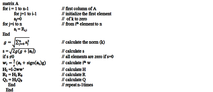
Figure 4. The householder QR factorization algorithm.

Figure 5. Matrix inversion using LU transformation.
The MOD tool can design and validate a system of linear equations using a couple different methods similar to ones that are explained above in the matrix inversion section. Due to similarities between solutions to linear equations and matrix inversion, further hardware reduction can be done by reusing similar sections of the hardware to design a system that can solve a linear equation and can also be used for matrix inversion. A system of linear equations shown in Equation (1) can be solved using LU factorization.
 (1)
(1)
 . (2)
. (2)
Using Equations (1) in (2), a system of linear equation can be described as in Equation (3) and using forward substitution in Equation (4), and back substitution in Equation (5) variables x can be calculated by.
 (3)
(3)
 (4)
(4)
 . (5)
. (5)
A similar solution system can be used if QR factorization is available.
4. Design Results
The MOD design system allows for fast TTM and higher accuracy. The system uses the same verification method for FPGA and VLSI that is shown in Figure 6.
The MOD design system can design Verilog HDL code and a testbench file of any size matrix operations, subject to limitation of the MATLAB version, computer memory and hard drive size. The design creates a MATLAB file for verification and error analysis.
One of the great advantages of the MOD design and verification system is the ability to change size and

Figure 6. The MOD verification flow.
optimization of the design in a minimal amount of time. Designers can compare many designs and make decisions without spending valuable verification time.
5. Conclusion
A design tool for matrix operations is designed for low power and high-speed applications. The MOD decreases design system time and verification by up to 64% without compromising speed and efficiency. The MOD uses a smart control system that is optimized based on the desired operations, and is a bridge between RTL and HLS. It uses RTL-based basic blocks to design most complicated arithmetic operations using structural model design and HLS-style fast and optimized verification. Any designed system can be reconfigured at any time in any way in MOD without going through the same design and verification hassle. The key objective of the proposed tool is to reduce TTM and increase productivity by verifying the hardware during the design process. Future work will include support for all basic arithmetic operations, VHDL, some additional matrix factorizations, curve fitting and floating point support.
Acknowledgements
The authors would like to thank Xilinx, Inc. [6] for their valuable support.
Cite this paper
SemihAslan,JafarSaniie, (2016) Matrix Operations Design Tool for FPGA and VLSI Systems. Circuits and Systems,07,43-50. doi: 10.4236/cs.2016.72005
References
- 1. Andrieux, J., Feix, M., Mourgues, G., Bertrand, P., Izrar, B. and Nguyen, V. (1987) Optimum Smoothing of the WignerVille Distribution. IEEE Transactions on Acoustics, Speech and Signal Processing, 35, 764-769.
http://dx.doi.org/10.1109/TASSP.1987.1165204 - 2. Duncan, A. and Hendry, D. (1995) Area Efficient DSP Datapath Synthesis. Proceedings of EURO-DAC’95, European Design Automation Conference with EURO-VHDL, Brighton, 18-22 September 1995, 130-135.
- 3. (2006) The VLSI Handbook. 2nd ed. CRC Press, Boca Raton, FL.
- 4. Wang, X. and Ziavras, S.G. (2004) Parallel LU Factorization of Sparse Matrices on FPGA-Based Configurable Computing Engines. Concurrency and Computation: Practice and Experience, 16, 319-343.
http://onlinelibrary.wiley.com/doi/10.1002/cpe.748/abstract - 5. Yang, H., Ziavras, S. and Hu, J. (2007) FPGA-Based Vector Processing for Matrix Operations. Fourth International Conference on Information Technology (ITNG 07), Las Vegas, 2-4 April 2007, 989-994.
- 6. Xilinx.
http://www.xilinx.com/ - 7. MICROWIND-Home.
http://microwind.net/ - 8. Reconfigurable Computing. Elsevier.
https://www.elsevier.com/books/recon_gurable-computing/hauck/978-0-12-370522-8 - 9. SIAM: Toward an Optimal Algorithm for Matrix Multiplication.
http://www.siam.org/news/news.php?id=174 - 10. Ohtaki, Y., Takahashi, D., Boku, T. and Sato, M. (2004) Parallel Implementation of Strassen’s Matrix Multiplication Algorithm for Heterogeneous Clusters. 18th International Parallel and Distributed Processing Symposium (2004), Santa Fe, 26-30 April 2004, 112.
- 11. Yang, Y., Zhao, Y. and Inoue, Y. (2005) High-Performance Systolic Arrays for Band Matrix Multiplication. 2005 IEEE International Symposium on Circuits and Systems, ISCAS 2005, Kobe, 23-26 May 2005, 1130-1133.
- 12. Desmouliers, C., Aslan, C., Oruklu, E., Saniie, J. and Vallina, F. (2010) HW/SW Co-Design Platform for Image and Video Processing Applications on Virtex-5 FPGA Using PICO. 2010 IEEE International Conference on Electro/Information Technology (EIT 2010), Normal, 20-22 May 2010, 1-6.
- 13. Aslan, S., Oruklu, E. and Saniie, J. (2009) Realization of Area Efficient QR Factorization Using Unified Division, Square Root, and Inverse Square Root Hardware. 2009 IEEE International Conference on Electro/Information Technology (EIT 2009), Windsor, 7-9 June 2009, 245-250.