Circuits and Systems
Vol.06 No.12(2015), Article ID:61720,11 pages
10.4236/cs.2015.612026
Design of Dual-Mode Substrate Integrated Waveguide Band-Pass Filters
Ahmed Rhbanou1, Mohamed Sabbane1, Seddik Bri2
1Department of Mathematics, FSM, Moulay Ismail University, Meknes, Morocco
2Material and Instrumentations Group (MIN), Electrical Engineering Department, ESTM, Moulay Ismail University, Meknes, Morocco

Copyright © 2015 by authors and Scientific Research Publishing Inc.
This work is licensed under the Creative Commons Attribution International License (CC BY).


Received 21 October 2015; accepted 1 December 2015; published 4 December 2015

ABSTRACT
Three dual-mode band-pass filters are presented in the present paper. The first filter is realized by dual-mode substrate integrated waveguide (SIW) cavity; the second is based on the integration of SIW cavity with electromagnetic band gap (EBG); and the third is based on the integration of SIW cavity with complementary split ring resonator (CSRR). The dual-mode SIW cavity is designed to have a fractional bandwidth of 4.95% at the midband frequency of 9.08 GHz; the proposed EBG- SIW resonator operates at 9.12 GHz with a bandwidth of 4.38% and the CSRR-SIW resonator operates at 8.66 GHz with a bandwidth of 2.54%. The proposed filters have the high Q-factors and generate a transmission zero in upper stopband, and these by the use of Rogers RT/duriod 5880 (tm).
Keywords:
Substrate Integrated Waveguide, Electromagnetic Band Gap, Complementary Split Ring Resonators, SIW Cavity, Transition

1. Introduction
Rectangular waveguide filters are widely used in RF-Microwave industry, due to its characteristic properties of low losses, and high Q-factor. However, their integrations with planar structures in electronic systems are very difficult and their fabrications are expensive.
To resolve these problems, a new technology is implemented, called the substrate integrated waveguide (SIW). The SIW responds to these constraints in the design of microwave components by taking the advantages of low radiation loss, high power handling and high Q-factor.
The SIW is formed by two solid conductor planes, separated by a dielectric substrate, with conductor sidewalls emulated by rows of metalized through-plated via [1] - [10] .
On the other hand, the metamaterials (electromagnetic band gaps (EBGs) and complementary split-ring resonators (CSRRs)) are used for manipulating electromagnetic waves and the unusual properties. The application of metamaterials has allowed a great improvement the performances and the size reduction in planar microwave applications, filter, and antenna [11] - [20] .
In this paper, three dual-mode band-pass filters are proposed. These filters have been simulated in a commercial software package HFSS™, and thus a comparison was made between the proposed filters and several previous filters reported in [21] -[24] .
2. Design of SIW Cavity and Proposed Transitions
The SIW cavity enables propagation of the mode (TEm0p), its parameters necessary are the length (LSIW), the width (WSIW), the diameter D of the metallic via hole and the spacing P between the holes, which are expressed
by the resonant frequency of rectangular cavity ( ), because the electrical behavior of SIW cavity is very
close to rectangular cavity filled with the same dielectric (εr) of length (Leff) and width (Weff) as shown in Figure 1. The expression for the resonant frequency of SIW cavity:
 (1)
(1)
The size of SIW cavity is designed from the empirical Equations (1) and (2) These Equations are valid for P < 4D and P < λ0 (εr/2)1/2 with λ0 the space wavelength [1] -[9] .
 (2)
(2)
 (3)
(3)
The microstrip transition allows integration SIW to the planar structures (the planar transmission lines). Figure 2 shows the geometric structure of the proposed tapered transition. The parameters of the transition (LT and WT) and the microstrip line (WM) are expressed from the relations in [10] .
3. Design of Meta Materials (EBG and CSRR)
The electromagnetic band gap structures are presented as the complex periodic structures. The electromagnetic band gap materials are used for many applications and especially in the frequency filtering, because of their electromagnetic properties, to create band gaps in the electromagnetic spectrum. The application of EBG has allowed a great improvement the performances of numerous devices in telecommunication systems. Figure 3

Figure 1. (a) SIW resonance cavity; (b) Conventional rectangular waveguide resonance cavity.
shows the geometric structure of the proposed S-shape EBG.
Where M is the length of EBG, T is the width of EBG and V is the strip-length of EBG. The EBG is founded on the Bragg condition [11] - [15] .
On the other, the CSRR is employed as LC resonator, thus the resonant frequency is obtained by the geometric parameters of CSRR. These specific properties are adaptable for many applications and especially the filters [16] -[20] . Figure 4 shows the geometric structure of the proposed CSRR cell. With W is the ring length of CSRR, G is the gap length, A is the side-length of CSRR and F is the width which separates two rings.
4. Results
The dual-mode SIW cavity uses the substrate of Rogers RT/duriod 5880 (tm) (εr = 2.2, h = 0.508 mm and tanδ

Figure 2. SIW with tapered transitions.

Figure 3. Geometry of S-shape EBG.

Figure 4. Geometry of CSRR.
= 0.0009), with D = 0.6 mm and P = 1 mm. By considering two orthogonal modes TE102 and TE301, the size of dual-mode SIW cavity is designed from the Equation (4).
 (4)
(4)
The initial dimensions of dual-mode SIW cavity with tapered transitions have been optimized by software package HFSS™. The detailed dimensions are decided as: WSIW = 37.4 mm, LSIW = 22 mm, WM = 1.568 mm, WT = 8 mm and LT = 14.22 mm. Figure 5 shows the geometric structure of dual-mode SIW cavity with tapered transitions.
The simulation results for S-parameters of the dual-mode SIW cavity with tapered transitions are shown below in Figure 6.
Simulated results presented in Figure 6 show that the dual-mode SIW cavity with tapered transitions has the 3 dB bandwidth is approximately 0.45 GHz (from 8.855 to 9.305 GHz) centered at 9.08 GHz. The insertion loss is 0.43 dB and the return loss is better than 20 dB across the band of interest. Moreover, a transmission zeros at 9.38 GHz and the Q-factor is 414.
On the other hand, the integration of SIW cavity with EBG or CSRR allows the creation a dual-mode band-pass filter. The SIW is designed on substrate of Rogers RT/duriod 5880 (tm) (εr = 2.2, h = 0.508 mm and tanδ = 0.0009), with D = 0.6 mm and P = 1 mm. Figure 7 shows the proposed configuration of SIW-microstrip line with tapered transitions. The parameters of the proposed structure are optimized by software package HFSS™. The final desired dimensions are: WSIW = 15 mm, WM = 1.568 mm, LT = 14.22 mm and WT = 5.76 mm.

Figure 5. Configuration of dual-mode SIW cavity with tapered transitions.

Figure 6. Simulated S-parameters of dual-mode SIW cavity with tapered transitions.
For analyzing the property of S-shaped EBG, one-cell EBG is etched on the top side of SIW. The dimensions of the one-cell EBG are: M = 2 mm, T = 5 mm, V = 0.9 mm. Figure 8 shows the configuration of one-cell SIW-EBG. The simulation results for S21 parameter of standard SIW and one-cell SIW-EBG are shown below in Figure 9.
As shown in Figure 9, the structure of one-cell SIW-EBG has allowed producing a stopband at about 13.19 GHz.
On the other hand, Figure 10 shows the geometric structure of the proposed SIW resonator. The TE101- mode-based SIW cavity is presented by a square cavity with WSIW = LSIW = 15 mm and the tapered transitions with the same dimensions WT = 5.76 mm, LT = 14.22 mm and WM = 1.568 mm.
The simulation results for S-parameters of the proposed SIW resonator are shown below in Figure 11. Simulated results presented in Figure 11 show that the SIW resonator has the 3 dB bandwidth is approximately 0.34 GHz at the midband frequency of 9.11 GHz, The insertion loss is 0.371 dB and the return loss is better than 20 dB across the band of interest. Moreover, the Q-factor is 641.
To make the characteristics of proposed SIW resonator clear, the width (WSIW) is discussed in details. The simulation results for S21 parameter of the SIW resonator with different values of WSIW are shown below in Figure 12. Table 1 shows the simulation results obtained.

Figure 7. Configuration of SIW with tapered transitions.

Figure 8. Configuration of one-cell SIW-EBG.

Figure 9. Simulated transmission coefficients S21 of standard SIW and one-cell SIW-EBG.
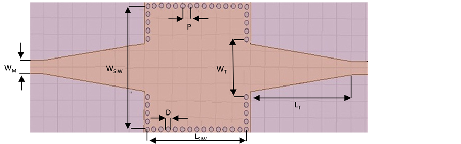
Figure 10. SIW resonator.

Figure 11. Simulated S-parameters of SIW resonator.

Figure 12. Simulated transmission coefficients S21 of SIW resonator with different values of WSIW, where LSIW = 15 mm, WT = 5.76 mm, LT = 14.22 mm, WM = 1.568 mm.

Table 1. The simulated results of SIW resonator with different values of the width (WSIW).
As illustrated in Table 1, when the width (WSIW) of SIW resonator increases the center frequency and the fractional bandwidth are decreasing, while the insertion loss becomes higher.
After studying the characteristics of SIW cavity and EBG, an EBG-SIW resonator is designed on the same substrate of Rogers RT/duriod 5880 (tm) (εr = 2.2, h = 0.508 mm and tanδ = 0.0009). Figure 13 shows the geometric structure of the proposed EBG-SIW resonator. Its physical parameters are provided in Table 2. The simulation results for S-parameters of the proposed EBG-SIW resonator are shown below in Figure 14.
Simulated results presented in Figure 14 show that the EBG-SIW resonator has the 3 dB bandwidth is approximately 0.4 GHz (from 8.92 to 9.32 GHz) centered at 9.12 GHz. The insertion loss is 1.18 dB and the return loss is better than 15 dB across the band of interest. Moreover, a transmission zeros at 12 GHz and the Q-factor is 179.

Figure 13. Geometry of EBG-SIW resonator.

Figure 14. Simulated S-parameters of EBG-SIW resonator.
Table 2. Physical parameters of proposed EBG-SIW resonator.
On the other hand, the characteristics of CSRR are analyzed, by using a simple model as shown in Figure 15, this model is formed by etching a CSRR on the top side of SIW.
In order to make the characteristics of proposed CSRR clear, its side-length (A) is discussed in details, with the same conditions as εr = 2.2, h = 0.508 mm, WT = 5.76 mm, WM = 1.568 mm, LT = 14.22 mm, WSIW = 15 mm, D = 0.6 mm, P = 1 mm. The influence of the side-length (A) is simulated and shown in Figure 16. The simulation results are shown in Table 3.
Simulated results presented in Table 3 show that the resonant frequency decreases thus the attenuation increases when the side-length of CSRR becomes increasingly larger.
After studying the characteristics of CSRR, a CSRR-SIW resonator is designed on the same substrate of Rogers RT/duriod 5880 (tm) (εr = 2.2, h = 0.508 mm and tanδ = 0.0009). Figure 17 shows the geometric structure of CSRR-SIW resonator. Its physical parameters are provided in Table 4. The simulation results for S-parameters of the proposed CSRR-SIW resonator are shown below in Figure 18.
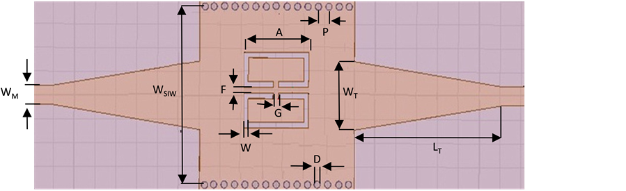
Figure 15. Configuration of one-cell SIW-CSRR.

Figure 16. Simulated transmission coefficients S21 of one-cell SIW-CSRR with different values of A, where G = 0.3 mm, F = 0.3 mm, W = 0.3 mm.
Table 3. The simulated results of one-cell SIW-CSRR with different values of the side-length (A).

Figure 17. Geometry of CSRR-SIW resonator.
Table 4. Dimensions of proposed CSRR-SIW resonator.
Simulated results presented in Figure 18 show that the proposed CSRR-SIW resonator has the 3 dB bandwidth is approximately 0.22 GHz (from 8.55 to 8.77 GHz) centered at 8.66 GHz. The insertion loss is 0.55 dB and the return loss is better than 20 dB across the band of interest. Moreover, a transmission zeros at 11.73 GHz and the Q-factor is 640.
In order to verify the characteristics of proposed filters, some comparisons between the proposed filters and several previous filters reported in the references are summarized in Table 5. According to the comparisons, the proposed filters have the advantage of high Q-factor compared to the filters in [21] -[24] .
5. Conclusions
In this paper, three dual-mode band-pass filters are proposed. The dual-mode SIW cavity filter has a center frequency of 9.08 GHz with a bandwidth of 4.95%. The insertion loss is 0.43 dB and the return loss is better than 20 dB across the band of interest. In addition, a transmission zero at 9.38 GHz and Q-factor is 414. The EBG-SIW resonator has a center frequency of 9.12 GHz with a bandwidth of 4.38%. The insertion loss is 1.18 dB and the return loss is better than 15 dB across the band of interest. In addition, a transmission zero at 12 GHz and Q-factor is 179. The CSRR-SIW resonator has a center frequency of 8.66 GHz with a bandwidth of 2.54%. The insertion loss is 0.55 dB and the return loss is better than 20 dB across the band of interest. In addition, a transmission zero at 11.73 GHz and Q-factor is 640. The simulation processes of the structures are done by using HFSS software. The design methods are discussed and presented.

Figure 18. Simulated S-parameters of CSRR-SIW resonator.
Table 5. Performance comparison among published dual-mode band pass filters and the proposed filters.
The proposed filters have a small size, high Q-factor and low loss, and can be directly integrated with other circuits without any additional mechanical assembling tuning. Additionally, these filters are easily scalable over microwave and millimeter frequency ranges.
Cite this paper
AhmedRhbanou,MohamedSabbane,SeddikBri, (2015) Design of Dual-Mode Substrate Integrated Waveguide Band-Pass Filters. Circuits and Systems,06,257-267. doi: 10.4236/cs.2015.612026
References
- 1. Cassivi, Y., Perregrini, L., Arcioni, P., Bressan, M., Wu, K. and Conciauro, G. (2002) Dispersion Characteristics of Substrate Integrated Rectangular Waveguide. IEEE Microwave and Wireless Components Letters, 12, 333-335.
http://dx.doi.org/10.1109/LMWC.2002.803188 - 2. Deslandes, D. and Wu, K. (2006) Accurate Modeling, Wave Mechanism, and Design Consideration of a Substrate Integrated Waveguide. IEEE Transactions on Microwave Theory and Techniques, 54, 2516-2526.
http://dx.doi.org/10.1109/TMTT.2006.875807 - 3. Djerafi, T. and Wu, K. (2007) Super-Compact Substrate Integrated Waveguide Cruciform Directional Coupler. IEEE Microwave and Wireless Components Letters, 17, 757-759.
http://dx.doi.org/10.1109/LMWC.2007.908040 - 4. Su, P., Tang, Z.-X. and Zhang, B. (2012) Push-Push Dielectric Resonator Oscillator Using Substrate Integrated Waveguide Power Combiner. Progress in Electromagnetics Research Letters, 30, 105-113.
http://dx.doi.org/10.2528/PIERL11122302 - 5. Huang, Y., Shao, Z. and Liu, L. (2013) A Substrate Integrated Waveguide Bandpass Filter Using Novel Defected Ground Structure Shape. Progress in Electromagnetics Research, 135, 201-213.
http://dx.doi.org/10.2528/PIER12110411 - 6. Zhang, X.-C., Yu, Z.-Y. and Xu, J. (2007) Novel Band-Pass Substrate Integrated Waveguide (SIW) Filter Based on Complementary Split Ring Resonators (CSRRS). Progress in Electromagnetics Research, 72, 39-46.
http://dx.doi.org/10.2528/PIER07030201 - 7. Xu, F. and Wu, K. (2005) Guided-Wave and Leakage Characteristics of Substrate Integrated Waveguide. IEEE Transactions on Microwave Theory and Techniques, 53, 66-73.
http://dx.doi.org/10.1109/TMTT.2004.839303 - 8. Cassivi, Y., Perregrini, L., Wu, K. and Conciauro, G. (2002) Low-Cost and High-Q Millimeter-Wave Resonator Using Substrate Integrated Waveguide Technique. The 32nd European Microwave Conference, Milan, 23-26 September 2002, 1-4.
http://dx.doi.org/10.1109/euma.2002.339390 - 9. Rhbanou, A., Bri, S. and Sabbane, M. (2015) Design of X-Band Substrate Integrated Waveguide Bandpass Filter with Dual High Rejection. Microwave and Optical Technology Letters, 57, 1744-1752.
http://dx.doi.org/10.1002/mop.29180 - 10. Deslandes, D. (2010) Design Equations for Tapered Microstrip-to-Substrate Integrated Waveguide Transitions. 2010 IEEE MTT-S International Microwave Symposium Digest (MTT), Anaheim, 23-28 May 2010, 704-707.
http://dx.doi.org/10.1109/MWSYM.2010.5517884 - 11. Kyriazidou, C.A., Contopanagos, H.F. and Alexopoulos, N.G. (2001) Monolithic Waveguide Filters Using Printed Photonic-Bandgap Materials. IEEE Transactions on Microwave Theory and Techniques, 49, 297-307.
http://dx.doi.org/10.1109/22.903089 - 12. Falcone, F., Lopetegi, T. and Sorolla, M. (1999) 1-D and 2-D Photonic Bandgap Microstrip Structures. Microwave and Optical Technology Letters, 22, 411-412.
http://dx.doi.org/10.1002/(SICI)1098-2760(19990920)22:6<411::AID-MOP13>3.0.CO;2-U - 13. Garcia-Garcia, J., Bonache, J., Gil, I., Martin, F., Marqués, R., Falcone, F., Lopetegi, T., Laso, M.A.G. and Sorolla, M. (2005) Comparison of Electromagnetic Band Gap and Split-Ring Resonator Microstrip Lines as Stop Band Structures. Microwave and Optical Technology Letters, 44, 376-379.
http://dx.doi.org/10.1002/mop.20640 - 14. Hao, Z.-C., Hong, W., Chen, J.-X., Chen, X.-P. and Wu, K. (2005) Compact Super-Wide Bandpass Substrate Integrated Waveguide (SIW) Filters. IEEE Transactions on Microwave Theory and Techniques, 53, 2968-2977.
http://dx.doi.org/10.1109/TMTT.2005.854232 - 15. Li, D., Tong, C.-M., Bao, J.-S., Peng, P. and Yu, D.-W. (2013) A Novel Bandpass Filter of Substrate Integrated Waveguide (SIW) Based on S-Shaped EBG. Progress in Electromagnetics Research Letters, 36, 191-200.
http://dx.doi.org/10.2528/PIERL12110202 - 16. Bonache, J., Gil, I., Garcia-Garcia, J. and Martin, F. (2006) Novel Microstrip Bandpass Filters Based on Complementary Split-Ring Resonators. IEEE Transactions on Microwave Theory and Techniques, 54, 265-271.
http://dx.doi.org/10.1109/TMTT.2005.861664 - 17. Dong, Y.D., Yang, T. and Itoh, T. (2009) Substrate Integrated Waveguide Loaded by Complementary Split-Ring Resonators and Its Applications to Miniaturized Waveguide Filters. IEEE Transactions on Microwave Theory and Techniques, 57, 2211-2223.
http://dx.doi.org/10.1109/TMTT.2009.2027156 - 18. O’Brien, S. and Pendry, J.B. (2002) Magnetic Activity at Infrared Frequencies in Structured Metallic Photonic Crystals. Journal of Physics: Condensed Matter, 14, 6383-6394.
http://dx.doi.org/10.1088/0953-8984/14/25/307 - 19. Baena, J.D., Bonache, J., Martin, F., Sillero, R.M., Falcone, F., Lopetegi, T., Laso, M.A.G., Garcia-Garcia, J., Gil, I., Portillo, M.F. and Sorolla, M. (2005) Equivalent-Circuit Models for Split-Ring Resonators and Complementary Split-Ring Resonators Coupled to Planar Transmission Lines. IEEE Transactions on Microwave Theory and Techniques, 53, 1451-1461.
http://dx.doi.org/10.1109/TMTT.2005.845211 - 20. Bilotti, F., Toscano, A. and Vegni, L. (2007) Design of Spiral and Multiple Split Ring Resonators for the Realization of Miniaturized Metamaterial Samples. IEEE Transactions on Antennas and Propagation, 55, 2258-2267.
http://dx.doi.org/10.1109/TAP.2007.901950 - 21. Lin, Y.-F., Chen, C.-H., Chen, K.-Y., Chen, H.-M. and Wong, K.-L. (2007) A Miniature Dual-Mode Bandpass Filter Using Al2O3 Substrate. IEEE Microwave and Wireless Components Letters, 17, 580-582.
http://dx.doi.org/10.1109/LMWC.2007.901766 - 22. Huang, X.D. and Cheng, C.H. (2006) A Novel Coplanar-Waveguide Bandpass Filter Using a Dual-Mode Square-Ring Resonator. IEEE Microwave and Wireless Components Letters, 16, 13-15.
http://dx.doi.org/10.1109/LMWC.2005.861358 - 23. Li, R.Q., Tang, X.H. and Xiao, F. (2010) Substrate Integrated Waveguide Dual-Mode Filter Using Slot Lines Perturbation. Electronics Letters, 46, 845-846.
http://dx.doi.org/10.1049/el.2010.0629 - 24. Wu, L.-S., Zhou, X.-L., Wei, Q.-F. and Yin, W.-Y. (2009) An Extended Doublet Substrate Integrated Waveguide (SIW) Bandpass Filter with a Complementary Split Ring Resonator (CSRR). IEEE Microwave and Wireless Components Letters, 19, 777-779.
http://dx.doi.org/10.1109/LMWC.2009.2033497