Circuits and Systems
Vol.5 No.9(2014), Article ID:49253,8 pages
DOI:10.4236/cs.2014.59023
Performance Analysis of Analog Butterworth Low Pass Filter as Compared to Chebyshev Type-I Filter, Chebyshev Type-II Filter and Elliptical Filter
Wazir Muhammad Laghari1, Mohammad Usman Baloch1, Muhammad Abid Mengal1, Syed Jalal Shah2
1Electrical Engineering Department, BUET, Khuzdar, Pakistan
2Computer Systems Engineering Department, BUET, Khuzdar, Pakistan
Email: niaz1111@yahoo.com, u_usman@yahoo.com, Abdulabid@gmail.com, jalalshah@buetk.edu.pk
Copyright © 2014 by authors and Scientific Research Publishing Inc.
This work is licensed under the Creative Commons Attribution International License (CC BY).
http://creativecommons.org/licenses/by/4.0/


Received 29 June 2014; revised 31 July 2014; accepted 11 August 2014
ABSTRACT
A signal is the entity that carries information. In the field of communication signal is the time varying quantity or functions of time and they are interrelated by a set of different equations, but some times processing of signal is corrupted due to adding some noise in the information signal and the information signal become noisy. It is very important to get the information from corrupted signal as we use filters. In this paper, Butterworth filter is designed for the signal analysis and also compared with other filters. It has maximally flat response in the pass band otherwise no ripples in the pass band. To meet the specification, 6th order Butterworth filter was chosen because it is flat in the pass band and has no amount of ripples in the stop band.
Keywords:Butterworth Filter, Chebyshev Filter, Elliptical Filter

1. Introduction
Filters are basically circuits to which carry out the unwanted signals or remove the noise from corrupted message signal. There are many applications of filters in the field of Telecommunication, Digital Signal Processing, Image Processing and Wireless communication etc. In the field of Digital Signal Processing, the main function of a filter is to eliminate the unwanted components from the noisy signal [1] . Suppose you send a message signal from source to destination, before reaching the signal at destination some noise is added in your message signal, so noise corrupted the message signal. A filter might be used to separate noise from original message signal. For example, a speech signal generated by transducer and due to poor performance of device some time equipment generated noise is added to an audio signal, so we apply the filter on speech signal [2] . The digital signal processing requires digital filters to getting desired signals. So it is necessary to reduce the noise of the digital signal. In this paper, we will compare the response of Butterworth filter with Chebyshev and Elliptic filter; this paper will be benefiting the reader with detailed discussion of the key design consideration of Butterworth filter.
2. Butterworth Filter
The Butterworth filter was first designed by British engineer Stephen Butterworth. Butterworth filters having a constant gain or maximally flat amplitude response in the passband and attenuation level is −3 db and −20 db [3] . The Analog design of Butterworth filter is much easier than other filter like Chebyshev and Elliptic. So when Butterworth is design in analog domain or in s-plane, it is easily converted into digital filter or z-plane. In Butterworth filter increase the order it maintains the main shape, whereas other types of filters like Chebyshev and Elliptic can not maintain the shapes at higher order. The Butterworth filter is mathematically by two parameters one is the cut off frequency and other is number of poles. The phase linearity of Butterworth filter is better than Chebyshev filter. In other words, the group delay is more constant with respect to frequency. This means rate of waveform distortion of the Butterworth filter is much lower than other filter [4] . The main application of Butterworth filters are used as tracking high frequency Low Pass Filters, smoothing filters and Antialiasing filters. The typical response of Butterworth Low Pass Filter is shown in Figure 1.
3. Chebyshev Filter
The name of Chebyshev filter is derived from Chebyshev polynomials, after Pafnuty Chebyshev. Chebyshev filters may be analog or digital filter, Chebyshev comes in two types one is called Chebyshev Type-I and other is called Chebyshev Type-II. Chebyshev Type-I filter having a steeper roll of and more passband ripple, but in Type-II stopband ripple. Chebyshev minimize the error between the ideal and actual filter characteristics, but ripples present in passband. Due to this property Chebyshev have a ripple less response in passband and more irregular response in stopband. In Chebyshev filter phase response is poor [5] . Figure 2 shows the frequency response of a low pass Chebyshev filter with different order.
If you compared Chebyshev with Butterworth, it can achieve a sharper transition band between passband and stopband. Chebyshev filter have a faster execution speeds and smaller absolute errors.
Figure 3 shows the frequency response of a low pass Chebyshev Type-II filter.
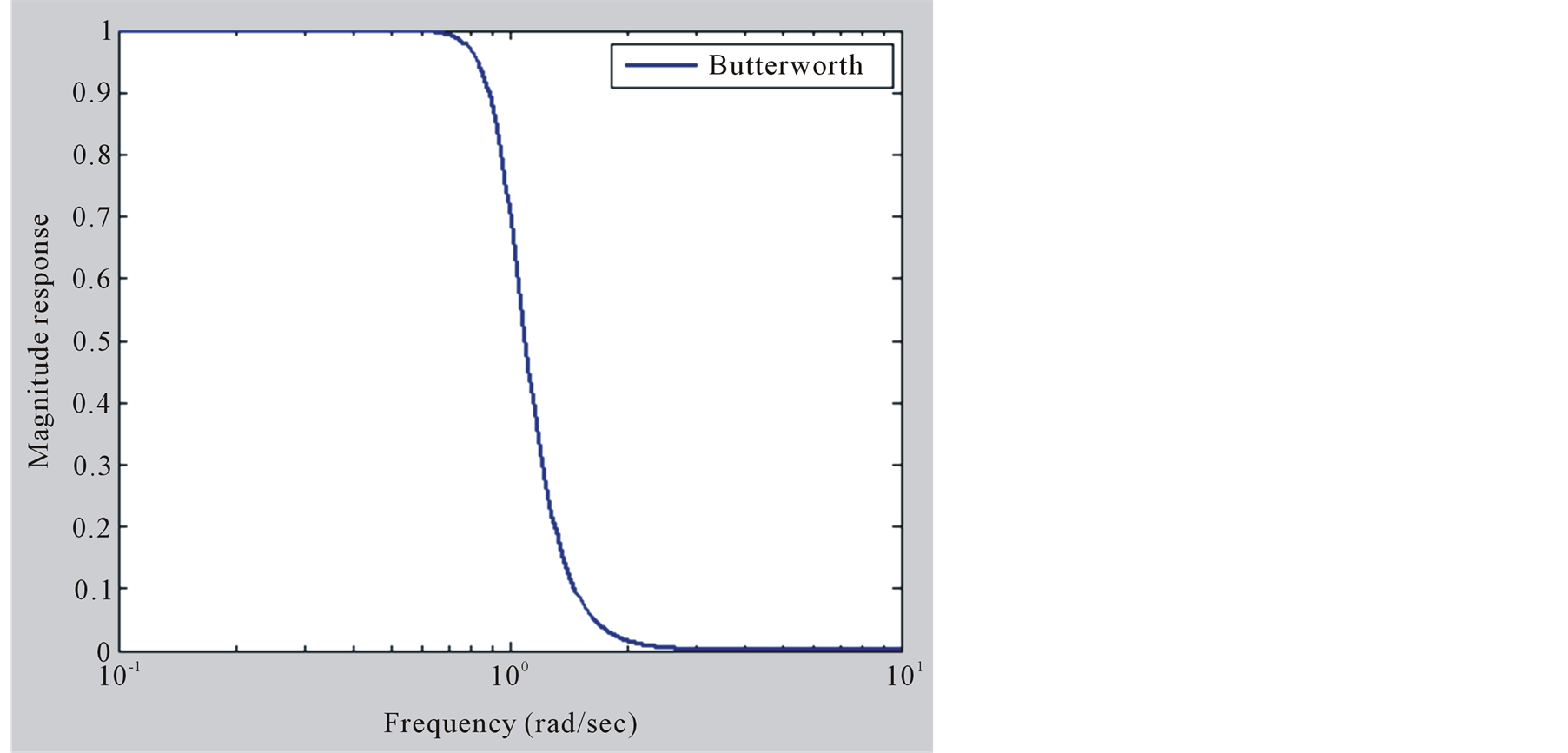
Figure 1. Frequency response of Butterworth Low Pass Filter.
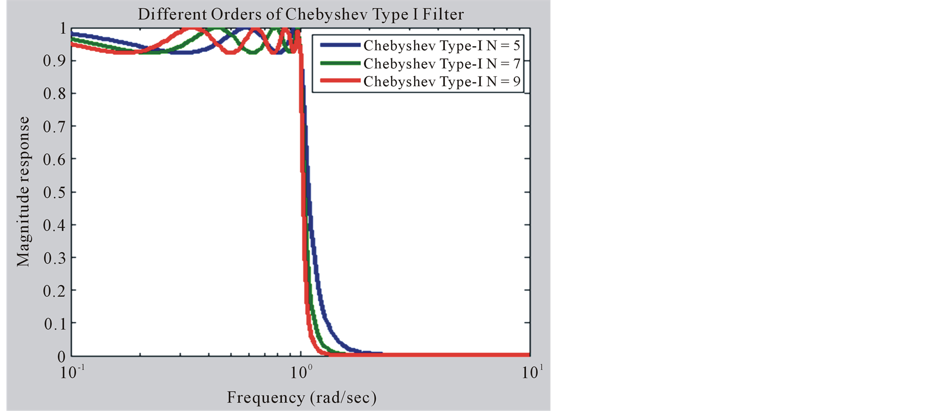
Figure 2. Frequency response of Chebyshev Type-I filter.
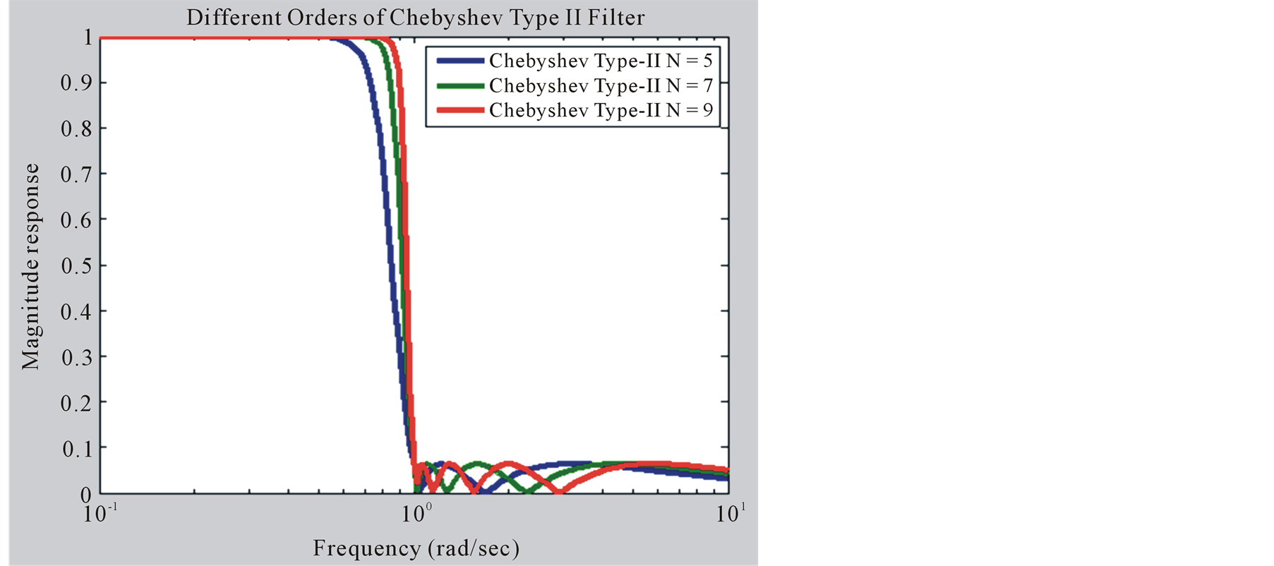
Figure 3. Frequency response of Chebyshev Type-II filter.
4. Elliptic Filter
An Elliptic filter also some times called as Cauer filter, named after Wilhelm Cauer. In Digital Signal Processing its also name as a Zolotarev filter, after Yegor Zolotarev. In this type of filter equi ripple behavior in passband as well as stopband. The amount of ripple of ripple is adjustable in each band. The amount of ripples present in each band shown in Figure 4. Elliptic filter having a property like that if the ripple in the stopband approaches to zero, than it acts as a Chebyshev Type-I filter, if the ripple in the passband approaches to zero, than it acts as Chebyshev Type-II filter, finally the passband and stopband both value approaches to zero, than it acts as a Butterworth filter [6] .
5. Transfer Function of Butterworth Filter
The design of Butterworth Low Pass Filter with the help of passive elements like R, L and C and the magnitude of transfer function is given as under
 (1)
(1)
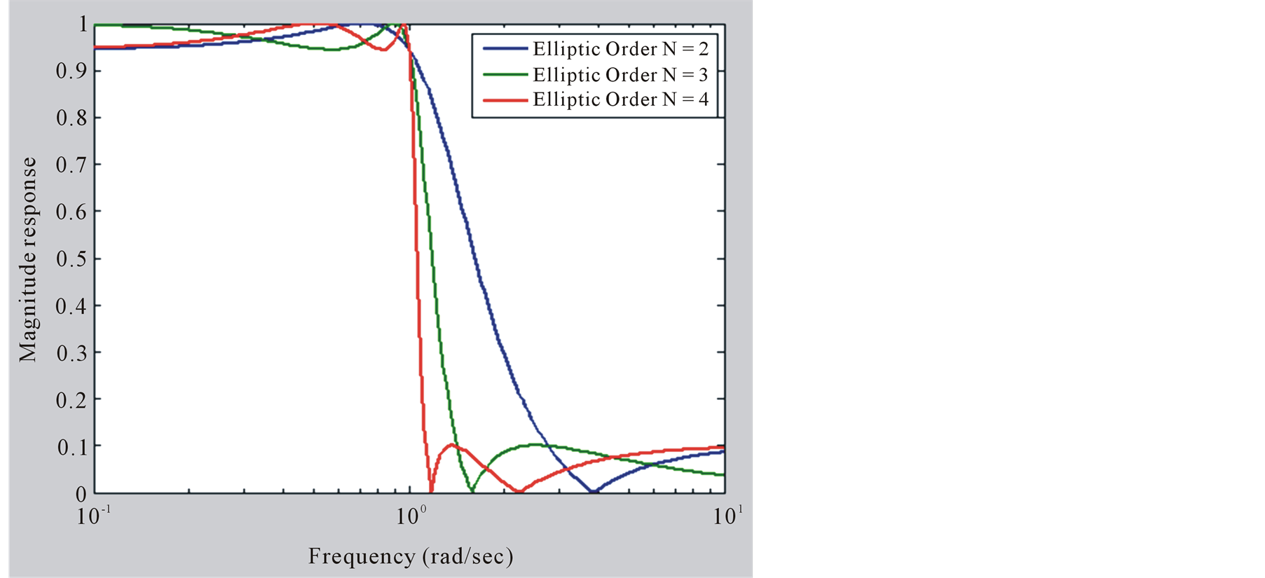
Figure 4. Frequency response of Elliptic filter.
In the above response of filter as increases the value of N, the filter is more closely like a deal brick wall response. To achieve the more accuracy of the filter than increase the order of the filter to get maximum low pass response. The important point is to be noted in Figure 5 are that there are no ripple in the passband as well as stopband as other filters and if we increase the order of N than transition band also decrease as possible.
In Equation (1), N is the order of filter and the subscript “b” denotes the Butterworth
filter,
 is the cutoff frequency of the filter. It is obvious
from Equation (1) that the Butterworth filter is an all Pole filter (i.e. N poles
but not zeros available).
is the cutoff frequency of the filter. It is obvious
from Equation (1) that the Butterworth filter is an all Pole filter (i.e. N poles
but not zeros available).
N = 1…………………………………………………………………………………1st order Butterworth filter N = 2…………………………………………………………………………………2nd order Butterworth filter N = 3…………………………………………………………………………………3rd order Butterworth filter Order means to improve the accuracy of filter, if we require more accuracy we require more order (value of N is high).
Numerator part or 1 is the zero of zeros, because no w value present in numerator, and in denominator part N root means n pole, if N = 1, it has one pole, if N = 3, than filter has a three poles, so due to this Butterworth is also called all pole filter.
The poles of a Butterworth filter can be computed as follows: From Equation (1)

Squaring on both sides

Let


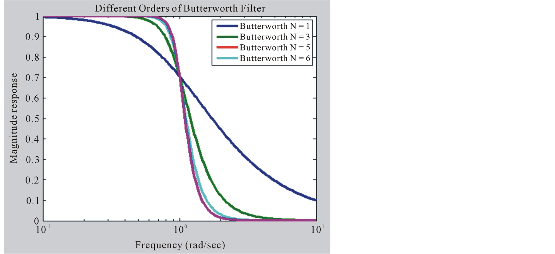
Figure 5. Transfer function of Butterworth filter.

where
 is the stable part and
 is the unstable part of the function put
 to make equation, the quadratic equation is equal to zero


The poles of the filter are the roots of the denominator, i.e.

Taking the value of k is only odd otherwise result is wrong.


Taking square roots on both side


 (2)
(2)

First of all we calculate the first order i.e., N = 1, and the cut-off frequency is 1 radian per second.
Put the value of k = 0 and N = 1 in Equation (2), we get the poles of a first-order Butterworth filter.


So the transfer function of first order Butterworth filter is as under

Now put the value of k = 0, 1 and N = 2 in Equation (2), we get the poles of a second-order Butterworth filter


and

So the transfer functions of second order Butterworth filter are


So similarly in this way we calculate the different Butterworth Polynomials, and
these polynomials are used for designing the Analog Butterworth filter. The Butterworth
up to 6th order standard tables of polynomials are given in Table 1, in which
 radian/sec [7] .
6. Digital Implementation of Butterworth Filter
The Butterworth filter is easily designed from Analog Domain or Laplace Transform to Digital Domain using Z Transform. First of all we calculate the transfer function of Analog Butterworth filter; its transfer function is normally in s-domain and finally applies Impulse Invariance transformation or bilinear transformation, the response of Butterworth in digital form.
7. Similarity of Butterworth with Other Filters
Here is a different signals show the frequency response of Low Pass Filters in Figure 6. The first one is the im

Table 1. Normalized analog Butterworth filter polynomials in factored form.
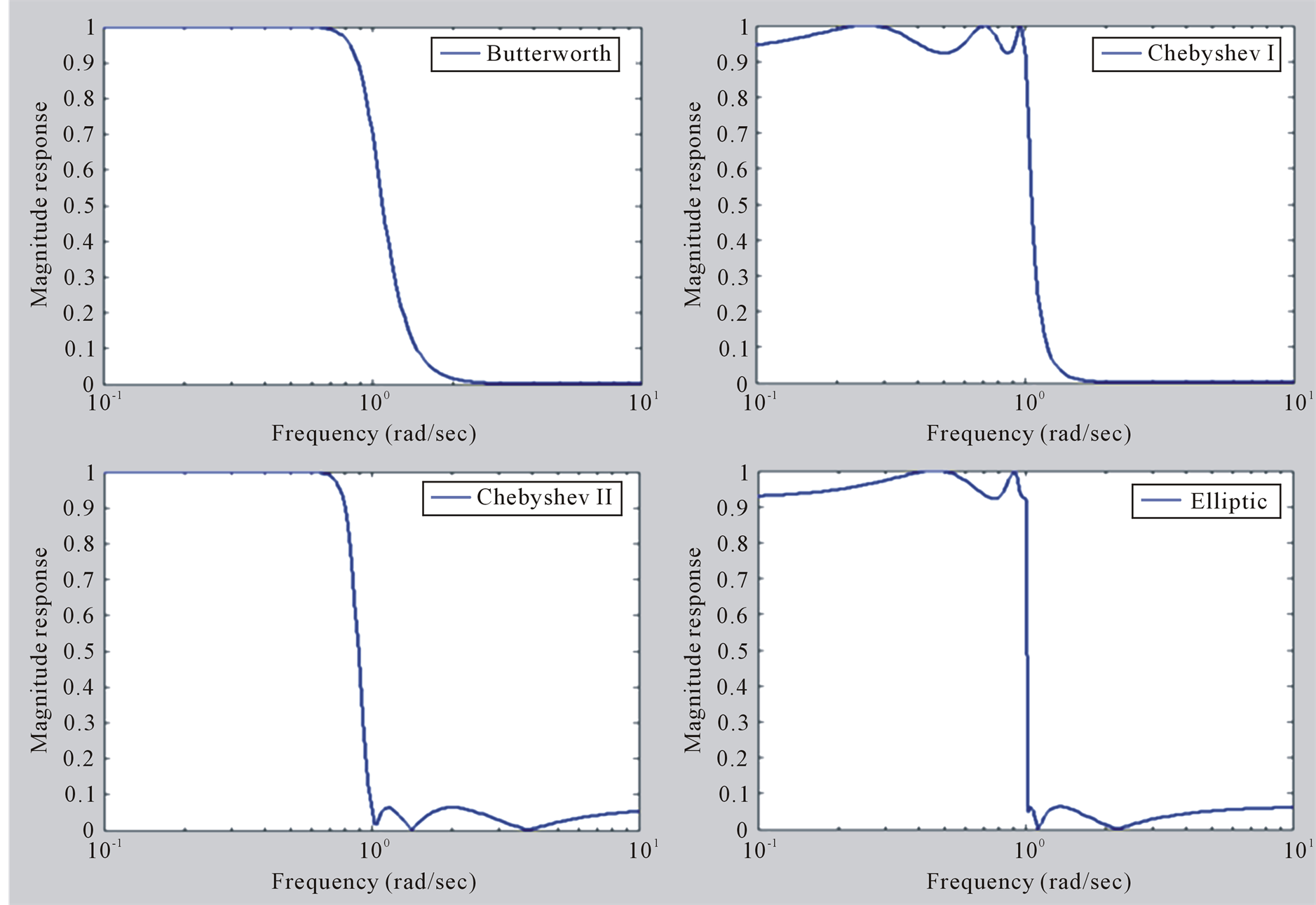
Figure 6. Butterworth comparison with other filters.
age of Butterworth Low Pass Filter that is smooth and no ripples in pass band. In this filter transition time is maximum, if you increase the order of filter its response is like a brick wall shape. The same responses appear in Figure 7. The next is the Chebyshev Type-I filter having no ripples in stopband and some ripples in passband, next is a Type-II Chebyshev Low Pass Filter having no ripples in pass band and some ripples in stop band. Finally the Elliptic filter the ripples are present in both band but transition band of Elliptic filter are minimum than other filters [8] . In Matlab the Filtering function toolbar is available [9] , and also write the Matlab code to draw the different response of the filter.
8. Results
The program for design of Butterworth Low Pass Filter is simulated in MATLAB 7. The output graphs are
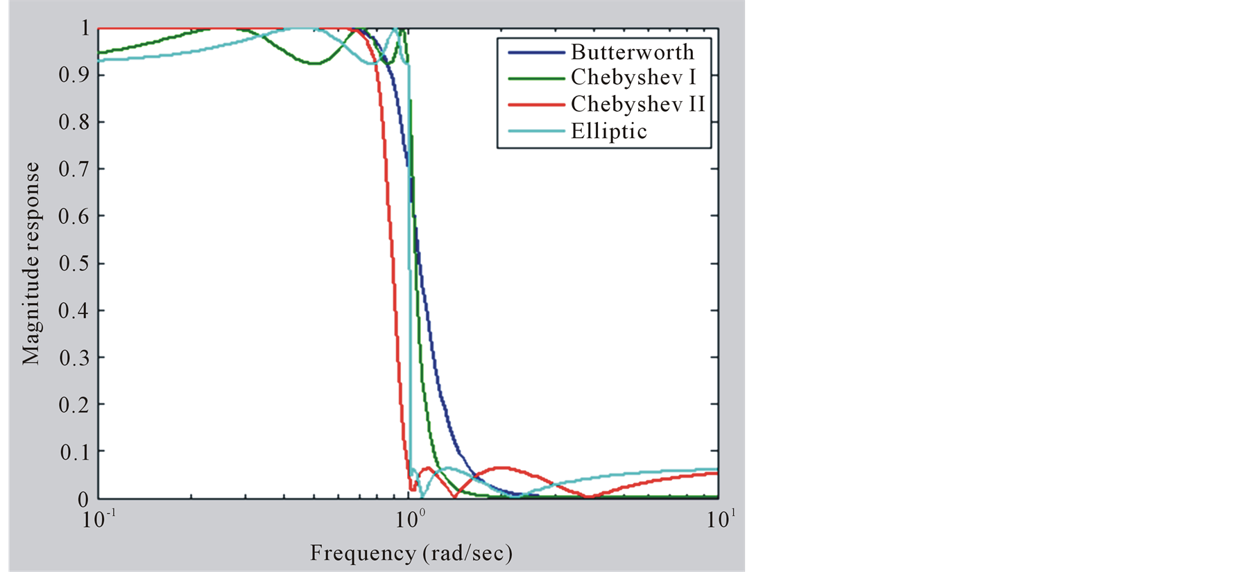
Figure 7. Butterworth comparisons with other filters in MATLAB simulation.
shown in Figure 7, that indicates the Butterworth filter did a better job for removing the low pass-frequency components than the Chebyshev and Elliptic filter [10] . Table 1 gives the results of the coefficients of Low Pass Butterworth filter for order from N from 1 to 6, we calculated.
9. Conclusion and Future Work
In this paper, we described that the low pass Butterworth filter are maximally flat as an amplitude response in the passband, and there is no ripple in passband. The transition time is controlled when you increase the filter order otherwise to obtain the accuracy of filter. The Butterworth response is compared to other filters like Chebyshev-I, Chebyshev-II and Elliptic filters perform better response, and finally draw all filter response in the Matlab 7 for filter response comparisons. Finally, the Butterworth filter comparison is very simple and takes low order for accuracy, but we cannot achieve satisfactory results, so here I suggested other methods or even automatic low filter techniques available to generate different Low Pass Filter responses that adapt to a task.
References
- R.A.Barapate, J.S.Katre (2008) Digital Signal Processing. Second Revised Edition, Tech-Max.
- Williams, A.B. (1981) Electronic Filter Design Handbook. McGraw-Hill, Boston.
- Li, Z.S. (2006) New Study on Butterworth Low Pass Filter. Proceedings of the 1st International Symposium on Test Automation & Instrumentation, 3, 1532-1535.
- Proakis J.G., C.M. Rader, Ling, F.Y., Nikias, C.L., Maoonen, M. and Proudle, L.K. (2002) Algorithm for Statistical Signal Processing. 1st Edition, Pearson Education Inc., Delhi.
- Proakis, J.G. and Manolakis, D.G. (2007) Digital Signal Processing: Principles, Algorithms, and Applications. Pearson Education Ltd., New Jercy.
- Oppenheim, A.V., Schafer, R.W. and Buck J.R. (2003) Discrete-Time Signal Processing. Pearson Education, New Delhi.
- http://www.electronics-tutorials.ws/filter/filter_8.html
- Fernandez-Vazquez, A. and Jovanovic-Dolecek, G. (2006) A New Method for the Design of IIR Filters with Flat Magnitude Response. IEEE Transactions on Circuits and Systems Regular Papers, 53, 1761-1771.
- (1997) MATLAB The Language of Technical Computing. The Math Works Inc., Natick.
- Selesnick, I.W. and Burrus, C.S. (1998) Generalized Digital Butterworth Filter Design. Transactions on Signal Processing, 46, 1688-1694.