Journal of Modern Physics
Vol.4 No.6A(2013), Article ID:33564,4 pages DOI:10.4236/jmp.2013.46A001
Cryogenic System for PKU-FEL
1Technical Institute of Physics and Chemistry, Chinese Academy of Sciences, Beijing, China
2State Key Laboratory of Technologies in Space Cryogenic Propellants, Beijing, China
Email: lyxiong@mail.ipc.ac.cn
Copyright © 2013 Lianyou Xiong et al. This is an open access article distributed under the Creative Commons Attribution License, which permits unrestricted use, distribution, and reproduction in any medium, provided the original work is properly cited.
Received March 18, 2013; revised April 17, 2013; accepted May 14, 2013
Keywords: Free Electron Laser; Superconducting Accelerator; Cryogenic System
ABSTRACT
PKU-FEL based on superconducting (SC) accelerator facility is under construction at Peking University. It will run in IR (5 - 10 μm) and THz (100 - 3000 μm) region as an ideal experimental FEL platform for universities. The SC accelerator facility is composed of a DC-SC injector and a 1.3-GHz 2 × 9-cell SC accelerator. In order to better the performance, the injector and the accelerator are bath-cooled by 2 K super fluid helium in cryostats. A 2 K cryogenic system has been designed, constructed and assembled.
1. Introduction
A free electron laser (FEL) is under construction at Peking University (PKU) since 2007. The goal of PKUFEL is to provide a high average power FEL in IR (5 - 10 μm) and THz (100 - 3000 μm) operation region. In order to generate high-quality electron beams with high average current, an accelerator facility based on superconducting is adopted, which is mainly composed of a DCSC photocathode injector and a superconducting accelerator [1]. PKU-FEL will play an important role as an experimental tool in studying nonlinear transient physical process, chemical kinetics, molecular biology, material science, nuclear physics, high energy physics and so on. The main parameters of PKU-FEL are listed in Table 1 [2].
As both the DC-SC injector and the SC accelerator should be operated at a very low temperature of 2 K, a 2 K cryogenic system is required to supply super fluid helium to cryostats of injector and accelerator.
2. Requirements of PKU-FEL Cryogenic System
The main function of PKU-FEL cryogenic system is to provide 2 K super-fluid helium for bath cooling the superconducting cavities of the accelerator and the DC-SC injector when the facility is in operation. It should also supply 4.2 K liquid helium to keep the superconducting cavities at 4.2 K during the spare time. Thus, the PKUFEL cryogenic system should comprise a liquefier to generate liquid helium at a nominal 4.5 K and a separate 2 K cooling system to generate super fluid helium at 2 K. The process flow diagram of PKU-FEL cryogenic system is given in Figure 1. The helium liquefier consists of a helium compressor, a oil remove system and a vacuum jacked cold box with necessary components installed inside such as heat exchangers, control valves and turbo expander. The 4.5 K liquid helium generated by the helium liquefier is delivered to and stored in a liquid helium dewar. From there the 4.5 K liquid helium is transferred to the 2 K system. The 2 K system is composed of

Table 1. Main parameters of PKU-FEL.
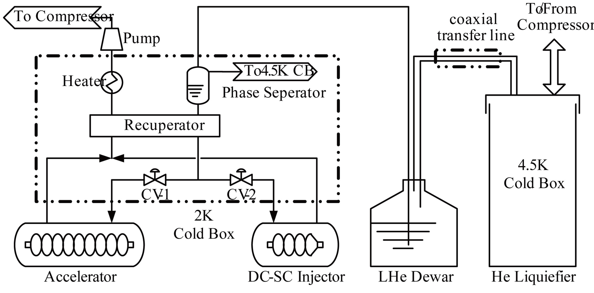
Figure 1. PFD of PKU-FEL cryogenic system.
a vacuum pump unit and a 2 K cold box. Inside the 2 K cold box there are one recuperator, one electrical heater, one phase separator and two JT valves. With the use of vacuum pump and JT valves, 2 K super fluid helium is generated by vacuum evaporating the helium inside the injector and accelerator cryostats under sub-atmospheric pressure. In order to decrease the pumping work of the vacuum pump system, the phase separator and the recuperator are installed at the upstream of the JT valves. During operation the 4.5 K liquid helium from dewar will firstly flow into the phase separator to remove the vapor due to the heat leak along the way. Then it will be subcooled in the recuperator by the 2 K exhaust gas from the superconducting accelerator and injector. Next the subcooled liquid helium will expand across the JT valves to 30 mbar. The 2 K super fluid helium generated after JT valves will transfer to the superconducting injector and accelerator which provide the necessary cooling capacity for the superconducting cavities.
To reduce the total cost and minimize the scale of cryogenic system, PKU-FEL will operate in pulsed mode for 6 - 8 hours each day within 5 days per week and in continuous wave (CW) mode for 2 - 3 hours each day, 2 days per week. As an optimized working plan, the helium liquefier may run at any time when necessary to accumulate liquid helium and then supply the SC facility through the 2 K system during the FEL operation periods of each weekday [3].
Table 2 describes the estimated heat loads for each component in details. The total heat load with 50% contingency at 2 K is 56.1 W for pulsed mode and 210 W for CW mode respectively.
As a result, the required liquefaction capacity of Helium liquefier based on the FEL operation scheme and heat loads should be no less than 93 liters per hour as indicated in Table 3.
When working in pulsed mode, a liquefier with liquefaction capacity of 90 l/hr is capable of serving the PKU-FEL SC facilities. However, as the FEL may also operate in CW mode for 2 - 3 hours each day, the corresponding LHe consumption required is 313 l/hr. For the purpose of working smoothly under CW mode, at least 670 liters LHe should be accumulated within a LHe dewar in advance. A LHe dewar with a capacity of 1000 L or greater is suggested to store the LHe.
Table 4 gives the calculated consumption of 2 K super fluid helium when the PKU-FEL is in operation. In order to keep the SC cavity cryostats under sub-atmospheric pressure, 2.7 g/s helium for pulsed mode and 10.2 g/s helium for CW mode should be evacuated bythe pumping units. Since the super fluid helium consumption dedicated to cooling the transfer lines connecting the 2 K cold box and the SC facilities is unignorable, it’s very important to design and fabricate the 2 K transfer lines with small heat leaks.
3. Construction of PKU-FEL Cryogenic System
Figure 2 presents the layout of the PKU-FEL cryogenic system. The pumping units and the helium liquefier including a helium compressor station, a 4.5 K cold box and a 2000 L LHe dewar are located in cryogenic room, while the 2 K cold box is located in the accelerator hall so as to serve the injector and the accelerator in closer distance.
The liquefier and the 2 K system are made by Linde Kryotechnik AG. The helium liquefier used is L140, whose liquefaction capacity is 110 L/hr with LN precooling and 67 L/hr without LN pre-cooling. Two Leybold vacuum pump units each with a capacity of 1.6 g/s are used to pump the cryostats to less than 30 mbar. Although the total capacity of vacuum pump units adopted in the first stage is only fit for pulsed mode operation, future extension of the pumping system for the requirements of CW mode could be realized by adding 5 identical vacuum pump units.
The cryogenic distribution system, including all the 4.5 K and 2 K cryogenic helium transfer lines, the LN2
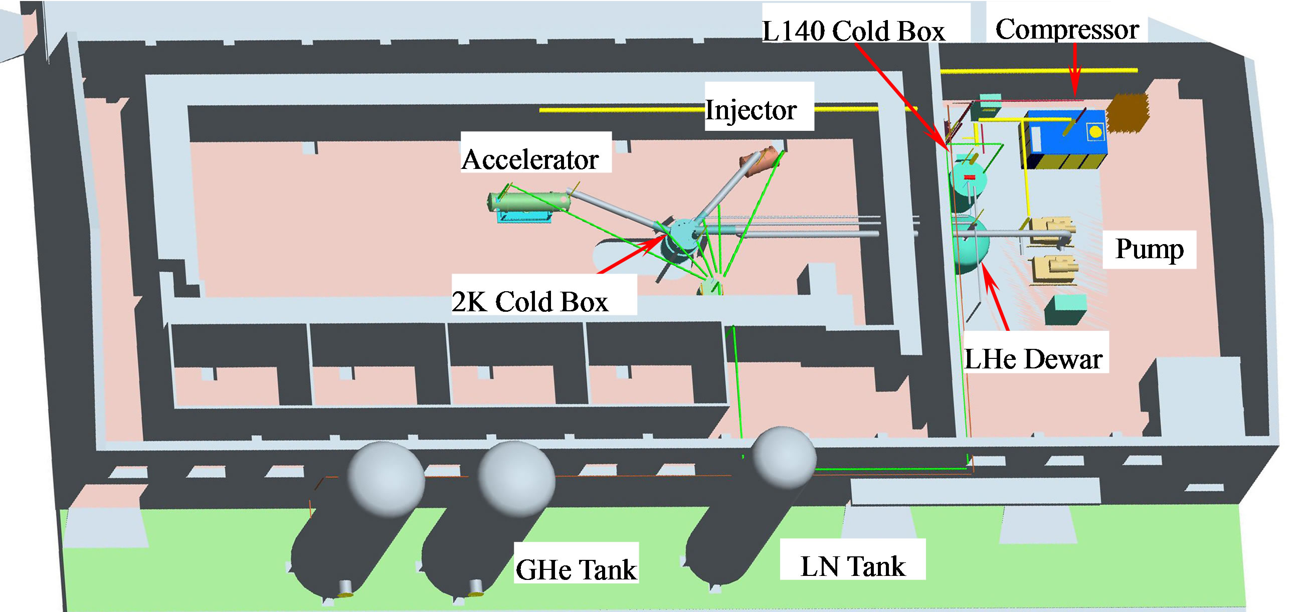
Figure 2. Layout of the PKU-FEL cryogenic system.
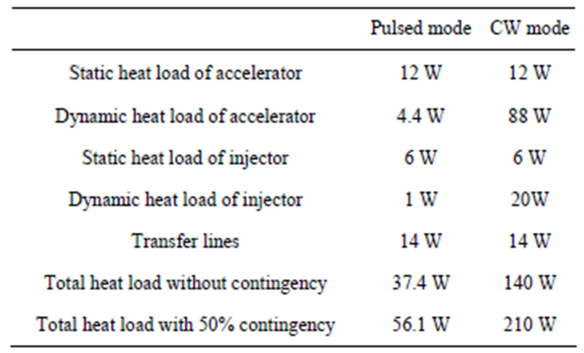
Table 2. Heat load of PKU-FEL cryogenic system at 2 K.
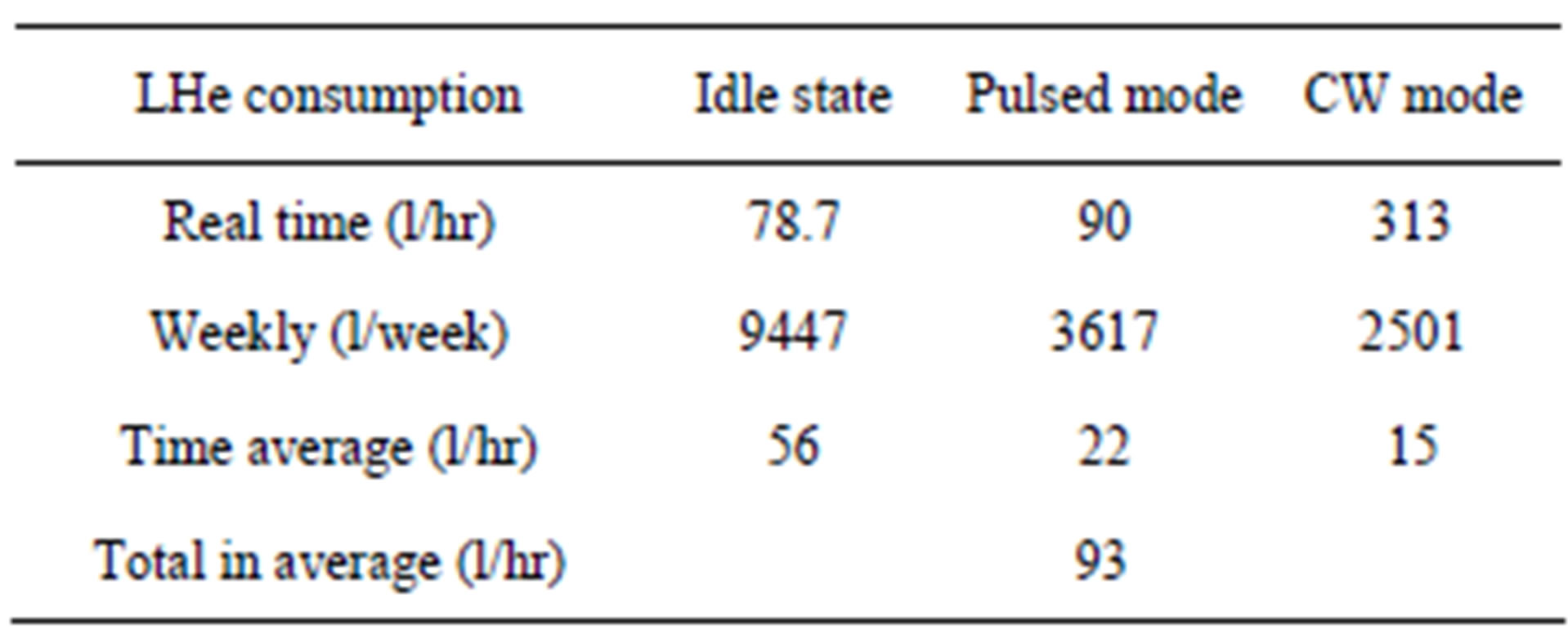
Table 3. LHe consumption of PKU-FEL.
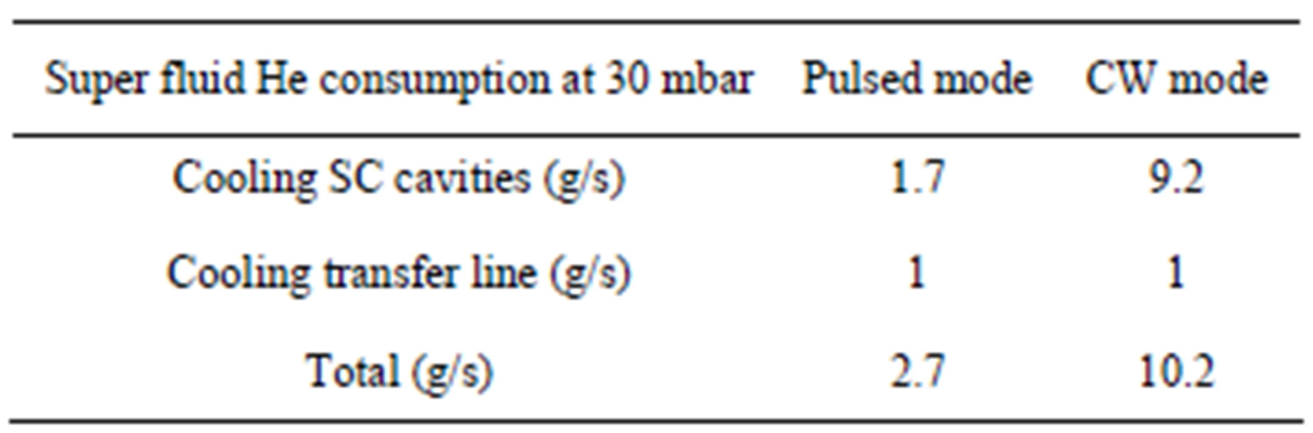
Table 4. Super fluid He consumption of PKU-FEL.
supply lines, GN2 vent lines and the corresponding LN2 control valve box, is designed and made by Technical Institute of Physics and Chemistry.
4. Status of PKU-FEL Cryogenic System
The kick off of the PKU-FEL cryogenic system was started in the middle of 2007. The procurement and on-
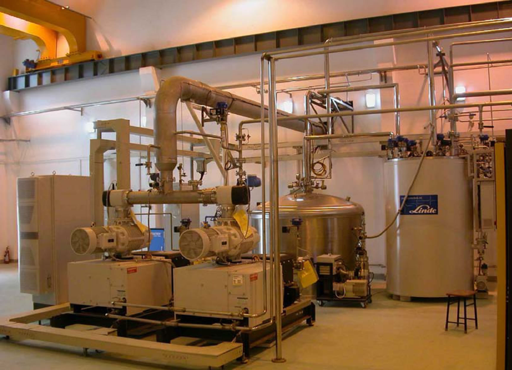
Figure 3. He liquefier and pumping units.
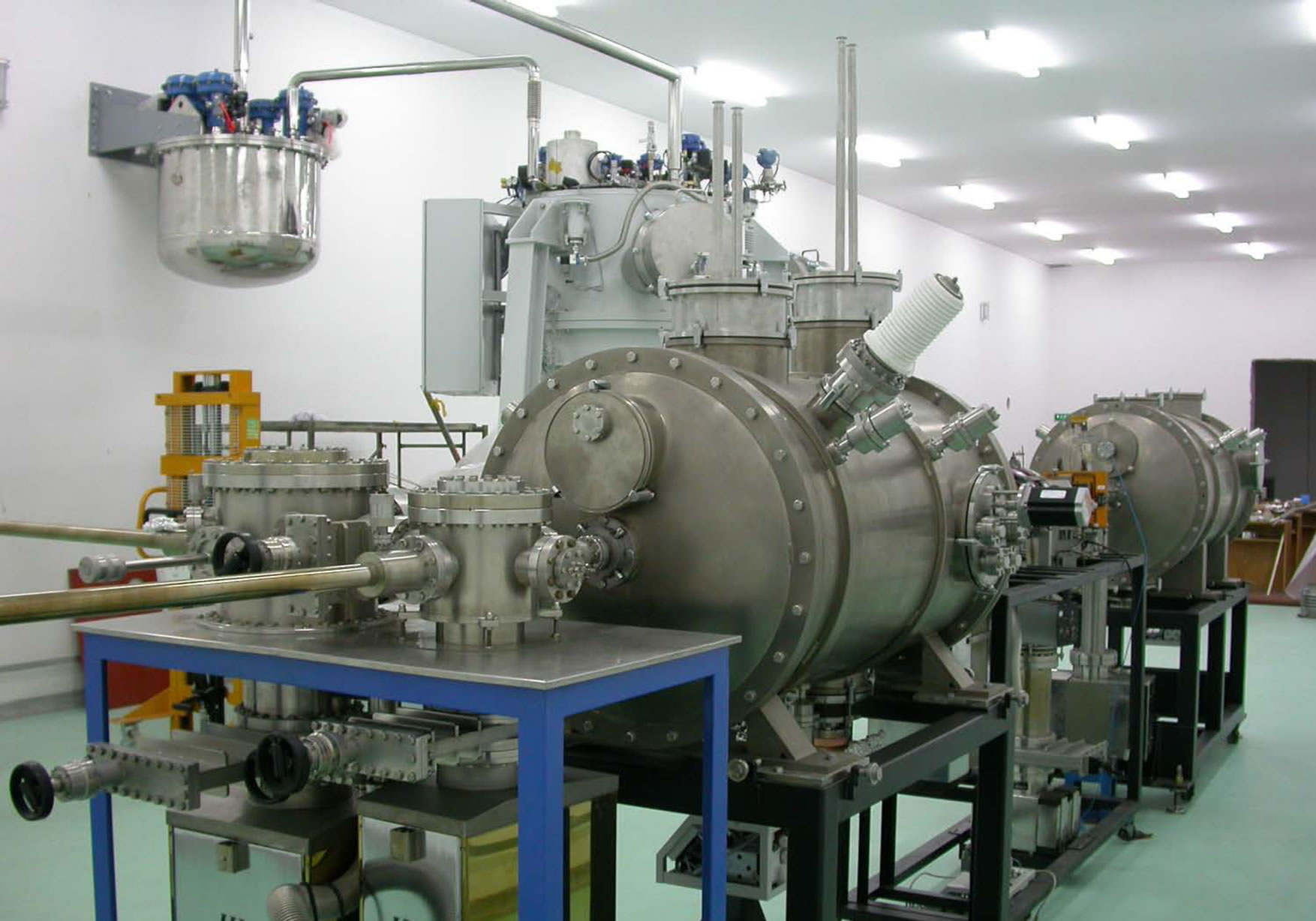
Figure 4. SC facility and 2 K cold box.
site installation of the L140 helium liquefier, 2 K cold box, 2 K pumping units, helium buffer tank and LN2 storage tank was finished in the middle of 2009 as shown in the Figures 3 and 4. The assembly of the LN2 system, cryogenic transfer lines and warm lines were completed at the end of 2009.
As a main milestone, the site commissioning and acceptance test of the cryogenic system with dummy load was successfully carried out between March and May in 2010. According to the acceptance test result, the refrigeration capacity at the outlet of 2 K cold box was 58 W. The pressure fluctuation in the recuperator vessel inside 2 K cold box was less than 0.2 mbar.
The commissioning of the superconducting injector with cryogenic system is performing since the beginning of 2011 [4], while the commissioning of the accelerator will be followed in the nearly future.
5. Summary
The development of cryogenic system for cooling the PKU-FEL facility is finished. This system is the first 2 K level cryogenic system in China which is applied to superconducting accelerator field and is capable of providing 58 W cooling power at 2 K.
REFERENCES
- K. Zhao, S. W. Quan, J. K. Hao, et al., Nuclear Instruments and Methods in Physics Research A, Vol. 483, 2002, pp. 125-128. doi:10.1016/S0168-9002(02)00296-6
- K. Zhao, S. Huang, S. Quan, et al., “Progress of FEL Based on RF Superconducting Accelerator at Peking University,” Proceedings of APAC, Gyeongju, 22-26 March 2004, pp. 25-29.
- J. K. Hao, L. Lin, S. Huang and K. Zhao, Chinese Physics Letters, Vol. 23, 2006, pp. 2674-2677. doi:10.1088/0256-307X/23/10/014
- F. Zhu, S. W. Quan, et al., “Status of the DC-SRF Photoinjector for PKU-SETF,” Proceedings of SRF, Chicago, 25-29 July 2011, pp. 973-976.