Applied Mathematics
Vol.5 No.16(2014), Article ID:49364,9 pages
DOI:10.4236/am.2014.516233
Effects of Layer Thickness and Edge Conditions to Thermoelastic Characteristics on Thermal Barrier Coatings
Jaegwi Go1*, Je-Hyun Lee2
1Department of Mathematics, Changwon National University, Changwon, South Korea
2School of Nano and Advanced Materials Engineering, Changwon National University, Changwon, South Korea
Email: *jggo@changwon.ac.kr, ljh@changwon.ac.kr
Copyright © 2014 by authors and Scientific Research Publishing Inc.
This work is licensed under the Creative Commons Attribution International License (CC BY).
http://creativecommons.org/licenses/by/4.0/


Received 27 June 2014; revised 2 August 2014; accepted 13 August 2014
ABSTRACT
The thermoelastic behaviors of such as temperature distribution, displacements, and stresses in thermal barrier coatings (TBC) are seriously influenced by top coat thickness and edge conditions. The top coat of TBC specimens prepared with TriplexPro™-200 system was controlled by changing the processing parameter and feedstock, showing the various thicknesses and microstructures. A couple of governing partial differential equations were derived based on the thermoelastic theory. Since the governing equations were too involved to solve analytically, a finite volume method was developed to obtain approximations. The thermoelastic behaviors of TBC specimens with the various thicknesses and microstructures were estimated through mathematical approaches with different edge conditions. The results demonstrated that the microstructure and thickness of the top coat, and the edge condition in theoretical analysis were crucial factors to be considered in controlling the thermoelastic characteristics of plasma-sprayed TBCs.
Keywords:Thermal Barrier Coatings, Air Plasma Spray, Layer Thickness, Thermoelastic Characteristics, Finite Volume Method

1. Introduction
Ceramic thermal barrier coating (TBC) technique is a widely used method to improve the durability of metal components. Due to the low thermal conductivity, relatively high thermal expansion, and erosion resistance zirconia-based thermal barrier coatings on metal alloy substrates are preferred in gas turbines in power generation. Recently, widely used techniques for depositing TBCs are the air plasma spraying (APS) and the electron beam physical vapor deposition (EB-PVD) processes [1] -[3] . APS coatings produce a lower thermal conductivity in compared with EB-PVD [4] , while EB-PVD coatings present better corrosion resistance, bond strength, and surface roughness [5] .
The microstructures of the top coat are influenced deeply by the deposition process, the size, shape, and the density of powder. Zotov et al. [6] and Schulz [7] investigated the effects of thermal annealing on the microstructure of TBCs deposited by EB-PVD. The microstructure features of TBCs fabricated through ASP process are clarified by Jung et al. [8] and Lee et al. [9] . Meanwhile, the microstructural feature yields crucial effects on the thermal and mechanical properties in TBC systems. Especially, the thermal conductivity is so sensitive to the variation of various parameters such as the physical size of an object, grain size, coating thickness and the space of splat boundary depending on temperature. Kwon et al. [10] investigated mechanical characterization and contact damage of zirconia-based TBC systems with different bond coat thickness using nanoindentation and Hertzian tests, and spallation mechanism in TBC with graded bond costs analyzed by Pindera [11] . Moreover, Sarikaya and Celik [12] studied the effects of residual stress on thickness and interlayer of TBCs. However, the effects of top coat thickness to the thermoelastic characteristics are not sufficiently announced.
In the present paper, the effects of top coat thickness to the thermoelastic characteristics of TBC circular specimens are analyzed considering different boundary conditions. TBC specimens were prepared by TriplexPro™-200 system using different commercialized powders for the bond and top coats. The top coat with about 0.6 mm thickness was prepared with METCO 204 NS and the bond coat with about 0.3 mm thickness was prepared with AMDRY 962. For temperature distribution profiles heat flux is applied at each layer. Based on the thermal elastic theory, a couple of partial differential equations are derived and a finite volume approach is adopted to analyze the thermoelastic characteristics. The results and the analysis performed may contribute further understanding to the thermoelastic behaviors of TBCs.
2. Mathematical Modelling
2.1. Temperature Distribution Formulation
According to the assumption that the circular sample is subjecting to a uniform
temperature loading to the longitudinal
 -direction (see Figure 1),
the differential equation for is
-direction (see Figure 1),
the differential equation for is
 (1)
(1)
The general solution of Equation (1) is
 (2)
(2)
where
 and
and
 are integral constants. The boundary conditions for integral constants are given
by
are integral constants. The boundary conditions for integral constants are given
by
 (3)
(3)
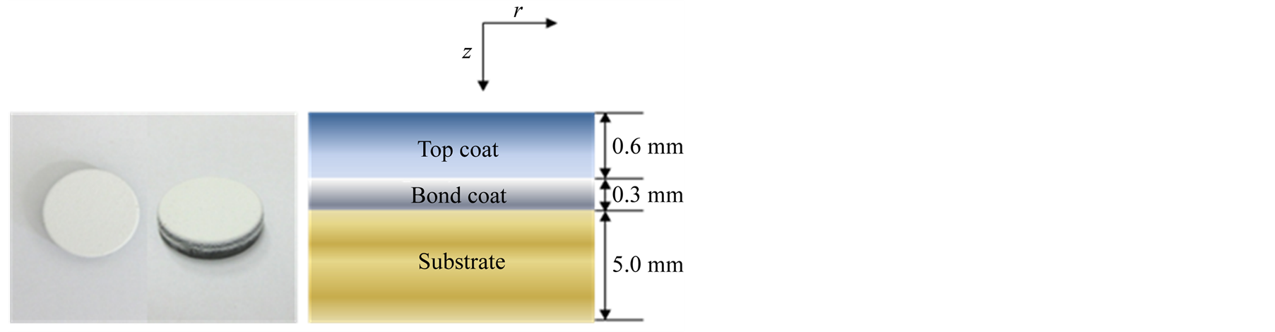
Figure 1. A circular disk model for thermoelastic characteristics of TBCs.
But, only two boundary contions
 and
and
 are provide and additional necessary information is required to obtain the unique
temperature distribution profile for each layer. Heat flux point takes into account
at each layer, and the equations for
are provide and additional necessary information is required to obtain the unique
temperature distribution profile for each layer. Heat flux point takes into account
at each layer, and the equations for
 layer are expressed as
 (4)
(4)
where
 is the heat flux into
 layer,
![]() the condcutivity, and
the condcutivity, and
 the length of
 layer. Then, the integral constants for the temperature distribution profile at
each
layer. Then, the integral constants for the temperature distribution profile at
each
 layer in the cyclinder model can be determined uniquely by solving the following
linear system:
layer in the cyclinder model can be determined uniquely by solving the following
linear system:
 (5)
(5)
For the cylinder model consisting of n layers, since the
 is known value solved by
 layer linear system and Tout is given initial value, the number of
 equations will determine
 ’s unknown coefficients.
When
’s unknown coefficients.
When , only two unkown integral coefficients
 and
and
 with two equations will be determined easily. Similar process can apply to the temperature
distribution profile of the circular disk.
with two equations will be determined easily. Similar process can apply to the temperature
distribution profile of the circular disk.
2.2. Thermoelastic Formulation
Since the temperature profiles pressures the circular disk to the longitudinal direction
only, all quantities are independent of circumferential
 direction. Equilibrium equations in polar coordinates thus are
 (6)
(6)
Let
![]() be the displacement to the radial direction, let
be the displacement to the radial direction, let
![]() be the displacement to the circumferential direction, and let
be the displacement to the circumferential direction, and let
![]() be the displacement to the longitudinal direction. The independence of all quantities
in circumferential direction yields the following strain-displacement relations
be the displacement to the longitudinal direction. The independence of all quantities
in circumferential direction yields the following strain-displacement relations
 (7)
(7)
The strain-stress relations due to the thermal expansion can be expressed as
 (8)
(8)
where

The combination of Equations (6)-(8) leads to the following governing equations
 (9a)
(9a)
 (9b)
(9b)
where
 and
and .
.
2.3. Finite Volume Formulation
The governing Equations (9) for the circular disk are too complicate to be solved
analytically and a finite volume method is adopted to obtain approximated solutions.
The domain is divided up into control volume and integrates the field equations
over each control volume. The finite surface mesh is denoted by
 and the discretisations for the governing equations are developed based on the following
relations at the adjacent locations;
and the discretisations for the governing equations are developed based on the following
relations at the adjacent locations;

In the equations a subscript
![]() implies the value of the displacement at the boundary of the control surface.
implies the value of the displacement at the boundary of the control surface.
According to above relations at the adjacent locations the governing equations (9) are discretised as below


The numerical solutions presenting the thermoelastic behaviors are obtained based on the following boundary conditions:
i)

ii) .
.
3. Results and Discussion
The samples are controlled by the variation of the top coat thickness: 0.3, 0.6, 0.9, and 1.2 mm, and the bond coat and the substrate remain unchanged. Figure 2 displays the temperature distribution profiles according to the mechanical and thermal properties shown in Table1
Variable z (mm)
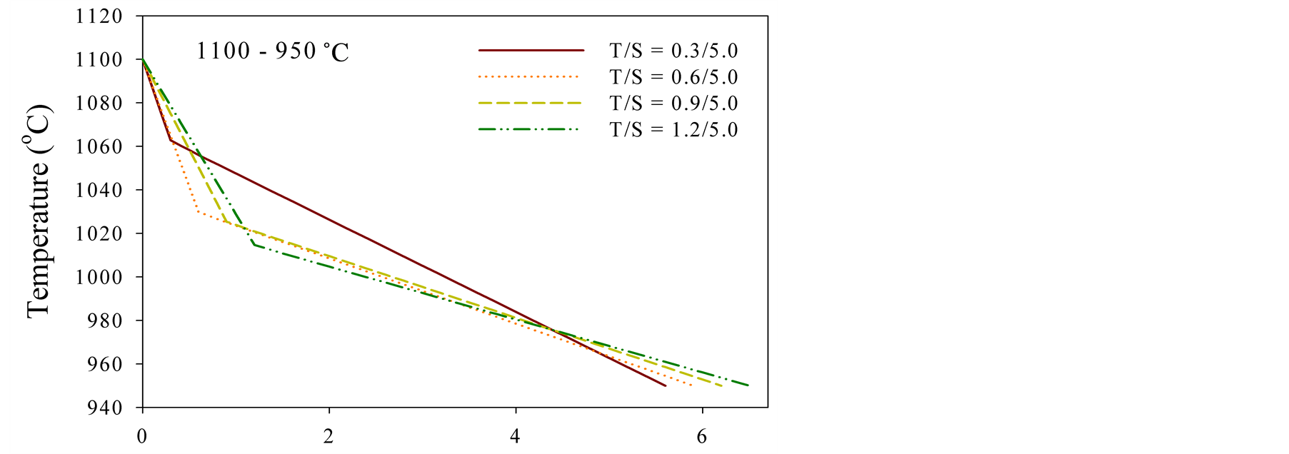
Figure 2.Temperature distribution profiles of TBC samples.

Table 1. Mechanical and thermal properties used in this study for analyzing thermoelastic characteristics.
The samples manufactured with METECO 204 NS features a low thermal conductivity at the top coat, whose property is depicted by the largest decline of the temperature distribution profiles at the top coat. As the thickness of the top coat increases the bond coat and the substrate are under the influence of lower temperature. The rate of temperature decrease is getting slower due to the increase of metal concentration to the longitudinal direction, demonstrating that the mathematical approach is reliable and reasonable.
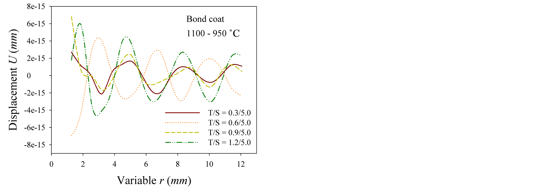
Figure 3 shows the radial displacement distribution profiles at the bond coat. Figure 3(a) represents the radial displacement at the bond coat of samples with fixed edges and Figure 3(b) the radial displacement at the bond of samples with moving edges, respectively.
The radial displacements of TBC models undulate along the radius and the magnitude of fluctuation is getting larger as the thickness of the top coat increases, in the samples with fixed boundaries (see Figure 3(a)). However, opposite inclination is appeared in the samples with moving boundaries. The sample with top thickness 0.3 mm exhibits the largest magnitude and decreases the thickness of the top coat increases (see Figure 3(b)).
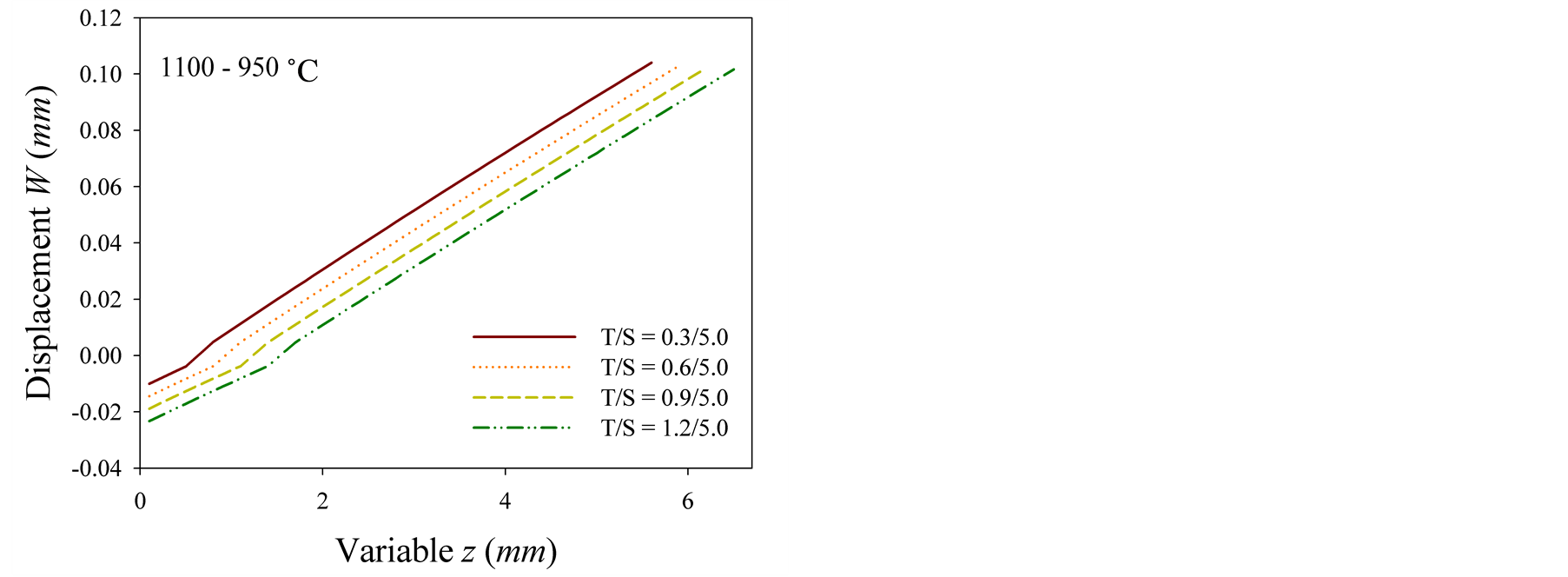
The longitudinal displacement distribution profiles are presented in Figure 4. The extension to the longitudinal direction is larger according to the decrease of the top coat thickness at the samples with fixed edges, which is due to the loading of higher temperature (see Figure 4(a)).
For the samples with moving boundaries the longitudinal extension is displayed near the center and edge of the domain. Unlike the samples with fixed edge, the displacement fluctuates along the longitudinal direction both near the center and edge. Almost all over the domain, the extension appears to the positive direction near the center, while the displacement near the edge develops to the negative direction (see Figure 4(b) and Figure 4(c)). Moreover, the extension of the substrate is getting larger near the edge as the radial thickness decreases.
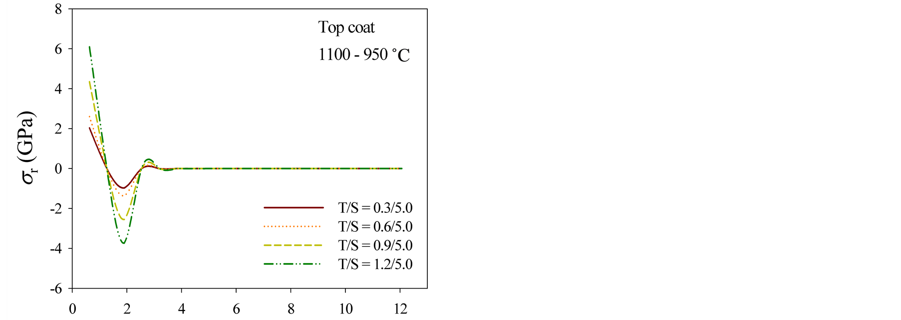
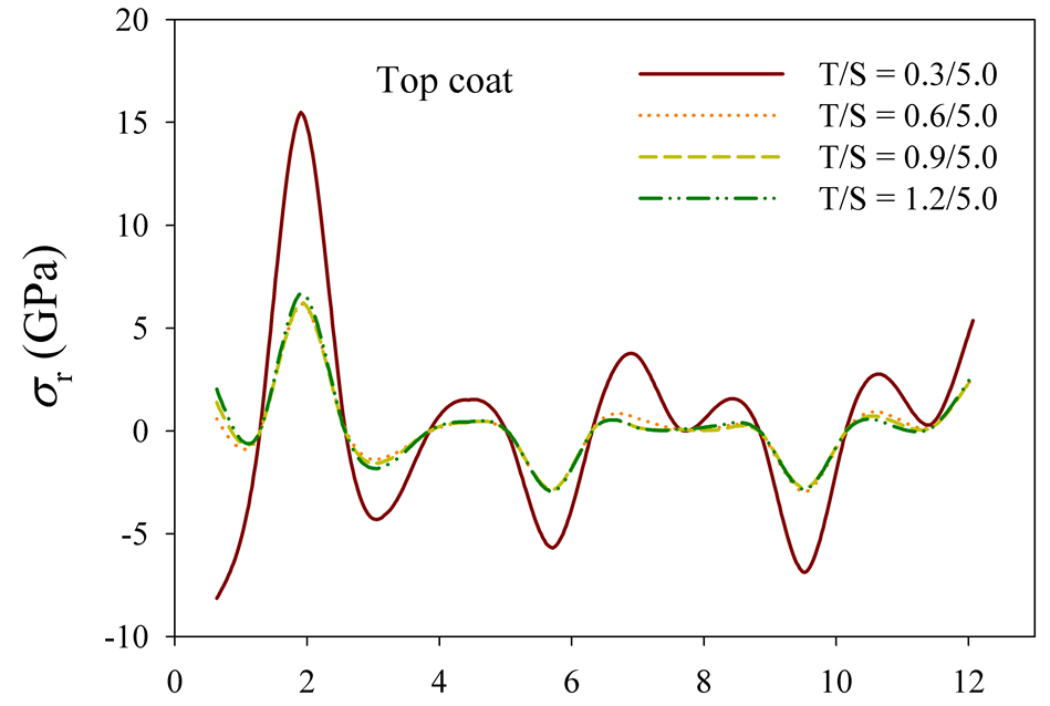
Figure 5 exhibits the radial stress distribution profiles at the top coat. For the samples with fixed boundaries the largest top thickness produces the largest tensile at the center and the difference of the radial stress distribution is trivial most of area of the substrate (Figure 5(a)). However, the smallest top thickness creates a fluctuation showing the largest magnitude along the radius in the samples with moving edges (see Figure 5(b)). The center of the sample having the smallest top thickness is under the loading of the largest compressive and tensile at the center and edge, respectively. The radial stress movements of the other samples carrying moving boundaries are similar.
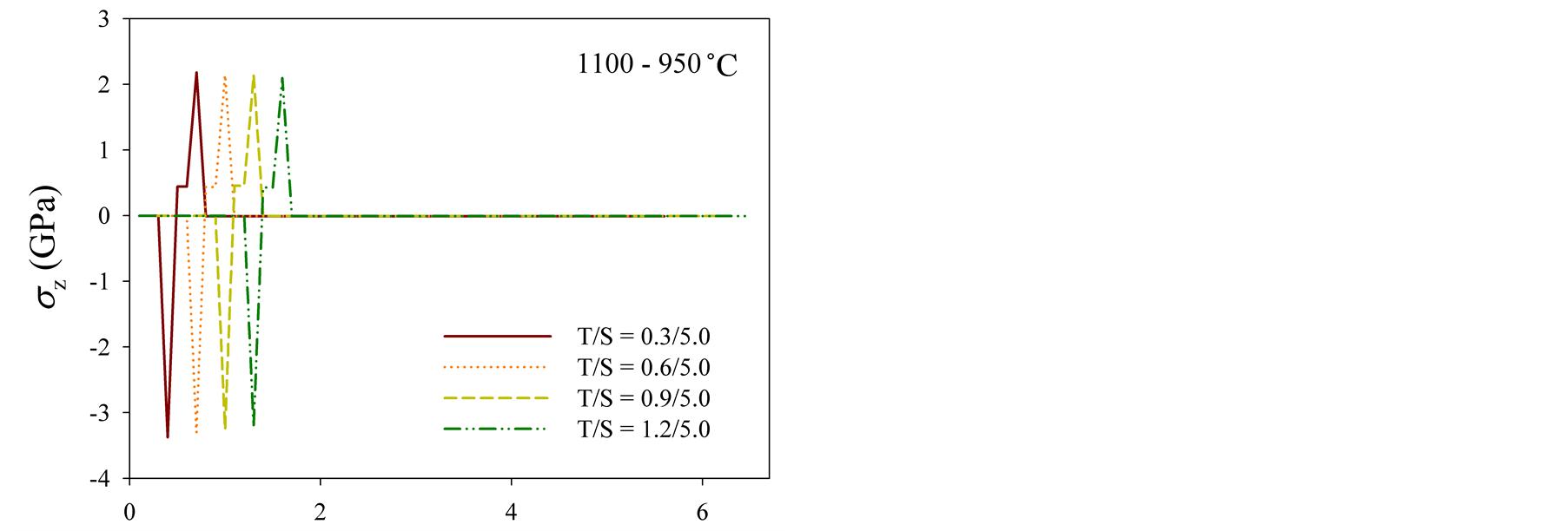
The longitudinal stress distribution profiles are displayed in Figure 6. The stress intensity at the both interfaces between the top and bond coats, and the bond coat and the substrate decreases according to the increase of
 (a)
(a) (b)
(b)
Figure 3. Radial displacement generated at bond coat: (a) fixed boundary and (b) moving boundary.
 (a)
(a)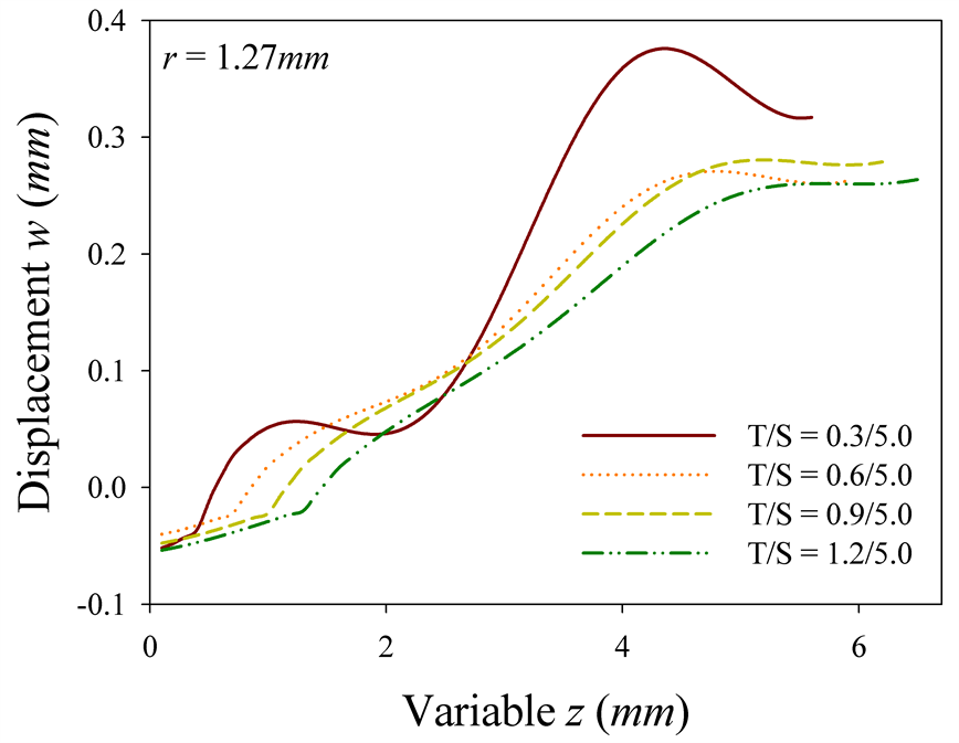 (b)
(b) (c)
(c)
Figure 4. Longitudinal displacement: (a) fixed boundary, and (b) moving boundary at r = 1.27 mm and (c) r = 11.43 mm.
top thickness in the edge-fixed models, implying lower influence of the temperature (see Figure 6(a)). For the samples with moving boundaries the both interfaces show only tensile stress near the center and the intensity is getting smaller as the top thickness increases (see Figure 6(b)). Near the boundary, the interface between the top and the bond coats is under the compressive stress, whereas the tensile develops at the interface between the bond coat and the substrate (see Figure 6(c)). The stress intensity at the both interfaces decreases as the top thickness increases. In addition, the longitudinal stress, unlike the edge-fixed models, generates a fluctuation at the substrate, which is an influence of the release of boundary constraints.
Variable r (mm) Variable r (mm)
 (a)
(a)
 (b)
(b)
Figure 5.Radial stress distribution profiles at the top coat: (a) fixed boundary and (b) moving boundary.
 (a)
(a)
 (b)Variable r (mm) Variable r (mm)
 (c) Variable z (mm)
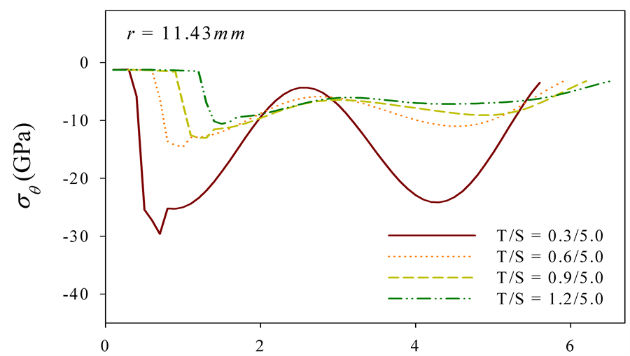
Figure 6.Longitudinal stress distribution profiles: (a) fixed boundary, and (b) moving boundary at r = 1.27 mm and (c) r = 11.43 mm.
Figure 7 represents the circumferential stress distribution profiles. As shown in Figure 7(a), the models with fixed boundaries are under the loading of compressive over the entire domain and the largest compressive stress occurs near the center. As the top thickness increases the intensity of compressive stress decreases near the center and trivial distinction appears over the domain except center part. Meanwhile the samples with moving edges fluctuate in developing of circumferential stress over the entire domain and the magnitude of fluctuation is get-
 (a)
(a)
 (b)Variable r (mm) Variable r (mm)
 (c) Variable z (mm)
Figure 7.Circumferential stress distribution profiles: (a) fixed boundary, and (b) moving boundary at r = 1.27 mm and (c) r = 11.43 mm.
ting smaller as the top coat is thicker (see Figure 7(b) and Figure 7(c)). The entire domain is influenced by a compressive loading near the edge and the largest compressive stress happens on the sample having the largest top thickness, while the tensile stress develops most of area near the center and the sample of the largest top thickness generates the largest tensile.
4. Conclusion
The thermoelastic characteristics have been investigated for various TBC models. Thicker top coat, as shown in the temperature distribution profiles, causes more reducing of high temperature at the top coat, which yields lower temperature influence on the bond coat and the substrate. As the thickness of the top coat increases, in the radial displacement distribution profiles, the magnitude of fluctuation is getting larger in the samples with fixed boundaries. But, thicker top coat displays smaller magnitude in the samples carrying moving boundaries. The samples with fixed edges extend to the positive longitudinal direction only and larger displacement is developed according to the decrease of the top coat thickness, implying higher temperature loading. But, the extensions of the samples with moving boundaries appear to the positive direction near the center and to the negative direction near the edge, describing an influence of the release of fixed edge constraints. The thicker top coat produces larger radial tensile stress at the center in the samples with fixed edges and the fluctuation of the smallest magnitude for radial stress in samples carrying moving boundaries. In the longitudinal stress distribution profiles the stress intensity at the both interfaces decreases as the top thickness increases. Throughout mathematical approach it demonstrates that the thermal stability of TBC and wear resistance of the surface can be improved by controlling the microstructure and thickness of the top coat.
Acknowledgements
This research was supported by Basic Science Research Program through the National Research Foundation of Korea (NRF) funded by the Ministry of Education (2013R1A1A2059235).
This work was supported by the National Research Foundation of Korea (NRF) grant funded by the Korea government (MSIP) (2011-0030058).
References
- Clarke, D.R. and Levi, C.G. (2003) Materials Design for the Next Generation Thermal Barrier Coatings. Annual Review of Materials Research, 33, 383-417. http://dx.doi.org/10.1146/annurev.matsci.33.011403.113718
- Wolfe, D.E., Singh, J., Miller, R.A., Eldridge, J.I. and Zhu, D.M. (2005) Tailored Microstructure of EB-PVD 8YSZ Thermal Barrier Coatings with Low Thermal Conductivity and High Thermal Reflectivity for Turbine Applications. Surface and Coatings Technology, 190, 132-149. http://dx.doi.org/10.1016/j.surfcoat.2004.04.071
- Guo, S. and Kagawa, Y. (2006) Effect of Thermal Exposure on Hardness and Young’s Modulus of EB-PVD Yttria-Partially-Stabilized Zirconia Thermal Barrier Coatings. Ceramics International, 32, 263-270. http://dx.doi.org/10.1016/j.ceramint.2005.01.018
- Itoh, Y., Saitoh, M. and Tamura, M. (2000) Characteristics of MCrAlY Coatings Sprayed by High Velocity Oxygen-Fuel Spraying System. Journal of Engineering for Gas Turbines and Power, 122, 43-49. http://dx.doi.org/10.1115/1.483173
- Wu, Y.N., Zhang, G., Feng, Z.C., Zhang, B.C., Liang, Y. and Liu, F.J. (2001) Oxidation Behavior of Laser Remelted Plasma Sprayed Coatings, NiCrAlY and NiCrAlY-Al2O3. Surface and Coatings Technology, 138, 56-60. http://dx.doi.org/10.1016/S0257-8972(00)01102-6
- Zotov, N., Bartsch, M., Chernova, L., Schmidt, D.A., Havenith, M. and Eggeler, G. (2010) Effects of Annealing on the Microstructure and the Mechanical Properties of EB-PVD Thermal Barrier Coatings. Surface and Coatings Technology, 15, 452-464. http://dx.doi.org/10.1016/j.surfcoat.2010.07.008
- Schulz, U. and Schmücker, M. (2000) Microstructure of ZrO2 Thermal Barrier Coatings Applied by EB-PVD. Materials Science and Engineering: A, 276, 1-8. http://dx.doi.org/10.1016/S0921-5093(99)00576-6
- Jung, S.-I., Kim, J.-H., Lee, J.-H., Jung, Y.-G., Paik, U. and Lee, K.-S. (2009) Microstructure and Mechanical Properties of Zirconia-Based Thermal Barrier Coatings with Starting Powder Morphology. Surface and Coatings Technology, 204, 802-806. http://dx.doi.org/10.1016/j.surfcoat.2009.09.070
- Lee, J.-H., Tsai, P.-C. and Chang, C.-L. (2008) Micro-structure and Thermal Cyclic Performance of Laser-Glazed Plasma-Sprayed Ceria-Yttria-Stabilized Zirconia Thermal Barrier Coatings. Surface and Coatings Technology, 202, 5607-5612. http://dx.doi.org/10.1016/j.surfcoat.2008.06.118
- Kwon, J.Y., Lee, J.H., Jung, Y.G. and Paik, U. (2006) Effect of Bond Coat Nature and Thickness on Mechanical Characteristic and Contact Damage of Zirconia-Based Thermal Barrier Coatings. Surface and Coatings Technology, 201, 3483-3490. http://dx.doi.org/10.1016/j.surfcoat.2006.07.240
- Pindera, M.-J., Aboudi, J. and Arnold, S.M. (2002) Analysis of Spallation Mechanism in Thermal Barrier Coatings with Graded Bond Coats Using the Higher-Order Theory for FGMs. Engineering Fracture Mechanics, 69, 1587-1606. http://dx.doi.org/10.1016/S0013-7944(02)00048-6
- Sarikaya, O. and Celik, E. (2002) Effects of Residual Stress on Thickness and Interlayer of Thermal Barrier Ceramic MgO-ZrO2 Coatings on Ni and AlSi Substrates Using Finite Element Method. Material and Design, 23, 645-650. http://dx.doi.org/10.1016/S0261-3069(02)00047-X
NOTES

*Corresponding author.