Modern Instrumentation
Vol.2 No.2(2013), Article ID:30805,5 pages DOI:10.4236/mi.2013.22004
The Method Exploration for Measuring the Strain of the Intervertebral Disc
1Department of Precision Instrument and Mechanology, Tsinghua University, Beijing, China
2Research Institute of Tsinghua University in Shenzhen, Shenzhen, China
Email: xueqh08@mails.tsinghua.edu.cn
Copyright © 2013 Qinghua Xue et al. This is an open access article distributed under the Creative Commons Attribution License, which permits unrestricted use, distribution, and reproduction in any medium, provided the original work is properly cited.
Received February 17, 2013; revised March 20, 2013; accepted April 1, 2013
Keywords: Cylindroid Hypothesis; Intervertebral Strain; Degeneration
ABSTRACT
Many researches point out that intervertebral pressure and transformation are key parameters for evaluating intervertebral disc degeneration. Aiming at avoiding the damage caused by direct and indirect measuring methods, this research proposes a cylindroid hypothesis and measuring method, which can monitor the strain condition of the intervertebral disc in vivo and real-time without being damaged.
1. Introduction
According to incomplete statistical analysis, around 7% - 10% of the 1.3 billion people in China have some kind of cervical disease. It shows a growing trend. After some kind of treatment, the motion function of the fused segments is lost forever and the adjacent level becomes degenerate easily [1]. Both biochemical and mechanical factors are thought to deal with the cascade of events caused by degeneration [2,3]. Many researches have pointed out that intervertebral pressure and transformation were the key parameters for evaluating degeneration. Monitoring the intervertebral strain in vivo was very important for evaluating the long-term result of surgery and checking the degeneration of the adjacent levels [4,5]. Many analytic or geometric and finite element models have been developed to describe the structural response of intervertebral discs [6]. At present, direct measurement can’t be done nondestructively [7], indirect measurement and simulation can’t reach an agreement [8-10].
Based on the physiology structure and properties of the intervertebral disc, this study raised a solution that could monitor the intervertebral strain in vivo without being damaged. It can solve the intervertebral disc strain measure dilemma that direct measure methods can only be executed on a few healthy volunteers and other simulation or indirect measures are too hard to achieve an agreement.
Aiming at getting the strain condition of the intervertebral disc, a mathematic model and a measurement system based on strain gauges was built. In our hypothesis, the complete strain condition and the dimension of the disc can be calculated by only fixing 6 strain gauges on the front side of an intervertebral disc.
2. Description of the Intervertebral Disc Strain Measurement Model
2.1. Definition of Initial Condition
In some imaging measurement about intervertebral disc, we can easily find out that the transverse section of the disc is an axialsymmetrypolygonwith a smooth border. At first, the study assumes the geometric shape of the intervertebral disc as a cylindroid, sets the origin at the geometric center and establishes a coordinate in the vertical view. As Figure 1 shown, the right side is set as the X axis, the front side is set as the Y axis, and the top side is set as the Z axis.
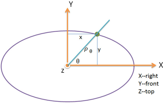
Figure 1. Coordinate built on the intervertebral disc.
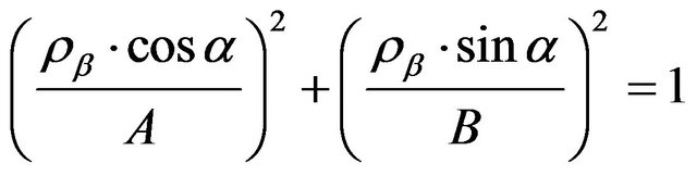
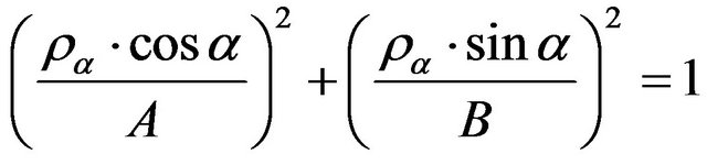
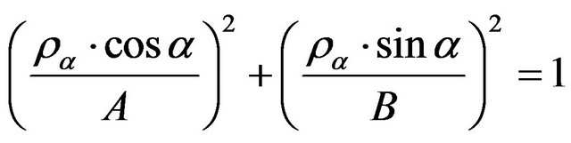
According to the result of actual measurement, the length in the coronal plane is longer than the length in the sagittal plane, the expression of the side face of the disc in Cartesian coordinates is:
 (1)
(1)
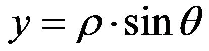
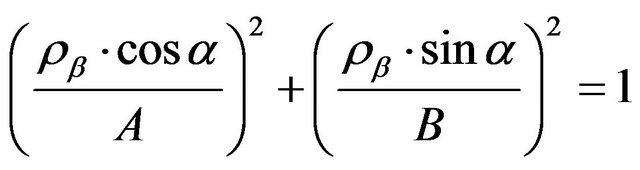
A is the long axis of the ellipse, B is the short axis of the ellipse, and A > B. As the dimension of the ellipse can’t be measured in vivo, A and B are both unknown. With the help of the transfer equation between Cartesian coordinates and polar coordinates:
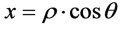 (2)
(2)
 (3)
(3)
We can rewrite (1) as:
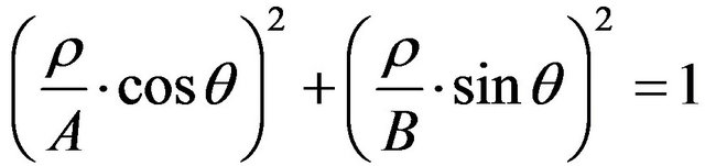 (4)
(4)
Link a certain point on the ellipse’s angle with the origin, the angle between the X axis and it is ,
,  is the distance between from the point to the origin. Any point on the ellipse can be described as
 .
.
2.2. Equation of Geometric Condition
In order to realize the nondestructive measurement, only a bit of arc symmetric with Y axis is available.
As Figures 2 and 3 show, 6 strain gauges were packaged in flexible PCB and fixed on the front surface of the intervertebral disc, symmetrical with YZ plane. ab = de and bc = cd.
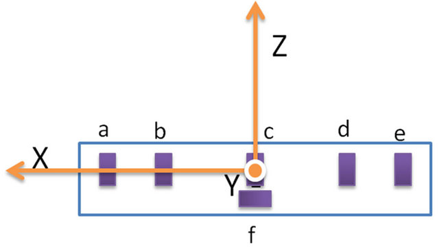
Figure 2. Front view of the strain gauges’ location.
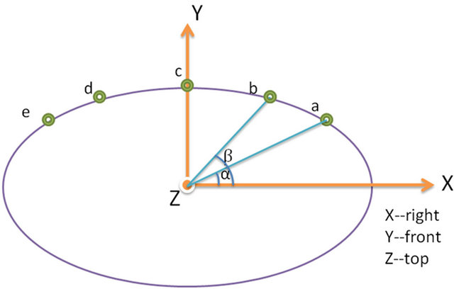
Figure 3. Top view of the strain gauges’ location.
a, b, c, d, e are tensile strain gauges and sensitive for the tension in Z direction. f is a shear strain gauge and sensitive for the in torsion Z direction. The measuring result of f is independent to others’ equation, we focus on the geometric equation and strain equation of a, b, c, d, e.
After fixing the flexible PCB right in the front of the intervertebral disc, there are only 4 independent parameters: 
The location of a, b, c, d, e are respective: ,
,
 ,
,  ,
, ,
, .
.
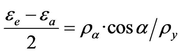
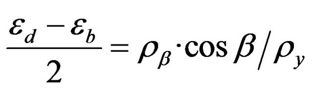
We can get 2 independent equations:
 (5)
(5)
 (6)
(6)
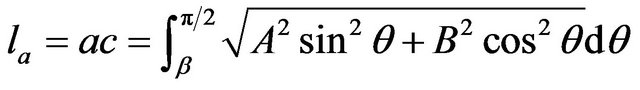
Add the arc length formula of plane curve:
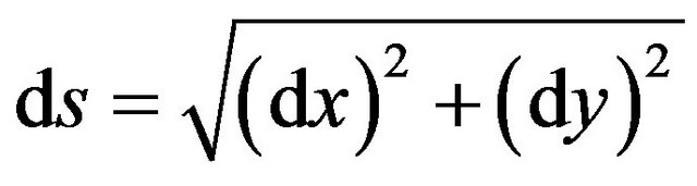 (7)
(7)
We can get:
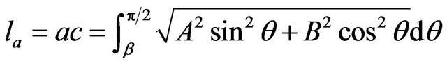 (8)
(8)
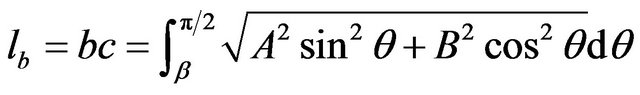 (9)
(9)
In the equation above:  and
and  are known quantity,
 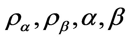 are unknown quantity.
2.3. Equation of Physical Condition
In the normal stress analysis theory, the entire deformation of the intervertebral disc can be resolved into 4 kinds:
1) Bending deformation in X direction;
2) Bending deformation in Y direction;
3) Bending deformation in Z direction;
4) Torsional deformation in Z direction.
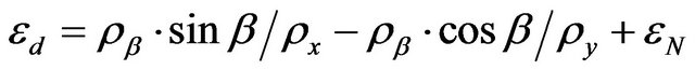
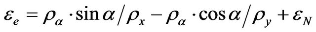
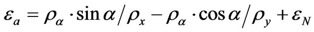
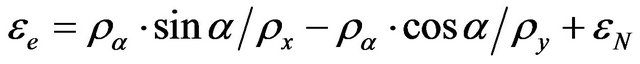
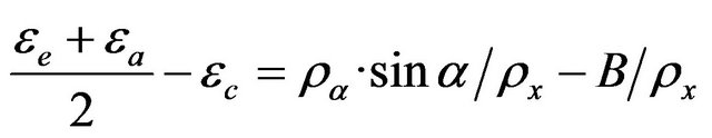
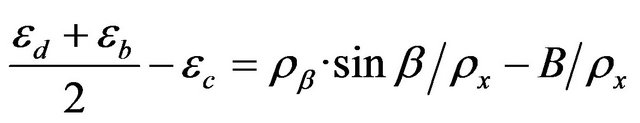
According to the equation of strain compatibility, the strain at a, b, c, d, e can be described as below:
 (10)
(10)
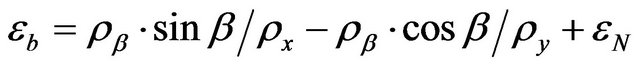 (11)
(11)
 (12)
(12)
 (13)
(13)
 (14)
(14)
2.4. Model Summary
In summary, the model including 7 known quantities: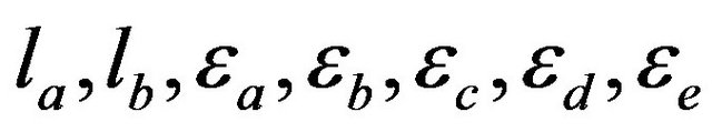 , details are shown in Table 1.
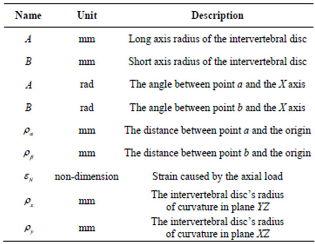
9 unknown quantities: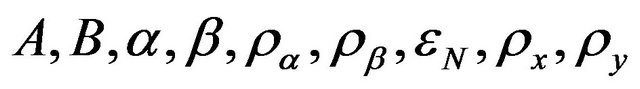 , details are shown in Table 2.
Table 1. Description of known quantity.
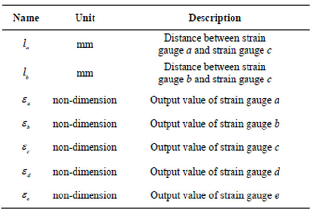
Table 2. Description of unknown quantity.
9 independent equations:
 (5)
(5)
 (6)
(6)
 (8)
(8)
 (9)
(9)
 (10)
(10)
 (11)
(11)
 (12)
(12)
 (13)
(13)
 (14)
(14)
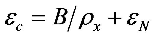
After solving the equation system above, we can bring B and  into the shear strain equation:
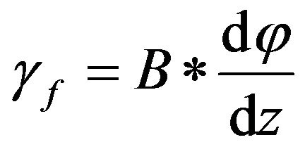 (15)
(15)
Then we can get the parameter describing torsional strain in Z direction: .
.
3. Solution
For convenience, the equation system can be described as below:
 (16)
(16)
 (17)
(17)
 (18)
(18)
 (19)
(19)
 (20)
(20)
 (21)
(21)
 (22)
(22)
 (23)
(23)
 (24)
(24)
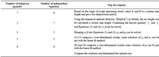
Because the elliptic integral exists in Equations (18) and (19), the equation system is hard to be solved directly. So we assume the long axis radius, short axis radius and angle of the measure point at first and then select the fitting answer. The specific steps were presented in Table 3.
4. Model Modification and Improvement
The model above is theoretical and hypothesis based. Some modification and improvement will make the model more effective and accurate.
Firstly, the error the cylindroid simply introduced into the model needs to be calculated and modificated. Some imaging research tells that the front height of the intervertebral disc is longer than the back height, so an angle about 3˚ - 6˚ exists between the top and bottom surface of the intervertebral disc naturally.
Secondly, the strain gauge should stick on the surface directly. But confined by the biocompatibility and operation time, the strain gauge had to be packed in a biocompatibility flexible board and sticked at the same time. The
Table 3. Solving step of the equation system.
board’s properties especially the thickness will bring some error to the result.
Thirdly, it is hard to modify the model in vivo because of the unavoidable specimen specificity, installation error, model simplification error and follow-up circuit error. It will also lose the real-time advantage. A more effective method is to practice the experiment on cadaveric cervical with both the ellipsoid hypothesis method and the direct pressure measure method. The data of ellipsoid hypothesis method will be adjusted by taking the data from pressure measurement method into consideration. It will enable this new model more convincing when it was taken in vivo.
Last but not least, comparison study with other intervertebral pressure or strain measurement method will make our model more persuasive. Before the whole model and hypothesis can be taken into practice, a good number of experimental data on cadaveric cervical should be studied and parameter in the model should be adjusted.
5. Conclusions
Aiming at getting the strain condition of the intervertebral disc, a mathematic model and a measurement system based on strain gauges were built. In our hypothesis, by only fixing 6 strain gauges on the front side of anintervertebral disc, the complete strain condition and the dimension of the disc can be calculated.
Compared with the former method, the model in this paper is without being damaged and can be operated on the adjacent disc incidentally when a treatment is executed on a patient. It can solve the intervertebral disc strain measure dilemma that direct measure methods can only be executed on a few healthy volunteers and other simulation or indirect measure is too hard to achieve an agreement.
So far, the hypothesis is in exploring stage. We will move to experiment stage and further modify and adjust the model accordingly.
REFERENCES
- J. S. Schwab, D. J. Diangelo and K. T. Foley, “Motion Compensation Associated with Single-Level Cervical Fusion: Where Does the Lost Motion Go,” Spine, Vol. 31, No. 21, 2006, pp. 2439-2448. doi:10.1097/01.brs.0000239125.54761.23
- A. Nachemson and G. Elfstrom, “Intravital Dynamic Pressure Measurements in Lumbar Discs: A Study of Common Movements, Maneuvers and Exercises,” Scandinavian Journal of Rehabilitation Medicine-Supplement, Vol. 1, 1970, pp. 1-40.
- O. Perey, “Fracture of the Vertebral End-Plate in the Lumbar Spine,” Acta Orthopaedica Scandinavica-Supplementum, Vol. 25, 1957, pp. 1-101.
- V. K. Goel and J. N. Weinstein, “Time Dependent Biomechanical Response of the Spine,” In: V. K. Goel and J. N. Weinstein, Eds., Biomechanics of the Spine: Clinical and Surgical Perspective, CRC Press, Boca Raton, 1990, pp. 35-37
- S. Gracovetsky, H. F. Farfan and C. Lamy, “The Mechanism of the Lumbar Spine,” Spine, Vol. 16, No. 3, 1981, pp. 249-262. doi:10.1097/00007632-198105000-00007
- R. N. Natarajan, J. H. Ke and G. B. J. Andersson, “A Model to Study the Disc Degeneration Process,” Spine, Vol. 19, No. 3, 1994, pp. 259-265. doi:10.1097/00007632-199402000-00001
- H. J. Wilke, P. Neef, M. Caimi, T. Hoogland and L. E. Claes, “New in Vivo Measurements of Pressures in the Intervertebral Disc in Daily Life,” Spine, 1999, Vol. 24, No. 8, pp. 775-762.
- J. Calisse, A. Rohlmann and G. Bergmann, “Estimation of Trunk Muscle Forces Using the Finite Element Method and in Vivo Loads Measured by Telemeterized Internal Spine Fixation Devices,” Journal of Biomechanics, Vol. 32, No. 7, 1999, pp. 727-731. doi:10.1016/S0021-9290(99)00052-4
- H. F. Farfan, “Form and Function of the Musculoskeletal System as Revealed by Mathematical Analysis of the Lumbar Spine: An Assay,” Spine, Vol. 20, No. 13, 1995, pp. 1462-1474. doi:10.1097/00007632-199507000-00004
- E. Y. S. Chao, K. N. An and W. P. Cooney, “Instrumented Devices for Joint and Muscle Force Measurement,” In: N. Berme and A. Cappozzo, Eds., Biomechanics of Human Movement: Applications in Rehabilitation Sports and Ergonomics, Bertec Corporation, Worthington, 1990, pp. 86-89