Wireless Engineering and Technology
Vol.05 No.04(2014), Article ID:50343,9 pages
10.4236/wet.2014.54012
An Investigation of Wideband Rectennas for Wireless Energy Harvesting
Jing-Wei Zhang, Yi Huang, Ping Cao
Department of Electrical Engineering and Electronics, University of Liverpool, Liverpool, UK
Email: zjw131@hotmail.com
Copyright © 2014 by authors and Scientific Research Publishing Inc.
This work is licensed under the Creative Commons Attribution International License (CC BY).
http://creativecommons.org/licenses/by/4.0/


Received 7 July 2014; revised 9 August 2014; accepted 27 August 2014
ABSTRACT
This paper is focused on a wireless energy harvesting system using a rectifying antenna (rectenna). The proposed device consists of a wideband cross-dipole antenna, a microwave low-pass filter and a doubling rectifying circuit using Shottcky diodes as rectifying elements. Previously, a few of wideband rectennas have been investigated at 1.7 to 2.5 GHz. The originality of this paper is on the new wideband rectenna design which can harvest the ambient radio frequency (RF) power at 1.7 to 2.5 GHz. In this system, a new wideband cross dipole is designed and used to achieve the required bandwidth and duel-polarization. In addition, the voltage doubling rectifying circuit is optimized to achieve the best performance at power density levels < 200 μW/cm2 which are typical in urban environments. The characteristics of the proposed rectenna over the desired frequency range are investigated, and the integrated rectenna is simulated, made and tested for low input power densities from 5 to 200 μW/cm2. The simulation and measurement results of the rectenna are compared and a good agreement is achieved. The results demonstrate that the maximum rectenna conversion efficiency is nearly 57% around 1.7 GHz and over 20% over the wideband of interest for the incident power density of 120 μW/cm2. It is noted that the impedance matching is one of the main factors affecting the rectenna energy conversion efficiency. This new wideband rectenna has great potential to harvest wireless energy in GSM/3G/4G and ISM 2.4 GHz bands.
Keywords:
Rectennas, Wireless Energy Harvesting, Wideband Dipoles, Rectenna Conversion Efficiency

1. Introduction
With the rapid progress of wireless communications, there have been many wireless systems developed and installed in our cities. The Radio Frequency (RF) power density has become quite considerable in many areas. Currently, the RF energy harvesting has attracted much attention to supply power for some small devices such as wearable and battery-free sensors [1] - [3] . The core device of such a wireless energy harvesting system is the rectifying antenna which is also called as the rectenna. The rectenna is a combination of a rectifier and an antenna, and can receive electromagnetic waves and convert them to direct current (DC). The block diagram of a rectenna device is plotted in Figure 1 which consists of an antenna, a microwave low-pass filter (MLPF)/mi- crowave band-pass filter (MBPF), a rectifier, a DC filter and a load. The receiving antenna connects the MLPF/MBPF which matches the impedance of antenna to the impedance of rectifier and prevents higher order harmonics generated by the rectifier (diodes) re-radiating back to the free space by the antenna. The cut-off frequency of filters is slightly higher than the fundamental frequency. In addition, the DC filter effectively provides a short circuit for the alternative current (AC) and allows the DC current passing to the load which is placed at the output port to measure the output power.
A key performance indicator for a rectenna is the rectenna energy conversion efficiency which is not only of practical importance but also a useful tool to analyze the system performance. This efficiency (η) is a product of the antenna and the rectifier efficiency ηa and ηr, that is,
 (1)
(1)
where ηa is the antenna total efficiency and ηr is the conversion efficiency of the rectifier. This term includes both circuit and rectifying diode losses.
Previously, a range of rectennas have been investigated such as dipole rectennas [4] - [6] , patch rectennas [7] , spiral rectennas [8] , and slot rectennas [9] . Most of these rectenna designs are for narrowband operations (typically around the 2.5 GHz ISM band) for relatively high input power density (>0.5 mW/cm2) applications and very high conversion efficiencies (over 60%) were achieved. However, they produce very low conversion efficiency for low-power density levels and not suitable for RF energy harvesting applications. It is very important to note that most of the power in air in the RF spectrum is in GSM, 3G and Wi-Fi frequency bands [10] . Since a wideband rectenna can capture more wireless energy in air than a narrowband rectenna, a wideband rectenna covering 1.7 to 2.4 GHz with relatively high conversion efficiency for low-input energy harvesting is of great interest.
In this paper, a new wideband integrated rectenna is proposed to achieve a good performance from 1.7 to 2.5 GHz to cover most of the GSM, 3G, LTE (4G) and Wi-Fi services. The design is particularly suitable for applications with a low-input power density (<0.2 mW/cm2). This paper is organized as follows: Section 2 briefly discusses the design of a wideband rectenna system and demonstrates the performance of the wideband cross dipole antenna, the microwave low-pass filter and the rectifier. A wideband dipole is optimized to achieve the required bandwidth. A microwave low-pass filter is designed to prevent higher order harmonics and the voltage doubling rectifying circuit is characterized for a low input power. In Section 3, the wideband rectenna is implemented and measured in anechoic chamber and outdoor environments. Moreover, the results of rectenna conversion efficiency and the DC output voltage are presented and analyzed. Finally, the conclusion is drawn in Section 4.
2. The Rectenna Design and Analysis
A major problem in the rectenna design is how to deal with the frequency-dependent impedance of the antenna and the rectifier. For the maximum power transfer, the impedance of an antenna must match with the impedance of the rectifying circuit. In this Section, a wideband rectenna for wireless energy harvesting is designed and investigated. A rectenna system can be separated into three parts which are a receiving antenna, a microwave low-pass filter and a rectifying circuit as shown in Figure 1. Furthermore, higher order harmonics
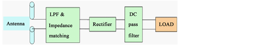
Figure 1. The block diagram of the rectenna device.
produced by the rectifying circuit should be removed by the microwave low-pass filter. In addition, the rectifier is optimized to match the antenna with a filter.
2.1. The Antenna Design
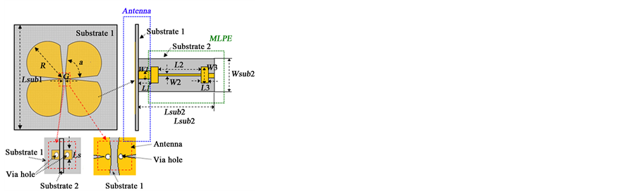
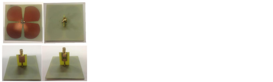
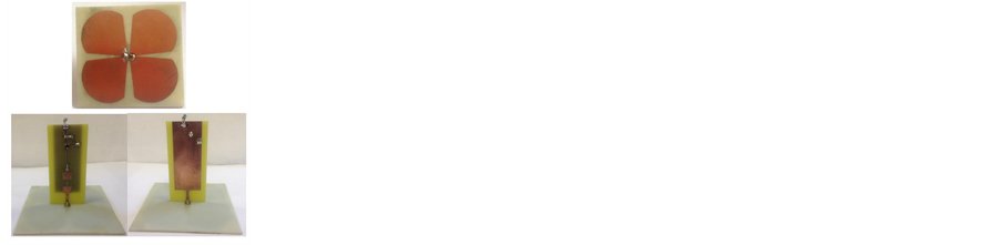
The first step in the rectenna design is to design a wideband antenna with a low-pass filter (to be discussed late) which matches to 50 Ω. A cross-dipole antenna shown in Figure 2(a) was proposed as the receiving antenna for the following reasons. Firstly, the antenna structure with parallel feed lines is convenient to connect with a low-pass filter. Secondly, the antenna has wide bandwidth to receive signals at our frequency region of interest, and thirdly it can receive signals of different polarization which is relatively random in reality.
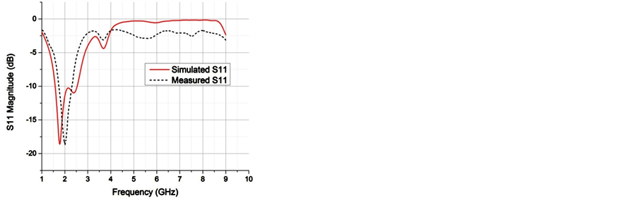
The proposed antenna is fed by a parallel strip line which is on the surface of a dielectric sheet. The detailed characteristics of the parallel strip line can be found in [11] . All the dimensions of the antenna are optimized using CST software package in order to produce the best performance over the frequency range of interest. The length of the proposed and optimized antenna is around 80 mm which is 0.48 λ0 at 1.8 GHz and 0.8 λ0 at 3 GHz. The final dimensions are also given in Figure 2(a). The antenna is built using a low-cost FR4 PCB (printed circuit board) as shown in Figure 2(b). The measured and simulated reflection coefficients of the cross dipole antenna are shown in Figure 3. A good agreement is demonstrated between them, where S11 is less than −10 dB for the frequency band covers from 1.8 GHz to 2.9 GHz. The difference between them around the higher frequencies is mainly due to the cable effects in the measurement. Thus the design requirement is met.
2.2. The Antenna with a Microwave Low-Pass Filter (AMLPF)
A microwave low-pass filter is designed and also shown in Figure 2(a). The low-pass filter has a cutoff frequency around 4 GHz, as shown in Figure 4, to pass signals from 1.8 to 3 GHz and to reject signals above 3.6 GHz, which are the higher order harmonics of operation frequencies.
 (a) (b)
Figure 2. (a) The layout of the rectenna with a low-pass filter. The parameters are: á = 75˚, R = 40 mm, G = 1.5 mm, Ls = 5 mm, Lsub1 = 10 cm, W1 = 2 mm, L1 = 10 mm, W3 = 6.7 mm, L3 = 5.1 mm, W2 = 0.3 mm, L2 = 6 mm, Lsub2 = 30.2 mm, Wsub2= 20 mm. (b) The photograph of the antenna with a low-pass filter.
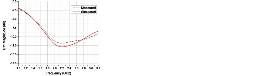
Figure 3. The measured and simulated S11 results of the proposed antenna.
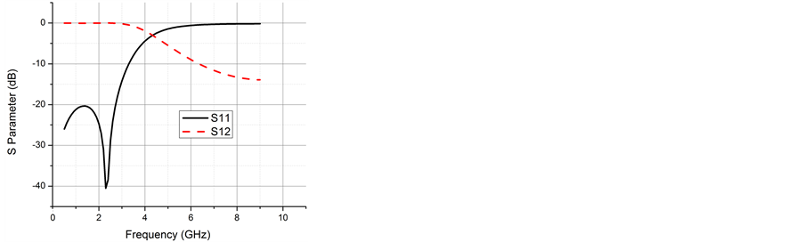
Figure 4. The simulated frequency response of the proposed microwave low-pass filter.
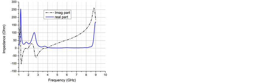
In addition, the microwave low-pass filter connected to the end of the antenna can tune the input impedance of AMLPF. The performance of AMLPF is optimized by using CST software to make sure that it matches with 50 Ω. The layout and photograph of the antenna with a low-pass filter structure are also shown in Figure 2. A SMA connector is connected to the end of the low-pass filter to measure the AMLPF performance. The simulated and measured results are shown in Figure 5(a) and compared to full-wave simulations, a reflection coefficient lower than −8 dB has been measured in frequency range from 1.7 GHz to 2.5 GHz. The discrepancy may be caused by the inaccuracy of the fabrication and the measurement result. It can be seen from the results, which are shown up to 9 GHz to include the frequencies of the 2nd and 3rd higher harmonics, this antenna with a low-pass filter should guarantee a good level of matching over the operation bandwidth while the at second and third harmonics should be well rejected. In addition, the Input impedance of the AMLPF is shown in Figure 5(b) and the desired performance is obtained over the frequency of the interest.
2.3. The Voltage Doubling Rectifying Circuit
As shown in Equation (1), the total conversion efficiency of a rectenna is basically determined by the antenna and the rectifying circuit performance. The goal of this Section is to introduce the voltage doubling rectifying circuit and to investigate its characteristics with the aid of a computer software package, Agilent ADS.
The equivalent circuit of a voltage doubling rectifying circuit is shown in Figure 6. The half-wave voltage doubling rectifying circuit consists of two sections; each comprises a diode and a capacitor for rectification. It functions as follows: on the negative half cycle of the input voltage, capacitor C1 is charged while on the positive half-cycle, the input voltage, in series with the voltage of C1 charges capacitor C2 to the desired output voltage. Capacitor C1, which aides charging capacitor C2, sees alternating current (“AC Cap”) while C2 sees only direct current (“DC Cap”). Thus, the voltage on output capacitor is roughly two times the peak voltage of the diode. The conversion efficiency of a rectifying circuit strongly depends on the converted output voltage. Thus a voltage doubling rectifier circuit has the potential to achieve higher conversion efficiency than a single diode.
To validate such a voltage doubling rectifying circuit, the Schottky HSMS-2852 diode package is chosen because it has a low built-in voltage with a fast switching response and a high cut-off frequency. The voltage doubling rectifying circuit is built on a low-cost double-sided FR4 PCB with the thickness of 1.44 mm and relative permittivity εr of 4.4. Components in the rectifying circuit are connected by a micro-strip transmission line and placed on the top layer of the PCB as shown in Figure 7. In order to match the impedance of rectifying circuit to the AMLPF, all dimensions shown in Figure 7 are optimized by using ADS over the target frequency range and input power levels. The back layer of board is the ground plane. Additionally, the output load is soldered on the edge of output port and two via holes are connected to the ground. The Harmonic Balance simulation has been used in ADS to simulate the rectifying circuit performance. The HSMS 2852 diode package model is imported from the ADS components library. Moreover, the power conversion efficiency ηr for the rectifying circuit is defined as:
 (2)
(2)
where Pin is the input power on the input port, Vdc is the output DC voltage on the output load R.
 (a) (b)
Figure 5. (a) The measured and simulated frequency response of the AMLPF; (b) The simulated input impedance of the AMLPF.
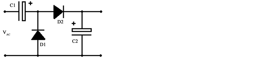
Figure 6. The equivalent circuit of a voltage doubling circuit.
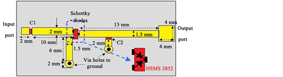
Figure 7. The layout of the voltage doubling rectifying circuit.
According to the IEEE standard for safety levels in general public area, the maximum power density in public area is 0.2 mW/cm2 over the frequency range from 100 MHz to 3 GHz. This power density is low and of great interest to this study. Thus, the power levels from −5 to 10 dBm are the power range of interest, which can be obtained using the conversion equation below:
 (3)
(3)
where the Sd is the power density and Aeff is the effective area of the proposed AMLP.
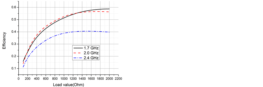
Because of the characteristics of the diode, the input impedance of the doubling circuit is affected by the frequency, the input power level and the output load. The voltage doubling rectifying circuit is optimized by using ADS to achieve the best performance over the power range from −5 to 10 dBm. For our investigation we first fix the input power at 2 dBm, the calculated conversion efficiency as a function of output load is shown in Figure 8(a) for three cases: 1.7, 2.0 and 2.4 GHz, respectively. These three frequencies are important in real applications thus selected in our investigation. For the source impedance, the value of the AMLPF impedance is used in the simulation.
 (a) (b)
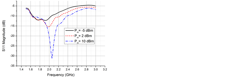
Figure 8. (a) The conversion efficiency for the rectifying circuit as a function of the output load resistance; (b) The simulated reflection coefficient of the voltage doubling circuit for various input power.
It should be noted that the conversion efficiency reaches the maximum value of 40% when the load is around 1400 Ω at 2.4 GHz. When the output load is around 1800 Ω the conversion efficiency has a peak value of 57% at 2.0 GHz. Moreover, at 1.7 GHz the conversion efficiency gradually increases with the load value. The peak efficiency is a function of the load as well as the frequency. Figure 8(b) gives the reflection coefficient of the proposed circuit with the AMLPF impedance. It is clear that the impedance band for S11 < −10 dB for the doubling rectifying circuit is from 1.63 to 2.24 GHz for the input power of 2 dBm. Hence, the conversion efficiency at 2.4 GHz is lower than the conversion efficiency at 1.7 and 2 GHz due to the impedance mismatch. Furthermore, it is clear that the proposed rectifier can roughly meet our required bandwidth over the power range of −5 to 10 dBm. It is also shown that the lower the input power the narrower the bandwidth which is one of the challenges to develop a broadband rectenna.
When we fixed the load value at 1100 Ω, the conversion efficiency including the voltage doubling rectifying circuit as a function of the input power for various frequencies is plotted in Figure 9. It is obvious that efficiencies increase with input power and reach the peak with the input power around 8.5 dBm due to the characteristic of the rectifying diodes [12] . In addition, a part of the incident power is lost due to the source to the doubling rectifier impedance mismatching and the RF to DC rectifier conversion. Thus, choosing suitable antenna impedance will have a great impact on the rectifier power conversion performance.
3. The Rectenna Implementation and Measurements
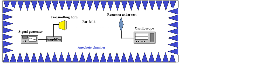
The rectenna is formed using the proposed wideband dipole antenna with the microwave low-pass filter and the voltage doubling rectifying circuit as shown in Figure 10(a). Although, in practice, the rectenna is used to harvest the RF power radiated by ambient sources with power levels fluctuating across the target frequency range, a laboratory measurement system shown in Figure 10(b) is selected to characterize the rectenna over the frequency range of interest, thus we have full control of the measurement for the frequency, incident power level and wave polarization. The source for the measurement was an Agilent signal generator connected a 30 dB power amplifier; thus far field measurements could be performed for a range of incident power levels using the integrated rectenna at different incidence. A broadband double ridged horn antenna was used for transmitting power from 1.6 to 2.8 GHz. Furthermore, the proposed rectenna was placed in a fixed position and the output voltage Vdc over the load R = 1100 Ω was measured using an oscilloscope. The rectenna was placed at a distance of 0.6 m from the horn to the rectenna under test. The total conversion efficiency of the rectenna can be obtained using
 (4)
(4)
The effective area of the antenna Aeff can be calculated using
 (5)
(5)
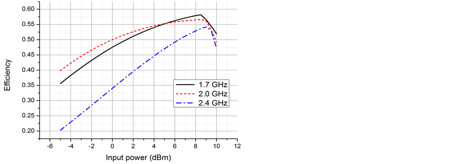
Figure 9. The conversion efficiency of the rectifying circuit as a function of output load with various input power at 2.4 GHz.
 (a) (b)
Figure 10. (a) Photographs of the proposed rectenna under test. (b) The measurement system in anechoic chamber.
where Sd is the power density, Gr is the gain of the proposed antenna and λ0 is the wavelength for the operation frequency. Before the measurement, the measurement system has been calibrated to remove the attenuation caused by cables and connections.
Firstly, the polarization of the rectenna is investigated. Figure 11 shows the measured conversion efficiency of the rectenna as a function of the frequency for three polarization angles. It can be seen that a similar conversion efficiency is obtained for two orthogonal positions of the antenna with the polarization angles β = 45˚ and β = 135˚. The differences are most likely resulted from the fabrication error and asymmetric feeding structure. It is confirmed that the proposed rectenna is a dual-polarized rectenna. In addition, the rectenna has highest conversion efficiency over the frequency range with the polarization angle β = 90˚.
Secondly, the rectenna is studied for the polarization angle β = 90˚. Measured and simulated results of the integrated dipole rectenna are presented in Figure 12. It is clear that the rectenna has the conversion efficiency from 28% to 57% with incident power densities varying from 5 μW/cm2 to 200 μW/cm2 (around −5 dBm to 10 dBm in terms of the power) at 1.7 GHz. In the same power density range, conversion efficiencies change from 16% to 40% and 5% to 24% at 2.0 and 2.4 GHz, respectively. There are good agreements between the simulated and measured results. The measured efficiency was slightly lower than the simulated due to the inaccuracy of the fabrication, the connector and the material (FR4) losses on the rectifier at higher frequencies. Moreover, since the measured efficiency follows closely with the simulated efficiency, higher order harmonics re-radiation at those frequencies is quite low which is expected from the reflection coefficient plot of the antenna integrated with the low-pass filter in Figure 5.
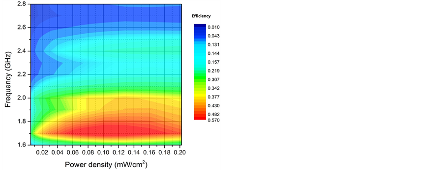
The measured conversion efficiency and output voltage of the rectenna for different input power densities and frequencies are depicted in Figure 13(a) and Figure 13(b). It is seen that the maximum conversion efficiency of 57% is achieved with the input power density of 120 μW/cm2 at 1.7 GHz. From the power conversion point of view, due to relatively high power conversion efficiency (>20%) the optimum operational frequency range of the proposed rectenna is found to be 1.6 to 2.4 GHz at a power density of 200 μW/cm2. Indeed, the rectenna op-
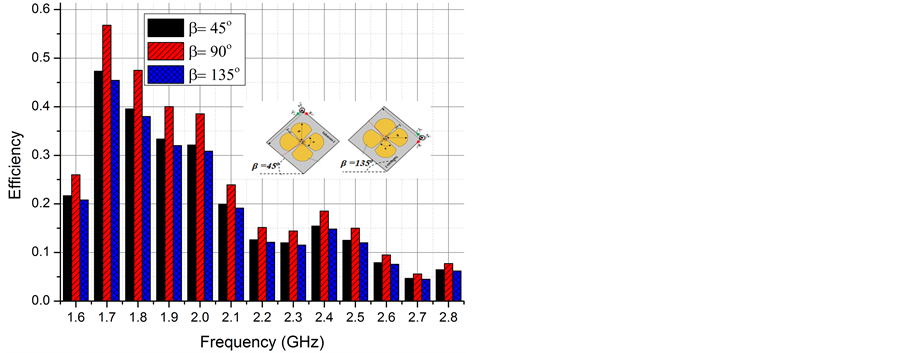
Figure 11. The Measured conversion efficiency for the proposed rectenna for the power density of 120 μW/cm2.
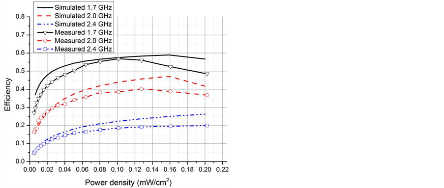
Figure 12. Measured conversion efficiency as a function of power density at 1.7, 2.0 and 2.4 GHz, respectively.
 (a) (b)
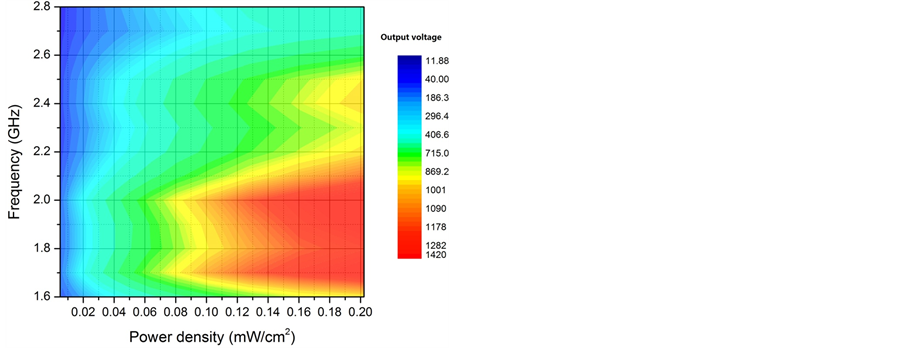
Figure 13. (a) Measured conversion efficiency for wideband rectenna for different power densities with R = 1100 Ω; (b) Measured output voltage (in mV) for wideband rectenna at broadside for power densities from 5 to 200 μW/cm2.
erational bandwidth approximately matches with the bandwidth of the doubling rectifying circuit and the bandwidth of the AMLPF. Furthermore, it can noticed that the conversion efficiencies shapely decrease over a higher frequency range (2.5 GHz - 2.8 GHz), which mainly result from the mismatch of the antenna and the rectifier and the performance of the AMLPF. Figure 13(b) shows the measured DC output voltage of the rectenna as a function of the frequency and power density. Over the frequency band of interest, the output voltage stays above 400 mV over the range of power densities of 30 to 200 μW/cm2.
In addition, a measurement was taken in the University of Liverpool for ambient wireless energy harvesting. The rectenna was tested in an outdoor environment which is so empty that no buildings around shield the visual field. Power sources were a cell phone base station and Wi-Fi systems. The distance between the rectenna and the base station was around 500 m. The output voltage was measured by using a DC meter. The measured output voltage of the rectenna was around 100 mV most of the time and it could also reach more than 120 mV sometimes due to the variation of ambient RF energy. It confirmed that, in practice, the proposed rectenna also can indeed convert the wireless power generated by various systems
4. Conclusion
A dual-polarized wideband rectenna with a good conversion performance has been demonstrated through both simulation and experiment in this paper. The wideband antenna has been designed and optimized for energy harvesting. In addition, an integrated AMLPF has been demonstrated to block higher order harmonics. For maximum power transfer, the voltage doubling rectifying circuit has been designed to match with the AMLPF over power levels of interest. The study has confirmed that the impedance matching between the AMLPF and the rectifying circuit can effectively improve the rectenna conversion efficiency. Moreover, the proposed rectenna has achieved maximum conversion efficiency around 57% at 1.7 GHz and overall conversion efficiency over 20% has been achieved over the frequency range from 1.6 to 2.5 GHz. The new rectenna not only covers a wide operation bandwidth but also has a good performance for the low input power density (<200 μW/cm2). The performances are confirmed through both simulated and measured results which demonstrate that the proposed rectenna has potential to harvest the wireless energy over a wide bandwidth.
References
- Monti, G., Corchia, L. and Tarricone, L. (2013) UHF Wearable Rectenna on Textile Materials. IEEE Transactions on Antennas and Propagation, 61, 3869-3873. http://dx.doi.org/10.1109/TAP.2013.2254693
- Georgiadis, A., Collado, A., Via, S. and Meneses, C. (2011) Flexible Hybrid Solar/EM Energy Harvester for Auto- nomous Sensors. Microwave Symposium Digest (MTT), IEEE MTT-S International, Baltimore, 5-10 June 2011, 1-4.
- Chin, C.H.K., Xue, Q. and Chan, C.H. (2005) Design of a 5.8-GHz Rectenna Incorporating a New Patch Antenna. IEEE Antennas and Wireless Propagation Letters, 4, 175-178. http://dx.doi.org/10.1109/LAWP.2005.846434
- Sun, H., Guo, Y., He, M. and Zhong, Z. (2012) Design of a High-Efficiency 2.45-GHz Rectenna for Low-Input-Power Energy Harvesting. IEEE Antennas and Wireless Propagation Letters, 11, 929-932. http://dx.doi.org/10.1109/LAWP.2012.2212232
- Young-Ho, S. and Kai, C. (2002) A Novel Dual Frequency Rectenna for High Efficiency Wireless Power Transmission at 2.45 and 5.8 GHz. IEEE Microwave Symposium Digest, 2, 1297-1300.
- Brown, W.C. and Triner, J.F. (1982) Experimental Thin-Film, Etched-Circuit Rectenna. IEEE Microwave Symposium Digest, Dallas, 15-17 June 1982, 185-187.
- Falkenstein, E., Roberg, M. and Popovic, Z. (2012) Low-Power Wireless Power Delivery. IEEE Transactions on Micro- wave Theory and Techniques, 60, 2277-2286. http://dx.doi.org/10.1109/TMTT.2012.2193594
- Hagerty, J.A., Helmbrecht, F.B., McCalpin, W.H., Zane, R. and Popovic, Z.B. (2004) Recycling Ambient Microwave Energy with Broad-Band Rectenna Arrays. IEEE Transactions on Microwave Theory and Techniques, 52, 1014-1024. http://dx.doi.org/10.1109/TMTT.2004.823585
- Monti, G., Tarricone, L. and Spartano, M. (2011) X-Band Planar Rectenna. IEEE Antennas and Wireless Propagation Letters, 10, 1116-1119. http://dx.doi.org/10.1109/LAWP.2011.2171029
- Pinuela, M., Mitcheson, P.D. and Lucyszyn, S. (2013) Ambient RF Energy Harvesting in Urban and Semi-Urban En- vironments. IEEE Transactions on Microwave Theory and Techniques, 61, 2715-2726. http://dx.doi.org/10.1109/TMTT.2013.2262687
- Wheeler, H.A. (1964) Transmission-Line Properties of Parallel Strips Separated by a Dielectric Sheet. IEEE Transac- tions on Microwave Theory and Techniques, 13, 173-185.
- Yoo, T.W. and Kai, C. (1992) Theoretical and Experimental Development of 10 and 35 GHz Rectennas. IEEE Tran- sactions on Microwave Theory and Techniques, 40, 1259-1266. http://dx.doi.org/10.1109/22.141359