Wireless Engineering and Technology
Vol. 4 No. 1 (2013) , Article ID: 27640 , 4 pages DOI:10.4236/wet.2013.41001
Mixers of Ultra-High Gain from 5.0 to 18.0 GHz
![]()
1Department of Electronics Engineering, Ming Hsin University of Science and Technology, Hsin-Chu City, Chinese Taipei; 2Department of Electrical Engineering, National Tsing-Hua University, Hsin-Chu City, Chinese Taipei.
Email: hcyang@must.edu.tw
Received July 26th, 2012; revised September 4th, 2012; accepted September 18th, 2012
Keywords: Gilbert Cell Mixer; P1dB; Linearity; Noise Figure (NF); Conversion Gain; Isolation
ABSTRACT
Mixers in the communication system provide the possibility of encoding and decoding radio-frequency EM waves with signals through the help of local oscillators. A mixer with capability of high conversion gain, good isolation, and good linearity is comparably appreciated. Extensively wide ranges of frequencies, from 5.0 to 18.0 GHz, are to be examined addressing the promising functions of mixers in this study. A TSMC 0.18 μm CMOS model implanted in Agilent ADS is used for the circuit designs. Generated from Gilbert Cell Mixer, the modified circuits take advantage of extra active and passive devices to optimize the conversion gains. Characteristics of high conversion gain over 20 dB or even higher (as high as 29.842 dB at −40 mW RF power at working frequency 6 GHz) and low noise figures (NF) are shown.
1. Introduction
Mixers are indispensable components in transceiver system (transmitter and receiver) in the communication system, providing the possibility of encoding and decoding radio-frequency EM waves with signals through the help of local oscillators. As quoted as “Mixer”, a mixer mixes two input signals with different frequencies and yields an output signal with a specific frequency. A mixer with capability of high conversion gain, good isolation, and good linearity is comparably appreciated.
Traditional Gilbert Cell [1] in Figure 1 composing of six NMOS devices mainly generates two differential currents, namely, iD1 and iD2, flowing through M1 and M2 with the common trans-conductance (gm). In one aspect, the two currents associate the two inputs, one from the local oscillator imposing on the two sets, (M3, M4) and (M5, M6), and the other from RF signals impacting on M1 and M2, as expressed as follows:
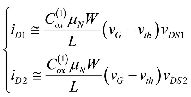 (1)
(1)
with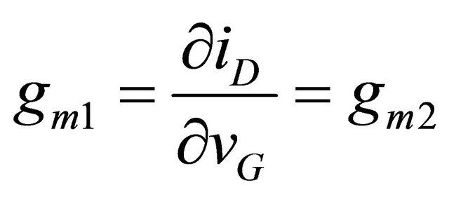 . In Equation (1),
  is oxide capacitance (F/m2),
  is the mobility (m2/sV), and L is the channel length. Because of the multiplication of
 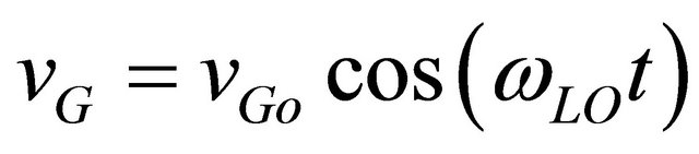 and
and  in Equation (1), the output IFP signals are resulted, as derived in Equation (2), achieving raising and lowering of frequencies, i.e.,
 .
.
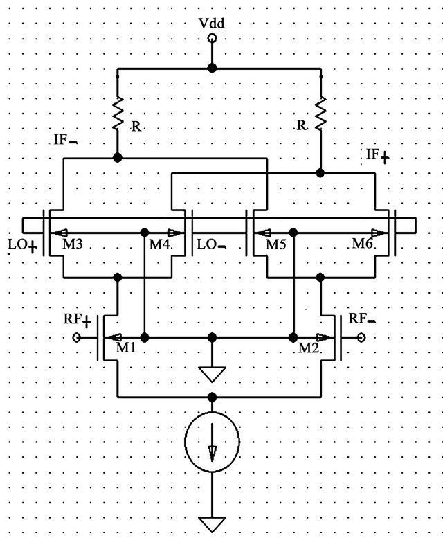
Figure 1. The conventional Gilbert Cell Mixer.
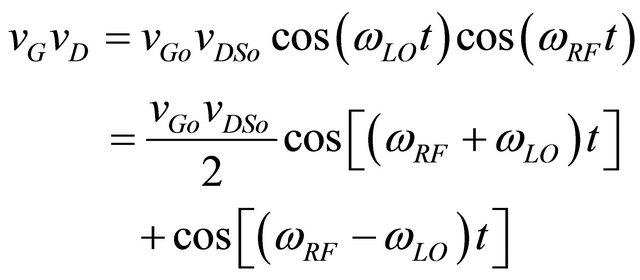 (2)
(2)
In this paper, a powerful mixer using an extensively generated circuit based on Gilbert Cell with sufficient current sources in the downstream is proposed as shown in Figure 2. Somehow, to enhance the stability and the amplification, the symmetrical topology is used by duplicating the unit in Figure 3 on both sides of Figure 2. Advanced Design System (ADS) by Agilent implemented with a TSMC 0.18 micron model is to be used to evaluate the circuit design.
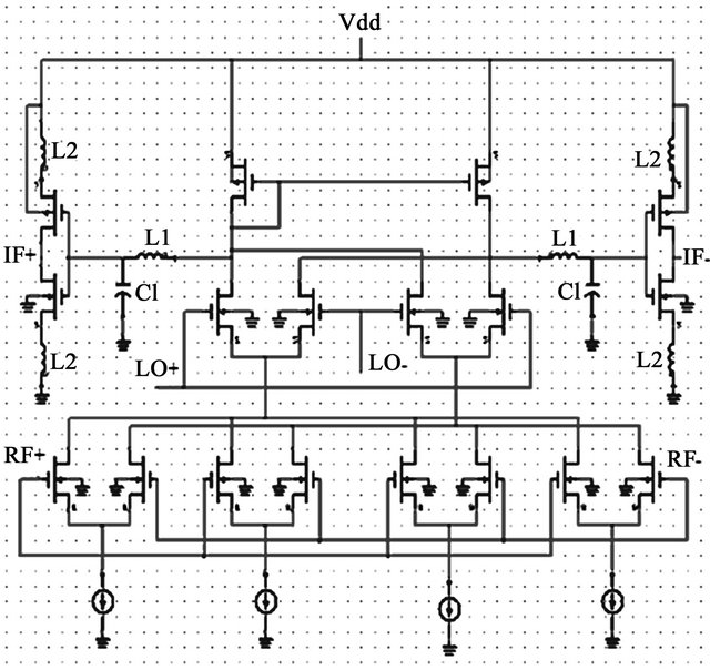
Figure 2. Four-current-source Gilber Cell Mixer with two inverters enhancing the amplifying effects.
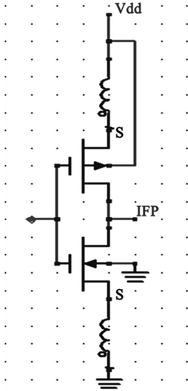
Figure 3. The inverter-like CMOS units.
2. Mixer Circuit Design
For the sake of larger current flow, the circuit in Figure 2 generated from the conventional Gilbert Cell Mixer is to be optimized using four Ibias’s instead of only one Ibias. To avoid the unnecessary power consuming, passive resistors are never considered. With the introduction of inductors and capacitors (L1, and C1), the noise figures are expected to be lowered. And the isolations at higher frequencies ranged from 6 GHz to 18 GHz are supposed to be better because of the two sets of inverter-like units as shown in Figure 3. Each set is inserted with two inductors (L2), one in the upstream and the other in the downstream, to keep the radio frequency signals from leaking. The whole set in Figure 3 is thus operated to raise the conversion gains as well. The symmetrical topology is to be used and the current sources are adjusted step by step. The number of mirror units is to be imposed and the number of symmetrical NMOS devices where LO and RF are applied is carefully examined and determined.
3. Results and Analysis
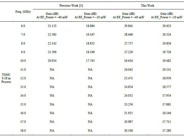
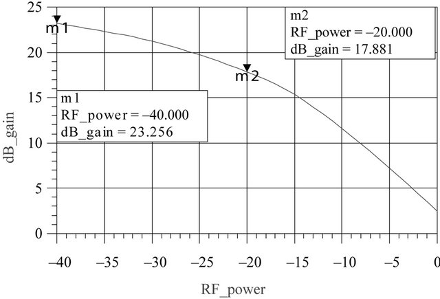
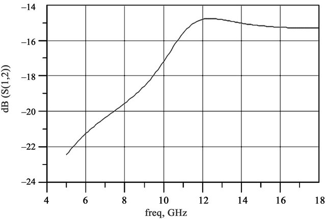
In general, the conversion gains are normally high above 20 dB from 6 GHz to 18 GHz as listed in Table 1, in which the maximum conversion gain can be even as high as almost 30 dB. As shown in Figure 4(a), the exciting results are strongly appreciated at 15 GHz, such as the conversion gains = 23.256 dB at RF_power = –40 mW, 17.881 dB at RF_power = –20 mW, and even over 2.5 dB at RF power = 0 mW. This circuit executes not only the function of a mixer but also enhance the conversion gain, which is quite encouraging and convincing. Two reasons are speculated: 1) the four current sources require higher current to flow through the whole component; and 2) the two inserted inductors in series with the inverterlike CMOS devices keep the high frequency signals from dumping to the ground [2-7]. Figure 4(b) also demonstrates the surprisingly good linearity at such a high frequency from power –40 mW to power –20 mW, extending to about power –15 mW at P1dB point. In addition, the isolations among LO (Terminal 1), RF (Terminal 2), and IF (Terminal 3) are to be found in Figure 5, in which S12 = –15.173 dB, S23 = –28.902 dB, and S13 = –24.783 dB and all are satisfying. Unfortunately, the noise figure NF = 8.400 dB in Figure 6 is not sufficiently low as expected. Nevertheless, it is still controllable and is expected to be lowered in the near future.
4. Discussions
The last two columns of Table 1 show the encouraging conversion gains up to 18 GHz at RF_power = –40 mW and at RF_power = –20 mW. As compared to the previous work in [8], the conversion gains can be even
Table 1. Comparisons of the previous work and this work.
 (a)
(a)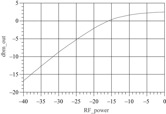 (b)
(b)
Figure 4. (a) The conversion gain; and (b) the linearity.
noticeably better from 6 GHz to 10 GHz. It is due to careful tuning on the passive devices and the stable symmetrical topology, which can be seen in the mirror feature. In addition, the inverter-like CMOS devices with inductors in series play the roles of keeping the high frequency signals away from dumping to the ground, and thus contribute significantly to the conversion gains. The current sources were kept the same at 2 mA for its satisfactory status in this structure compared to the previous design [8]. Somehow, the currents of the four current sources and the voltage of the voltage source are expected to be lower in the continuous work. In the mean time, noise figures are to be lowered in the near future, too, even at such high working frequencies.
 (a)
(a)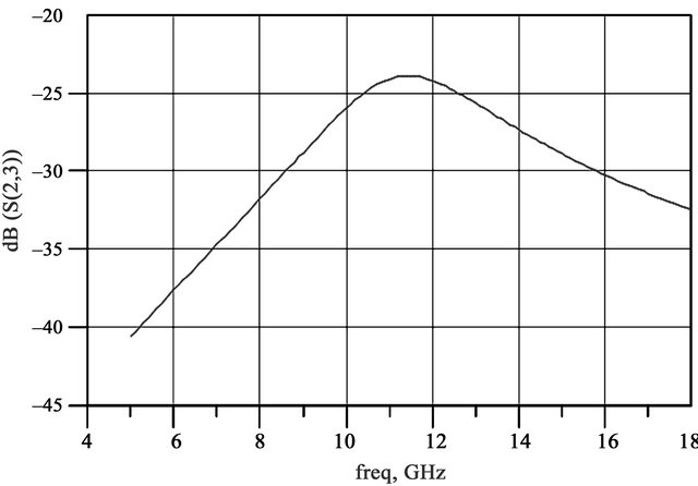 (b)
(b)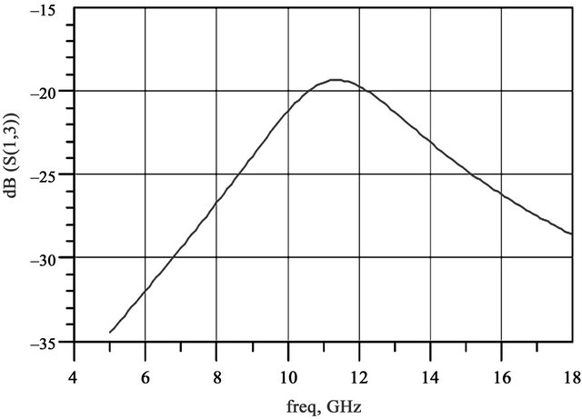 (c)
(c)
Figure 5. The isolation among LO (Terminal 1), RF, (Terminal 2) and IF (Terminal 3) at 15 GHz (a) LO-RF (b) RF-IF (c) LO-IF.
5. Conclusion
A Gilbert-Cell Mixer based mixer is introduced with two inverter-like CMOS units in series with two inductors. The conversion gains are found to be significantly improved. The good isolation, acceptable noise figure, and linearity are to be checked. The encouraging data shows the promising applicable circuit designs. One would continue to develop the total solution for the whole component and
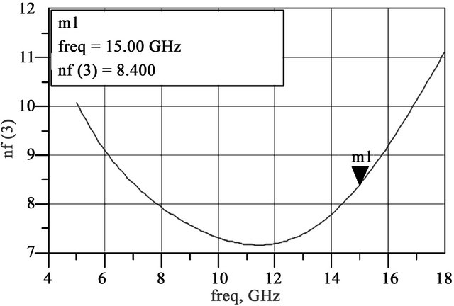
Figure 6. Noise figure at IF at 15 GHz.
even the whole system.
6. Acknowledgements
The authors would like to thank Yi-Chang Cheng for the support. Special thanks are due to all the teaching assistants, Fang-Fang Chen and Ven-Chung Yu.
REFERENCES
- M. T. Terrovitis and R. G. Meyer, “Noise in CurrentCommutating CMOS Mixers,” IEEE Journal of SolidState Circuits, Vol. 34, No. 6, 1999, pp. 772-783. doi:10.1109/4.766811
- K. Choi, D. H. Shin and C. P. Yue, “A 1.2-V, 5.8-mW, Ultra-Wideband Folded Mixer in 0.13-μm CMOS,” IEEE Radio Frequency Integrated Circuits (RFIC) Symposium, Honolulu, 3-5 June 2007, pp. 489-492.
- H. Qi, J. Chen, H. Pan and J. Meng, “A 1.2 V High Linearity Mixer Design,” IEEE ICEMI, Xi’an, 16-18 August 2007, pp. 274-277.
- P. J. Sullivan, B. A. Xavier and W. H. Ku, “Low Voltage Performance of a Microwave CMOS Gilbert Cell Mixer,” Digital Object Identifier, Vol. 32, No. 7, 1997, pp. 1151- 1155
- T.-P. Wang, C.-C. Chang, R.-C. Liu, M.-D. Tsai, K.-J. Sun, Y.-T. Chang, L.-H. Lu and H. Wang, “A Low-Power Oscillator Mixer in 0.18-m CMOS Technology,” Digital Object Identifier, Vol. 41, No. 1, 2006, pp. 88-95.
- E. E. Bautista, B. Bastani, J. Heck and Member IEEE, “A High IIP2 Down Conversion Mixer Using Dynamic Matching,” IEEE Journal of Solid-State Circuits, Vol. 35, No. 12, 2000, pp. 1934-1941. doi:10.1109/4.890307
- A. Q. Safarian, A. Yazdi and P. Heydari, “Design and Analysis of an Ultrawide-Band Distributed CMOS Mixer,” IEEE Transactions on Very Large Scale Integration (VLSI) Systems, Vol. 13, No. 5, 2005, pp. 618-629.
- H.-C. Yang, M.-D. Chang, M.-C. Wang, S.-C. Chi and C.-T. Wang, “3.5 GHz to 10.0 GHz Mixers of High Gains and Good Isolations,” IEEE 7th International Conference on Wireless Communications, Neworking and Mobile Computing, (WiCOM), Wuhan, 23-25 September 2011.