Journal of Environmental Protection
Vol. 3 No. 5 (2012) , Article ID: 19497 , 11 pages DOI:10.4236/jep.2012.35046
The Effect of Generated Chlorine Gas on Electroremediation of Heavy Metals from Offshore Muds
![]()
1Sonny Astani Civil and Environmental Engineering, University of Southern California, Los Angeles, USA; 2Petroleum Institute, Abu Dhabi, UAE; 3Lehigh University, Bethlehem, USA; 4Electropetroleum Inc., Wayne, USA.
Email: *gchling@usc.edu
Received January 20th, 2012; revised February 19th, 2012; accepted March 21st, 2012
Keywords: Offshore Sediments; Chlorine Gas Removal; Electroremediation; Contaminated Muds; Electrokinetic Efficiency
ABSTRACT
The removal efficiency of heavy metals from offshore muds is enhanced in the presence of generated chlorine gas (Cl2). The tests showed a high removal efficiency of heavy metals at the anode end of cores after 24 hours of EK application. In the initial tests, high electrokinetic flow potential was achieved; however, high levels of chlorine gas were produced in the high-salinity environments. The process was improved by controlling and maintaining a certain fraction of the chlorine gas (Cl2) in place. The pH was controlled by the chlorine gas maintained in-situ and transported from the anode to cathode. The transports of four heavy metals were evaluated in this study. The chlorine gas can have two impacts on the transport of metals in the system. One is to oxidize the metal ions to a higher oxidation state and the second is to form chloride complexes, which have higher mobility in the system. Determination of oxidation state and the subsequent metal chloride complex are left for future research.
1. Introduction
Electroremediationof heavy metals from muds have been studied by Haroun (2009) [1], Pamukcu (2009) [2] and Wittle and Pamukcu (1993) [3]. The writers investigated the efficiency of electroremidiation in the presence of chlorine gas produced in high-salinity environment. The sample diameter of cores was 3.81 cm (1.5 inch); pH and temperature were measured continuously. Various voltage gradients were used. The electrokinetics proved to be successful in enhancing oil recovery (EEOR) in actual field tests (Wittle, J.K. et al., 2008; Wittle, J.K. et al., 2011) [4,5].
2. The Algorithm
D.C current, which is determined by voltage gradient, was employed using electrokinetic technology. H+ was produced at the anode (1) and OH– at the cathode (2).
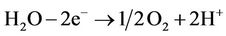 (1)
(1)
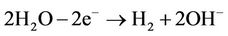 (2)
(2)
These two equations are fundamental reactions at the electrodes occurring in the electrokinetic cell.
The chlorine gas (Cl2) was produced at the anode, together with O2 in the presence of saline water:
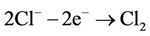 (3)
(3)
The electrokinetic velocity of a fluid of certain viscosity and dielectric constant through a surface-charged porous medium with zeta or electrokinetic potential (ζ), under an electric potential gradient E, is given by the Helmholtz-Smoluchowski (H-S) equation as follows:
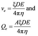 (4)
(4)
where ve = electrokinetic velocity, Qe= electrokinetic flow rate, A = cross-sectional area, D = dielectric constant,  , E = potential difference, and
  viscosity of the fluid.
The ζ potential in Equation (4) has been shown to vary with the pH and ionic concentrations of the pore fluid, as well as the electric field. Therefore, it is not constant during electrokinetic transport in clay medium (Probstein and Hicks, 1993) [6].
3. Apparatus and Procedure
The apparatus consists of two chambers with the anode and cathode electrodes, D.C power supply, solution tanks, volumetric cylinders with gas measurement devices, peristaltic pumps, pressure measurement devices, and digital pH measurement device (Figure 1). The peristaltic pump was employed to control the pH in the cathode chamber (flow rate controller). Gas measurement devices were mounted to determine the amount of gas generated.
The pH was continuously maintained at a value less than 10 at the cathode end. By maintaining the pH at less than 10, the process efficiency improved and scaling at the cathode was minimized. The saline water was flushed through the anode chamber by a peristaltic pump. The pH in the anode chamber was measured continuously and remained at less than about 2.5. Throughout the test the chlorine gas was produced at the anode.
In a closed system, the Cl2 gas was not allowed to escape with resulting increase in pressure, whereas in the open system the Cl2 gas was allowed to escape.
4. Experimental Results
The samples were collected from two different contaminated areas in Abu Dhabi, UAE: 1) offshore muds adjacent to refinery—industrial area and 2) offshore muds in Port area.
Mud samples were sieved using a 1-mm sieve and then compressed in a cylinder 3.81 cm in diameter and 30 cm long for seven days under an applied pressure of 30 psi.
Two samples 30 cm in length were treated continuously with D.C current for 24 hours: sample (1) using open system and (2) using closed system. Two other samples were treated for 40 hours (sample No. 3, open system, and sample No. 4, closed system) with two 8- hour interruptions (total treatment time = 24 hours). Concentrations of As, Cr, Cs, and Zn were determined initially and after EK treatment (ICP-MS).
5. Data Analysis
The experimental results are presented in Figures 2 through 17. Figures 2 through 11 show the results of 24 hour treatment, whereas Figures 12 through 17 show the results after EK treatment applied for 40 hours with two 8-hour interruptions (actual treatment time = 24 hours). Application of potential gradient of 3.5 V/cm in the open system resulted in an increased removal efficiency when compared to application of 3.5 V/cm in the closed system. Higher removal efficiency was obtained by taking advantage of Cl2 gas generated at the anode and transported to the cathode in a closed system. Reduced power consumption with higher volumes of produced water was achieved in the closed system.
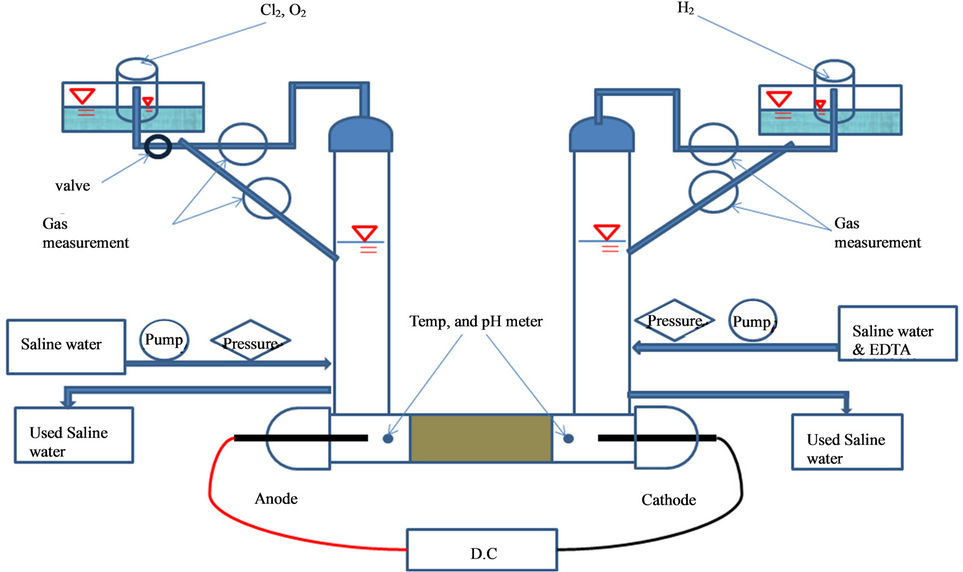
Figure 1. Apparatus used in electroremediation of heavy metals from offshore sediments with equipment for chlorine gas removal.
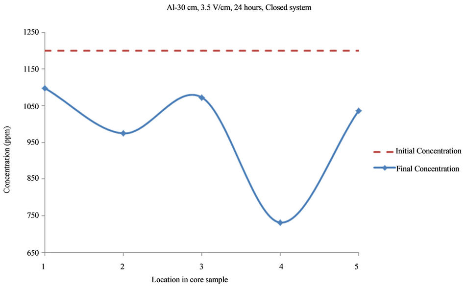
Figure 2. Concentration of Al upon EK treatment along the core length of 30 cm. Potential gradient = 3.5 V/cm, treatment time = 24 hours.
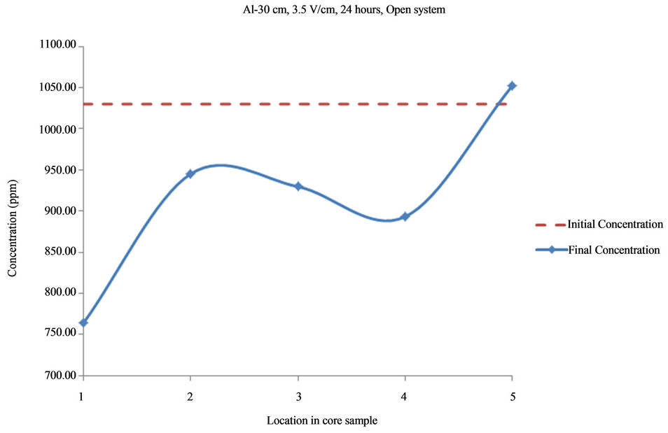
Figure 3. Concentration of Al upon EK treatment along the core length of 30 cm. Potential gradient = 3.5 V/cm, treatment time = 24 hours.
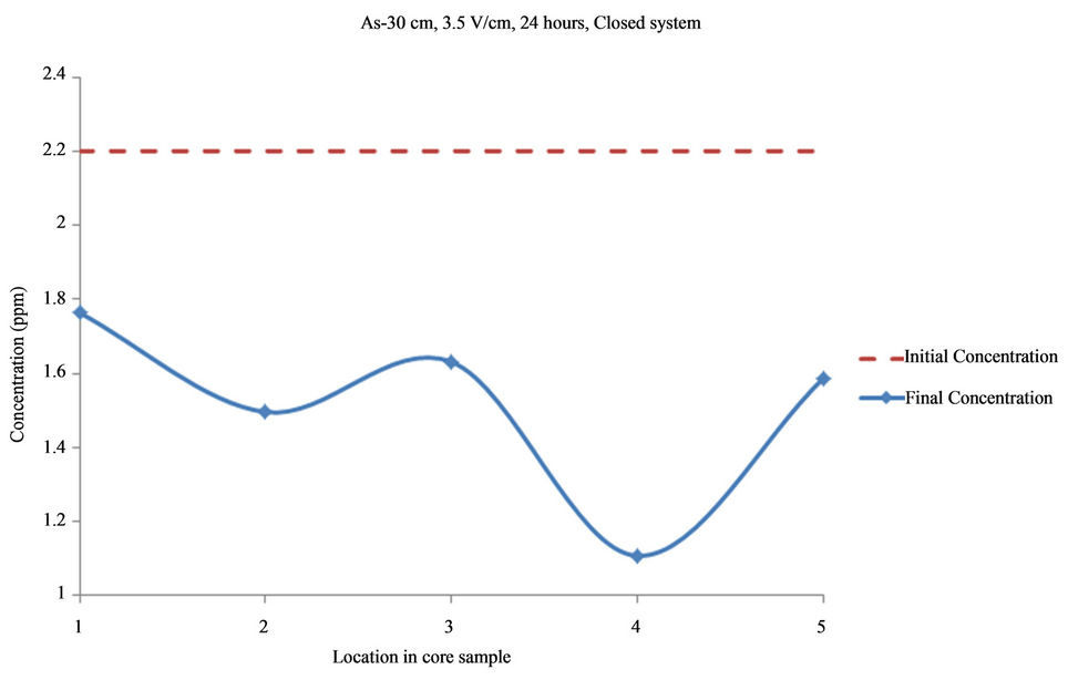
Figure 4. Concentration of As upon EK treatment along the core length of 30 cm. Potential gradient = 3.5 V/cm, treatment time = 24 hours.
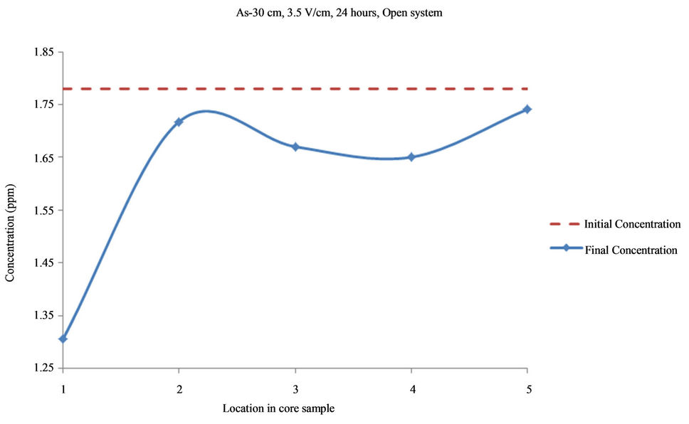
Figure 5. Concentration of As upon EK treatment along the core length of 30 cm. Potential gradient = 3.5 V/cm, treatment time = 24 hours.
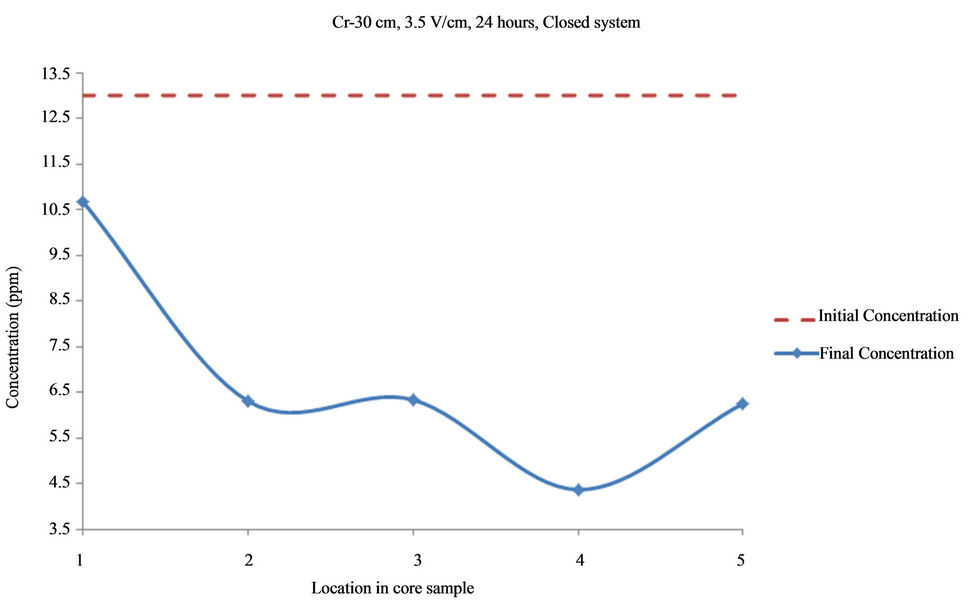
Figure 6. Concentration of Cr upon EK treatment along the core length of 30 cm. Potential gradient = 3.5 V/cm, treatment time = 24 hours.
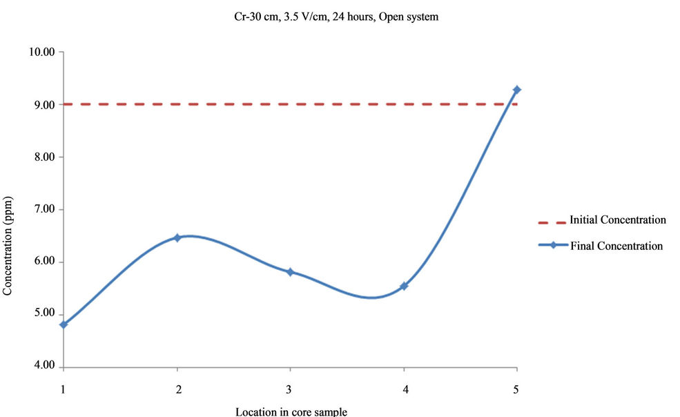
Figure 7. Concentration of Cr upon EK treatment along the core length of 30 cm. Potential gradient = 3.5 V/cm, treatment time = 24 hours.
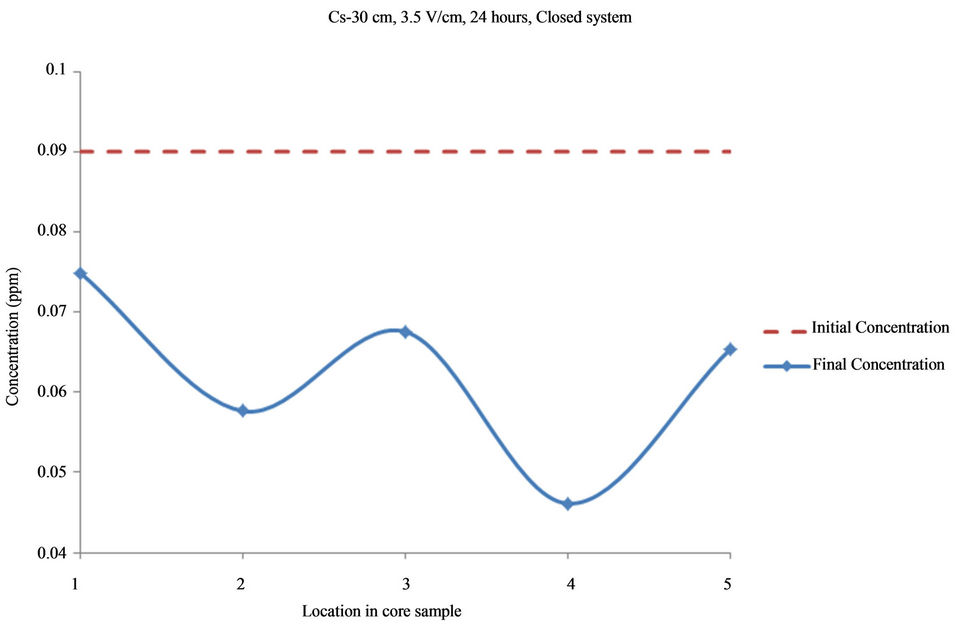
Figure 8. Concentration of Cs upon EK treatment along the core length of 30 cm. Potential gradient = 3.5 V/cm, treatment time = 24 hours.
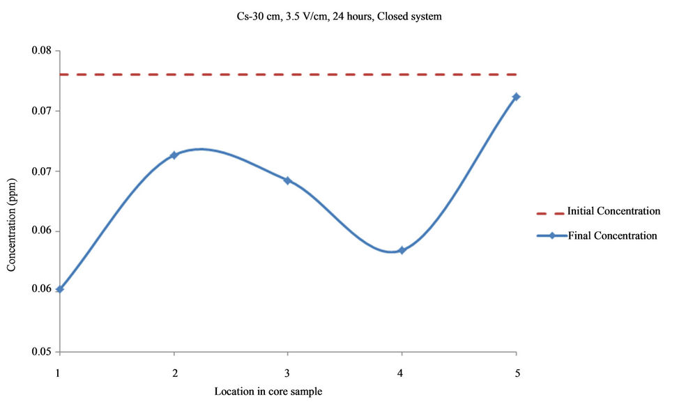
Figure 9. Concentration of Cs upon EK treatment along the core length of 30 cm. Potential gradient = 3.5 V/cm, treatment time = 24 hours.

Figure 10. Concentration of Zn upon EK treatment along the core length of 30 cm. Potential gradient = 3.5 V/cm, treatment time = 24 hours.
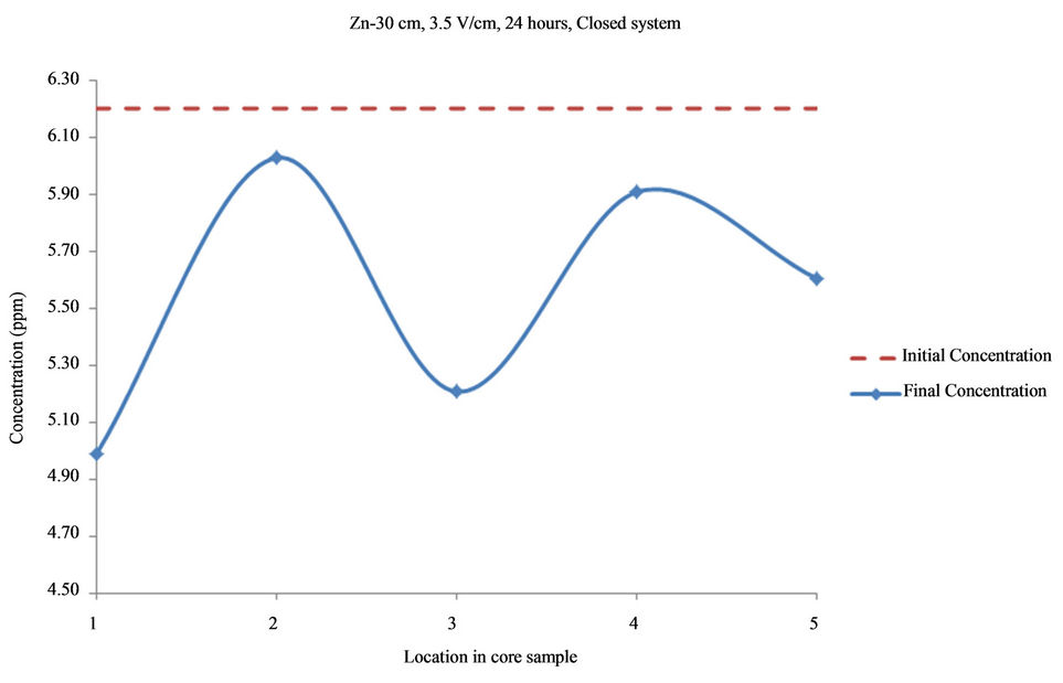
Figure 11. Concentration of Zn upon EK treatment along the core length of 30 cm. Potential gradient = 3.5 V/cm, treatment time = 24 hours.
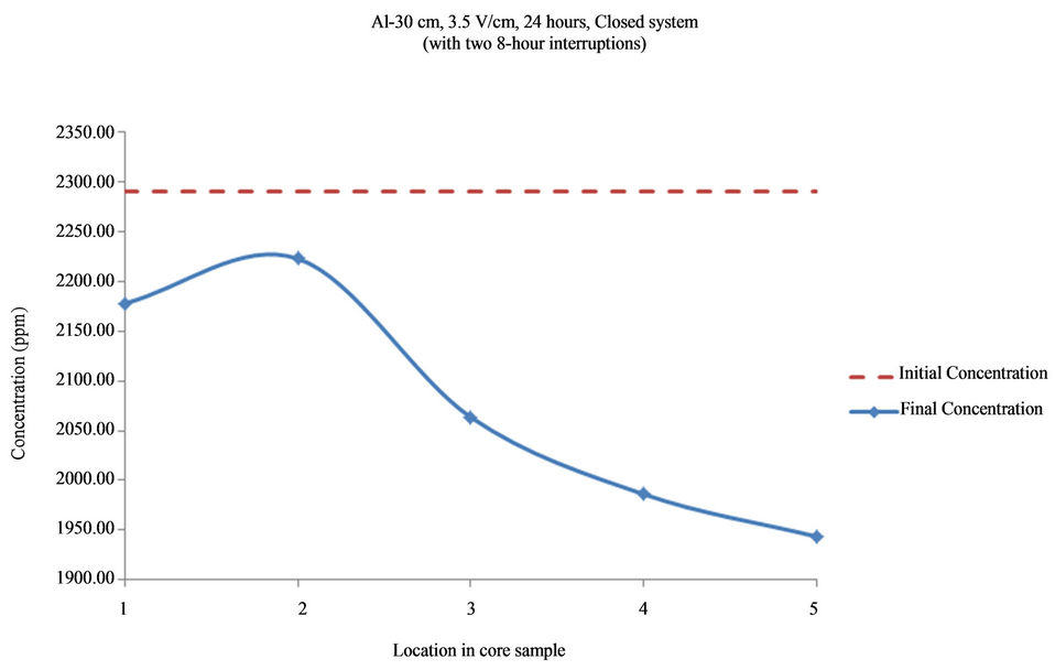
Figure 12. Concentration of Al upon EK treatment along the core length of 30 cm. Potential gradient = 3.5 V/cm, treatment time = 40 hours (with two 8-hour interruptions).
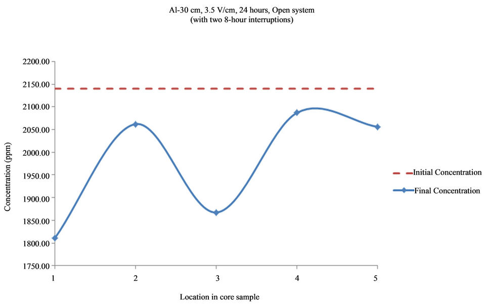
Figure 13. Concentration of Al upon EK treatment along the core length of 30 cm. Potential gradient = 3.5 V/cm, treatment time = 40 hours (with two 8-hour interruptions).
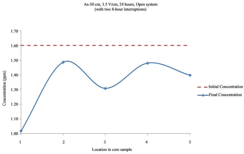
Figure 14. Concentration of As upon EK treatment along the core length of 30 cm. Potential gradient = 3.5 V/cm, treatment time = 40 hours (with two 8-hour interruptions).
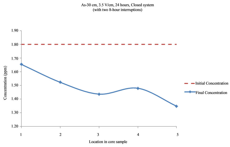
Figure 15. Concentration of As upon EK treatment along the core length of 30 cm. Potential gradient = 3.5 V/cm, treatment time = 40 hours (with two 8-hour interruptions).
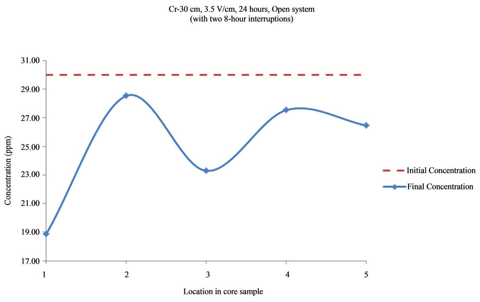
Figure 16. Concentration of As upon EK treatment along the core length of 30 cm. Potential gradient = 3.5 V/cm, treatment time = 40 hours (with two 8-hour interruptions).
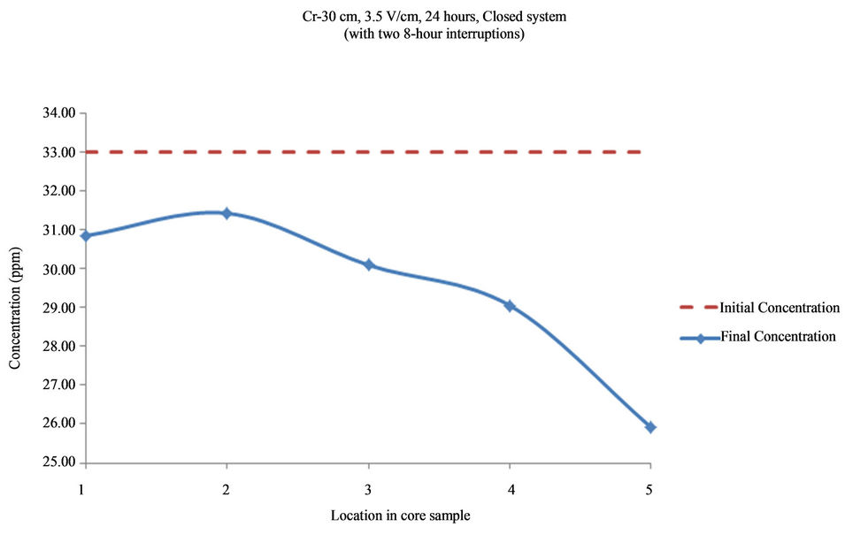
Figure 17. Concentration of As upon EK treatment along the core length of 30 cm. Potential gradient = 3.5 V/cm, treatment time = 40 hours (with two 8-hour interruptions).
Figures 12 through 17 displayed results of a second set of tests to illustrate the effect of chlorine gas on removal efficiency.
The continuous application of D.C in closed system gave better results than interrupted application of D.C. Final pH at the cathode was reduced with the aid of transported Cl2 gas.
6. Conclusions
In the case of tests involving Cl2 gas, in a closed system with a potential gradient of 3.5 V/cm, removal efficiency was higher than in the open system with 3.5 V/cm electric potential. Higher removal efficiency was obtained by using the Cl2 gas generated at the anode and transported to the cathode in a closed system. Reduced power consumption with higher volumes of produced water was achieved in the closed system.
In this study, the continuous application of D.C in closed system gave better results than interrupted application of D.C. Final pH at the cathode was reduced by Cl2 gas. The chlorine gas possibly can have two impacts on the transport of metals in the system. One is to oxidize the metal ions to a higher oxidation state and the second is to form chloride complexes which have higher mobility in the system. In conclusion, it appears that presence of Cl2 gas improves the efficiency of remediation.
7. Acknowledgements
The authors gratefully acknowledge the support of The Petroleum Institute, Abu Dhabi, U.A.E., University of Southern California, CA, USA, Lehigh University, PA, USA, and Electropetroleum Inc., PA, USA.
REFERENCES
- M. H. Haroun, “Feasibility of in-Situ Decontamination of Heavy Metals by Electroremediation of Offshore Muds,” Ph.D. Dissertation, University of Southern California, Los Angeles, 2009.
- S. Pamukcu, “Electrochemical Transport and Transformations,” In: Reddy and Camaselle, Eds., Electrochemical Remediation Technologies for Polluted Soils, Sediments and Groundwater, John Wiley & Sons, New York, 2009, pp. 29-65.
- J. K. Wittle, D. G. Hill and G. V. Chilingar, “Direct Current Electrical Enhanced Oil Recovery in Heavy-Oil Reservoirs to Improve Recovery, Reduce Water Cut, and Reduce H2S Production While Increasing API Gravity,” SPE Western Regional and Pacific Section AAPG Joint Meeting, Bakersfield, 29 March-2 April 2008, 2008, pp. 1-19.
- J. K. Wittle, D. G. Hill and G. V. Chilingar, “Direct Electric Current Oil Recovery (EEOR)—A New Approach to Enhancing Oil Production,” Energy Sources, Part A (Recovery, Utilization, and Environmental Effects), Vol. 33, No. 9, 2011, pp. 805-822.
- J. K. Wittle and S. Pamukcu, “Electrokinetic Treatment of Contaminated Soils, Sludges and Lagoons,” US Department of Energy, Argonne National Laboratories, Argonne, II, DOE/CH-9206, No. 02112406, 1993, p. 45.
- R. F. Probstein and R. E. Hicks, “Removal of Contaminants from Soils by Electric Fields,” Science, Vol. 260, 1993, pp. 498-503. doi:10.1126/science.260.5107.498
NOTES
*Corresponding author.