Smart Grid and Renewable Energy
Vol.08 No.04(2017), Article ID:75770,15 pages
10.4236/sgre.2017.84007
Dynamic Circulation Control for a Vertical Axis Wind Turbine using Virtual Solidity Matching
Jay P. Wilhelm1, Andrew C. Nix2, Chad C. Panther2, Wade W. Huebsch2, James E. Smith2
1Mechanical Engineering Department, Russ College of Engineering and Technology, Ohio University, Athens, OH, USA
2Mechanical and Aerospace Engineering Department, Statler College of Engineering and Mineral Resources, West Virginia University, Morgantown, WV, USA

Copyright © 2017 by authors and Scientific Research Publishing Inc.
This work is licensed under the Creative Commons Attribution International License (CC BY 4.0).
http://creativecommons.org/licenses/by/4.0/


Received: March 11, 2017; Accepted: April 25, 2017; Published: April 28, 2017
ABSTRACT
Vertical Axis Wind Turbines (VAWTs) with fixed pitch blades have a limited power capture performance envelope as the Tip Speed Ratio (TSR) changes. Circulation Control (CC) has been proposed and simulated to possibly increase power capture of a VAWT using constant CC jet momentum, but a practical method of minimizing CC usage has yet to be explored. In addition, VAWTs are typically limited in power capture performance either by a maximum peak at a small set of TSR or wide operating TSR at fractions of the peak performance based on the design solidity. Both the reduced jet usage and solidity limitation were addressed by developing a method of dynamically using CC to perform a virtual solidity change. The developed method described within this work used CC to change blade aerodynamics to specifically match a maximum performing static solidity or wake shape at a given TSR. Simulation results using an existing aerodynamics model indicated a significant reduction in the required CC jet momentum compared to a constant CC system along with control over power capture for a CC-VAWT.
Keywords:
Circulation Control, Vertical Axis Wind Turbine, VAWT, Flow Control, Solidity Matching

1. Introduction
Wind turbines can provide an inexpensive localized renewable power source, supplement an existing supply grid, or provide a stand-alone source of power. The installation and usage of wind turbines have grown at a massive rate over the last decade and are primed to become a large producer of power in the US and abroad [1] [2] . As such, it is desired that wind turbines operate efficiently within their deployment environment of varying wind speeds. A major drawback of Vertical Axis Wind Turbines (VAWTs), thus far, is that power capture cannot be reliably controlled to compensate for changing wind speeds [3] [4] . Therefore, much interest has focused on methods of controlling VAWT blade aerodynamics to increase power capture for a range of wind speeds. A thin injection slot of high velocity air that adheres to a rounded trailing edge due to the Coanda effect, known as Circulation Control (CC), is a possible solution to increasing a VAWT’s power capture. Simulations of constant jet momentum CC were investigated and found to increase the turbine’s coefficient of performance [5] . The problem with constant jet momentum usage for a VAWT is that the power required may exceed the power captured. Dynamic usage of CC was explored to increase performance in a similar manner to the effects of constant CC while using dynamic CC jet momentum. This paper applied a previously developed VAWT aerodynamics model [6] to determine CC jet momentum values required to match solidity or the wake shape through a range of rotational angles and tip speed ratios. Dynamic utilization of CC varied with rotation speed, blade control region, CC schedule, to achieve maximum performance at varying TSR. Results are presented to create a map of required CC jet momentum required versus tip speed ratio and angle of rotation.
1.1. Circulation Control
Wind turbine blade lift control mechanisms that ultimately control power capture have included pitch variation or feathering, trailing edge flaps, vortex-generators, and even plasma systems [3] [4] [7] [8] [9] [10] . During rotation of a VAWT, each blade experiences different flow conditions requiring individual control for maximum efficiency [11] . Excluding plasma actuation by Greenblatt [12] , all of the systems have required some fashion of a moving aerodynamic device or pitching blade to control power generation with varying results and similar conclusions of a complicated and fragile actuation mechanism. Plasma actuation was investigated by Greenblatt [12] and found that its use could increase power capture (~5%) when used on the upwind portion of rotation. Each investigated aerodynamic control method has merit, but ultimately a more reliable and simpler mechanism of controlling blade lift was sought. A possible candidate is the pneumatic trailing edge jet slots that contain the actuation or valving mechanism inside the blade. Jet slots due not require any moving components external to the blade and avoid potential pitching blade failures that currently are limiting VAWT’s such as indicated by Pawsey [3] .
The use of pneumatic devices in the form of trailing edge jets have been employed or been under consideration in the field of aerodynamic flow control dating back to the 1930’s. Trailing edge jets are still being experimented with as a method of flow control [13] [14] [15] [16] [17] along with successful application to aircraft such as the C-17. Implementations include sharp trailing edges of otherwise conventional airfoils that are replaced with rounded or bluff surfaces, with circular cross-sections, containing thin tangential jet slots located on the aft upper surface. Combining the jet with a rounded trailing edge is commonly known as Circulation Control, which has potential to greatly (sometimes a 10x improvement) increase lift generated [13] [16] [18] - [23] . The potential increase in lift and lack of a moving device external to the blade led the authors to focus on development of a method to efficiently use CC to control power capture of a VAWT.
CC is characterized by a non-dimensional parameter, known as the jet momentum coefficient, denoted as  [20] . This coefficient is defined as the ratio of the jet’s momentum to the free stream momentum. The jet momentum coefficient can be combined with the airfoil’s lift to show efficiency, which has an upper limit depending upon airfoil geometry according to Abramson [18] . In regards to a VAWT, CC could be considered a fluid based mechanism to control circulation and when examining lift, the virtual camber of a airfoil. CC is capable of both increasing and decreasing lift using upper and lowers lots respectively.
Wolfe [24] first investigated the concept of a CC-VAWT in the late 1970’s at West Virginia University (WVU). Their CC-VAWT utilized a mostly hollow blade where jet source air was supplied through structural support arms and controlled at the vertical turbine mast. Initially, the jet momentum was controlled using a hub located value and cam system, which proved troublesome to maintain. Interest was lost as other energy technologies outpaced development of the VAWT, but renewed investigations in the effort picked up at WVU in 2008 due to availability of pneumatic values that could be located within the blade. Recently, the concept of using CC to augment lift for increased energy capture was overviewed by Smith [25] and a blade shape and internal pneumatic design was investigated by Graham and Panther [15] [26] . The combination of CC and a VAWT that contains a valving system with upper and lower trailing edge jets has become known as the CC-VAWT within the current effort. VAWT blade design relies upon symmetric airfoils as the blade will experience both positive and negative angles of attack during the upwind and downwind portions of rotation [27] . The internals of a CC-VAWT blade containing an air supply, pneumatic valve, diffuser, and lower and upper slots housed within a 23% ellipse airfoil was conceptualized, shown in Figure 1, using modern valving

Figure 1. Cross-section of a circulation controlled airfoil.
components to first prove possibility of construction. The selected airfoil and envisioned internal air delivery system was known to maximize CC effects and satisfy the symmetrical needs of a VAWT [5] .
1.2. VAWT Non-Dimensional Parameters
Three important non-dimensional parameters must first be discussed regarding VAWTs to gain an understanding of design choices and performance. First, the defining efficiency factor of a wind turbine is the coefficient of performance ( ), defined as the non-dimensional wind turbine power coefficient for a full rotation including all blades, shown in Equation (1) [28] , where the power of the turbine (Pturbine) is normalized by the air density (ρ), wind velocity (V) and swept area of the airfoils (A). The coefficient of performance is the non-dimensional power of the wind turbine. Second, the solidity (σ) is the non-dimensional size factor of a VAWT, and is shown in Equation (2), where Nb is the number of blades, C is the blade chord and R is the turbine radius. Finally, the TSR or λ is the ratio of rotational velocity (ω) to the free stream velocity (V∞), shown in Equation (3). TSR (λ) is used as a non-dimensional speed parameter that allows designers to evaluate turbine rotational speed to wind speed ratio instead of wind speed alone. The parameters σ and λ are combined with blade aerodynamic characteristics and used within a VAWT aerodynamics model to determine Cp.
 (1)
(1)
 (2)
(2)
 (3)
(3)
1.3. Vortex Method VAWT Modeling
An aerodynamic analytical computer simulation model was needed to study power capture for different CC usage configurations of the CC-VAWT. Parameters of interest were the blade angle of attack, and all aerodynamic forces such as lift, drag, normal, and tangential. CFD is a well known and widely used aerodynamic modeling technique, but can be computationally intensive [29] compared to existing and simplified methods of wind turbine modeling. An alternative technique that predates CFD is known as the vortex method and can provide comparable results to experiments in a computationally minimal footprint as demonstrated by previous research [3] [6] [30] [31] . VAWTs are simulated within the vortex method using potential flow models where vortices are shed off the blade during rotation, are moved down wind by the free stream, and influence the blade local velocity that is a combination of the free stream, rotational, and vortex field intensity and direction [6] . The vortex method allows for upwind/downwind blade wake interactions [32] and with proper modifications, aerodynamic blade changes during rotation. Another area that could possibly be simulated is dynamic stall [3] . The effects of dynamic stall and CC have been investigated by Yen [14] and indicate that without dynamic stall capture, the model may over predict power capture for low TSR ( ). The specific dynamic stall characteristics were unavailable for the CC blade design chosen (23% ellipse) and therefore dynamic stall was unable to be included in the CC-VAWT aerodynamics model. All simulations run throughout this paper included two blades, rotational step of 7.5˚, convergence criteria, and induced velocity of a vortex core as defined in [5] .
The effects of constant jet CC were included into a VAWT vortex model in 2009 by Wilhelm [6] . This work showed the performance of a CC-VAWT could be both increased and decreased when using constant momentum coefficients at all times. Simulation results of the vortex model included comparable trends of past models without CC, providing sufficient validation of a 2D version. The model predicted an improved coefficient of performance for a VAWT (<10%) operating with CC blades ( ), relative to the baseline case (
 ). In most cases, the power needed to create a constant or continuous jet momentum exceeded the power captured. Sign and direction convention was defined with rotation being clockwise looking down from the top of the VAWT with the zero degree azimuth rotational origin tangential to the oncoming or free wind, with an operational diagram shown in Figure 2. The VAWT vortex model will serve as the basis to develop a CC dynamic usable method.
1.4. Circulation Control Usage for a VAWT
Examining VAWT Cp versus λ curves for a range of fixed blade pitch VAWT solidities from Wilhelm’s vortex model [33] and Roh [34] it was found that solidity

Figure 2. VAWT diagram with defining parameters.
(σ) affects the peak and width of performance. A trade-off was found where VAWTs can either operate at a lower performance level over a wide λ range or maximum performance at a narrow λ band. The Cp curve tradeoff of narrow width and higher Cp versus wider operating region but lower Cp as TSR changes exists for all static blade VAWTs. A resultant peak Cp curve versus λ for a VAWT can be predicted by performing a parameter study of solidity and  for VAWT using the vortex aerodynamic model [6] . The simulations enable a natural maximum Cp to be identified from a realistic range of solidities at a given TSR, as highlighted in Figure 3, where the inverse TSR (
 ) is used for a more direct correlation to wind speed. The VAWT simulated used 23% thick elliptical shaped blades as suggested from Panther [15] . Higher solidities than σ = 0.2 were unable to be simulated due to numerical breakdowns within the vortex model. The maximum Cp curve identifies a region where peak performance and a wider operating region may be possible if a VAWT was capable of changing solidity.
Realistically, a VAWT installation site will have varying wind speeds and therefore designers must choose solidity to best fit variability of wind speeds and energy capture needs. However, if a VAWT was capable of dynamically changing solidity, then performance could be expanded. The concept of a VAWT changing solidity without any physical changes to the turbine can be referred to as a dynamic virtual solidity change. Although it may be possible to increase performance outside of the natural performance, this study only focused on directly matching performance levels of known solidities. The concept of a virtual solidity change required a method of using CC jet momentum dynamically.
2. Dynamic Utilization of Circulation Control
The information found in literature regarding the impact of VAWT solidities on performance, VAWT aerodynamic modeling, and CC, were combined used to develop a method of dynamically using CC for a VAWT. In order to efficiently

Figure 3. Performance of select VAWT solidities with the maximum shown [33] .
operate a VAWT with CC, several factors such as the effects of CC with a varying  and the effectiveness of a virtual solidity change were investigated.
2.1. CC-VAWT Blade Control Region
The VAWT blade airfoil chosen for this study, profile shown in Figure 1 contains upper and lower trailing edge jets as indicated in a study by Panther [15] that reviewed and recommended a VAWT blade shape with the highest CC lift augmentation. The blade tangential coefficient (ct), a combination of the angle of attack (α), coefficient of lift (cl), and coefficient of drag (cd), shown in Equation (4), is the driving factor for torque generation and in turn the energy capture of a VAWT. The blade’s ct was studied as angle of attack (α) and  change to identify a CC-VAWT “control region”, highlighted in Figure 4. Note that the jet momentum coefficient, (
 ), was limited to values below 8% due to approaching a steep efficiency curve drop off, according to Abramson [18] . Positive values of
  were represented with a use of the top jet slot while negative values indicated that the lower slot was used giving lift addition and reduction, respectively, within the designated “control region”. Within the CC-VAWT “control region”, the ct may be dynamically changed using CC that results in a boost or drop in force. The “control region” is symmetrical centered at the zero angle of attack line, and non-symmetrical with respect to positive and negative
  values. Although only
  aerodynamic data is shown, interpolation at a specific angle of attack will fill in the experimental data gaps for a finer degree of control.
 (4)
(4)
2.2. Dynamic Circulation Control
A method of directly following a the tangential force of a known solidity that produces a maximum Cp at a given TSR was explored by modifying using CC to change the lift and drag coefficients during rotation within the vortex model.

Figure 4. Tangential coefficient “control region” of a 23% CC airfoil.
The blade “control region” or relationship between ct, angle of attack, and  was used to modify blade forces. The tangential force varies with solidity and is a factor along with solidity and TSR that directly determines performance. The ability to modify the tangential forces dynamically during rotation indicates that performance can be varied. In order to achieve control over the Cp during rotation, an examination of the instantaneous Cp with relation to a modified or selected blade tangential force using CC was needed. First, the tangential force (Ft) was normalized to produce a per unit span (b) force expression as
 (5)
(5)
where Vb is the blade velocity. The per unit span tangential force can then be non-dimensionalized into
 (6)
(6)
where Vrel is the blade rotational velocity. The instantaneous single blade coefficient of performance can be computed using the chord-to-radius ratio ( ), TSR (λ), and non-dimensional tangential force (ft),
 (7)
(7)
Combining the Equations ((7) and (6)) leads to an instantaneous single blade coefficient of performance (Cpi) based on the tangential coefficient and can be represented as
 (8)
(8)
Finally, the following expression can be produced, based upon expansion of Equation (8),
 (9)
(9)
where θ is the blade rotational position, and rearranged for an expression of ct as
 (10)
(10)
which can be used to solve for the ct required to match a performance level of a different solidity (σm) from a given initial solidity (σ0) at any point during rotation for a single blade. The overall Cp can then be obtained by integrating or summing the instantaneous Cpi for each blade during rotation. The expression in Equation (10) can be used to search the CC “control region” to identify a  level needed to produce the desired tangential force and in effect, modify the VAWT performance.
2.3. Process Step of CC Solidity Matching for Maximum Cp
1) At a given TSR and initial solidity (σ0), find the solidity (σm) which produces the highest coefficient of performance ( ) from a lookup table (see Figure 8).
2) Solve Equation (10) for ct at given rotational position.
3) Use airfoil aerodynamic data to determine  based upon current α and ct (see Figure 4).
a) Note, ct may not be obtainable, as  is limited to ±8%.
b) A linear interpolation may be used within (α ± 10 deg).
c) As stall is approached or exceeded, a non-linear relationship between  and ct exists and a nearest interpolation is required.
4) Use the calculated  and the airfoil data to determine the value of ct that is achievable.
5) Compute instantaneous single blade coefficient of performance, Cpi for the calculated ct that is achievable.
6) Summate Cpi during rotation to obtain the improved Cp.
2.4. CC Solidity Matching Method Results
The developed CC solidity matching method was first evaluated at a single TSR using a 2D vortex aerodynamics model [6] implemented in MATLAB to determine the feasibility of modifying the virtual solidity using CC. All aerodynamic parameters such as the blade aerodynamics and CC effects previously discussed were used by the model and CC controller where the tangential force and coefficient of performance can be analyzed. An initial solidity ( ) and desired modified solidity (σm = 0.2) were chosen due to their different performance profiles (Cp vs TSR) of curve width and peak. The selected modified solidity had the highest Cp out of all other solidities at a TSR of 4, which was chosen for simulation.
The vortex model evaluated the CC solidity matching method at the selected TSR and initial and modified solidities. The solution required a maximum of two minutes to achieve stabilized Cp convergence, less than 2% difference between full rotations, on a PC (Intel i7-3770k). The resultant tangential coefficient (ct) of the blade was compared between the original and desired solidity along with the achieved and possible level, shown in Figure 5 for a single blade of the VAWT. Also, the  required to develop the desired ct, shown in Figure 6, demonstrated that the required CC must vary and is compared to a constant jet momentum configuration to highlight that the jet momentum requirement is less (Average required during rotation
  when matching 2.1% vs.
  always-on of 8%) when using the CC solidity matching method. Note that the modified solidity and CC ct curves do not align because the ct of a lower solidity would need to be higher in order to produce the same force of a higher solidity turbine. The tangential force generated at the modified and CC ct required for matching were similar in shape and magnitude. In this case, the method appears to be successfully modify the ct at the selected TSR.
In addition to the tangential and jet momentum required for a solidity change, the instantaneous Cp results from the model simulation were analyzed. Overall, for the case at a TSR of 4, the CC matching method was able to meet the instantaneous Cp of the desired solidity. The rotational region where the desired solidity (σm of 0.2) was performing higher than the initial solidity (σ0 of 0.1), from −45 to + 45 degrees and the regions where the CC matching method has changed the instantaneous Cp during rotation is shown in Figure 7. The overall Cp of the VAWT is also of interest to determine firstly, if the overall Cp has changed and secondly, if the desired solidities performance level was ap-
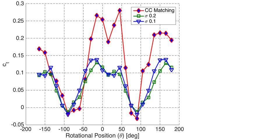
Figure 5. Tangential coefficient using solidity matching ( of 0.1 to
  of 0.2) during rotation of a CC-VAWT.

Figure 6. Momentum coefficient using solidity matching ( of 0.1 to
  of 0.2) during rotation of a CC-VAWT.

Figure 7. Coefficient of performance using solidity matching.
proached. The CC solidity matching method at a TSR of 4 using an initial solidity (σ0) of 0.1 that desired to match a solidity of 0.2 produced a Cp of 0.43 while the VAWT solidity (σm) of 0.2 produced 0.41. An Cp estimated overshoot of 4.5% occurred, most likely a numerical issue due to interpolations in the blade aerodynamic data. The test case examined demonstrates a CC-VAWT’s ability to change the tangential and power coefficient to match a desired solidity meaning that the CC solidity method has potential to control a VAWT’s performance without the need for constant jet momentum.
Further analysis of select solidity ranges for changing TSR was explored to evaluate the ability of the CC matching method to successfully operate at different TSRs. The Cp value was used as the performance benchmark during this analysis where a single initial solidity (σ0 of 0.1) was chosen, matching performance data for solidity ranges from 0.05 to 0.2. TSRs explored were from 1.5 to 10 ( : 0.66 to 0.1). Performance results of this analysis demonstrate that the solidity matching method using CC was capable of changing the Cp curve, shown in Figure 8, to ride the maximum Cp achievable. The CC-VAWT changed the performance curve to be wider (TSR range of 4.2 to 6) and have a higher peak (Cp of 0.33 to 0.42) for regions where power capture will be possible (Cp ≥ 0.1). In some cases, the CC matching method exceeded the maximum Cp that was desired for matching.
The momentum coefficient ( ) required by the CC solidity matching method for a range of TSR was examined based upon the previous maximum Cp simulation over a range of TSRs. An operation map of the required
  for a given TSR and rotational position was developed based on the simulation, shown for a single blade in Figure 9. Several things can be concluded from this map such as the rotational regions where CC is most used, TSRs where CC is less effective at matching, and requirements at the rotational azimuth locations.
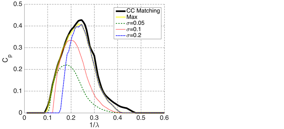
Figure 8. Solidity matching scheme predicted Cp at σ0 = 0.1.

Figure 9. Jet momentum coefficient required (initial solidity, σ = 0.1) to match best solidity.
CC is mostly used during the upwind portion (θ ± 45 deg) of rotation to control performance, which is where most VAWT’s experience the highest blade velocities and angles of attack. TSRs greater than 5 ( of 0.2) begin to experience a steep drop off in performance that the CC matching method is capable of controlling, but the ultimately the performance within this region is limited. Finally, when rotating through azimuth positions (θ ± 90 deg) the CC matching method continues to match performance by briefly using CC near maximum. A VAWT typically does not produce any and sometimes negative instantaneous power at the azimuth positions. Using the developed momentum map that seeks maximum performance at any TSR, a CC jet controller could then always operate as peak performance with the minimum required CC jet usage.
3. Conclusion
Dynamically using Circulation Control (CC) to improve performance of a VAWT was developed by varying CC jet momentum during rotation to change virtual or apparent solidity. The CC jet momentum for each blade was directly related to initial solidity and rotational position along with a desired solidity. CC was then used to modify each blade’s tangential force that in turn would match a desired performance or Cp. Many options are available to either choose a baseline or initial solidity that will produce the maximum performance, the widest operating TSR, or anywhere in between based on the desired amount of CC usage. Overall, the developed CC solidity matching method was capable of increasing performance of the CC-VAWT by matching solidity to the highest performing static solidity of a VAWT at each TSR (λ). Both the maximum Cp achievable and the width of the performance curve from an initial solidity were increased. The dynamic usage of CC reduced the jet momentum requirements significantly compared to the previous method of constant CC momentum and appears to be a viable method of efficiently and effectively utilizing CC for a VAWT.
Cite this paper
Wilhelm, J.P., Nix, A.C., Panther, C.C., Huebsch, W.W. and Smith, J.E. (2017) Dynamic Circulation Control for a Vertical Axis Wind Turbine using Virtual Solidity Matching. Smart Grid and Renewable Energy, 8, 99-113. https://doi.org/10.4236/sgre.2017.84007
References
- 1. Wiser, R. and Bolinger, M. (2007) Annual Report on U.S. Wind Power Installation, Cost, and Performance Trends. National Renewable Energy Laboratory Report, Denver.
- 2. Thresher, R., Robinson, M. and Veers, P. (2007) To Capture the Wind. IEEE Power & Energy Magazine, 7, 1540-7977. https://doi.org/10.1109/mpe.2007.906304
- 3. Pawsey, N. (2002) Development and Evaluation of Passive Variable-Pitch Vertical Axis Wind Turbines. PhD Dissertation, The University of New South Wales, Sydney.
- 4. Paraschivoiu, I., Trifu, O. and Saeed, F. (2009) H-Darrieus Wind Turbine with Blade Pitch Control. International Journal of Rotating Machinery, 2009, Article ID: 505343.
- 5. Wilhelm, J.P., Pertl, E.D., Pertl, F.A. and Smith, J.E. (2009) Performance Predictions of a Circulation Controlled-Vertical Axis Wind Turbine with Solidity Control. ASME 2009 3rd International Conference on Energy Sustainability collocated with the Heat Transfer and InterPACK09 Conferences, San Francisco, 19-23 July 2009, 1001-1007. https://doi.org/10.1115/es2009-90350
- 6. Wilhelm, J.P., Panther, C.C., Pertl, F.A. and Smith, J.E. (2009) Vortex Analytical Model of a Circulation Controlled Vertical Axis Wind Turbine. ASME 2009 3rd International Conference on Energy Sustainability Collocated with the Heat Transfer and InterPACK09 Conferences, San Francisco, 19-23 July 2009, 993-1000.
https://doi.org/10.1115/es2009-90348 - 7. Van Dam, C., Berg, D.E. and Johnson, S.J. (2008) Active Load Control Techniques for Wind Turbines. Sandia National Laboratories, Albuquerque.
https://doi.org/10.2172/943932 - 8. AslamBhutta, M.M., Hayat, N. Farooq, A.U., Ali, Z., Jamil, S.R. and Hussain, Z. (2012) Vertical Axis Wind Turbine—A Review of Various Configurations and Design Techniques. Renewable and Sustainable Energy Reviews, 16, 1926-1939.
- 9. Samsonov, V. and Baklushin, P. (1992) Comparison of Different Ways for VAWT Aerodynamic Control. Journal of Wind Engineering and Industrial Aerodynamics, 39, 427-433.
- 10. Lazauskas, L. (1992) Three Pitch Control Systems for Vertical Axis Wind Turbines Compared. Wind Engineering, 16, 269-282.
- 11. Hwang, I.S., Min, S.Y., Jeong, I.O., Lee, Y.H. and Kim, S.J. (2006) Efficiency Improvement of a New Vertical Axis Wind Turbine by Individual Active Control of Blade Motion. Smart Structures and Materials, 6173, 316-323.
- 12. Greenblatt, D., Schulman, M. and Ben-Harav, A. (2012) Vertical Axis Wind Turbine Performance Enhancement Using Plasma Actuators. Renewable Energy, 37, 345-354.
- 13. Owen, F.K. and Owen, A.K. (2006) Measurement and Analysis of Circulation Control Airfoils. Applications of Circulation Control Technology, Progress in Astronautics and Aeronautics, 214, 105-112.
- 14. Yen, J. and Ahmed, N.A. (2013) Enhancing Vertical Axis Wind Turbine by Dynamic Stall Control Using Synthetic Jets. Journal of Wind Engineering and Industrial Aerodynamics, 114, 12-17.
- 15. Panther, C.C., Williams, K.A., Wilhelm, J.P. and Smith, J.E. (2010) Experimental Testing of a Wind Tunnel Model for Use in a Vertical Axis Wind Turbine. Proceedings of the ASME 2010 International Mechanical Engineering Congress and Exposition. Vancouver, 12-18 November 2010, 153-161.
https://doi.org/10.1115/imece2010-38816 - 16. Shires, A. and Kourkoulis, V. (2013) Application of Circulation Controlled Blades for Vertical Axis Wind Turbines. Energies, 6, 3744-3763.
https://doi.org/10.3390/en6083744 - 17. Lubert, C. (2011) On Some Recent Applications of the Coanda Effect. International Journal of Acoustics and Vibration, 16, 144.
https://doi.org/10.20855/ijav.2011.16.3286 - 18. Abramson, J. (1984) Low-Speed Characteristics of a Circulation Control Airfoil with Aft Camber and a Spiral Trailing Edge. DTIC Document, Technical Report.
- 19. Jones, G.S. and Englar, R.J. (2003) Advances in Pneumatic-Controlled High-Lift Systems through Pulsed Blowing. AIAA 21st Applied Aerodynamics Conference, Orlando, 23-26 June 2003, 3411.
- 20. Englar, R.L.L. (1975) Circulation Control for High Lift and Drag Generation on STOL Aircraft. Journal of Aircraft, 12, 457-463.
https://doi.org/10.2514/3.59824 - 21. Haus, F. (1931) The Use of Slots for Increasing the Lift of Airplane Wings. Technical Memorandum, National Advisory Council for Aeronautics.
- 22. Englar, R.J. and Huson, G. (1984) Development of Advanced Circulation Control Wing High-Lift Airfoils. Journal of Aircraft, 21, 476-483.
https://doi.org/10.2514/3.44996 - 23. Kweder, J., Panther, C.C. and Smith, J.E. (2010) Applications of Circulation Control, Yesterday And Today. International Journal of Engineering, 4, 411-429.
- 24. Wolfe, W.P. (1978) Analysis of Test Results for the WVU Straight Bladed Darrieus wind Turbine. PhD Dissertation, West Virginia University, Morgantown.
- 25. McGrain, D., Angle, G.M., Wilhelm, J.P., Pertl, E.D. and Smith, J.E. (2009) Circulation Control Applied to Wind Turbines. ASME 2009 3rd International Conference on Energy Sustainability Collocated with the Heat Transfer and InterPACK09 Conferences, San Francisco, 19-23 July 2009, 905-910.
- 26. Graham, H.Z., Hubbell, M., Panther, C., Wilhelm, J.P., Angle, G.M. and Smith, J.E. (2009) Circulation Controlled Airfoil Analysis through 360 Degrees Angle of Attack. ASME 2009 3rd International Conference on Energy Sustainability collocated with the Heat Transfer and InterPACK09 Conferences, San Francisco, 19-23 July 2009, 571-577.
- 27. Tangler, J.L. (2000) The Evolution of Rotor and Blade Design. National Renewable Energy Laboratory, Golden.
- 28. Bianchi, F.D., De Battista, H. and Mantz, R.J. (2006) Wind Turbine Control Systems: Principles, Modelling and Gain Scheduling Design. Springer Science & Business Media, London.
- 29. Castelli, M.R., Englaro, A. and Benini, E. (2011) The Darrieus Wind Turbine: Proposal for a New Performance Prediction Model Based on CFD. Energy, 36, 4919- 4934.
https://doi.org/10.1016/j.energy.2011.05.036 - 30. Migliore, P.G. (1979) A Free-Vortex Model with Numerical Solution for the Unsteady Lifting Characteristics of Straight Bladed Darrieus Wind Turbines. PhD Dissertation, West Virginia University, Morgantown.
- 31. Walters, R.E., Fanucci, J., Loth, J., Ness, N. and Palmer, G. (1975) Innovative Wind Machines. Technical Report, 76, 33677.
- 32. Scheurich, F., Fletcher, T.M. and Brown, R.E. (2011) Simulating the Aerodynamic Performance and Wake Dynamics of a Vertical-Axis Wind Turbine. Wind Energy, 14, 159-177.
https://doi.org/10.1002/we.409 - 33. Wilhelm, J.P., Nawrocki, A., Hard, S. and Smith, J.E. (2010) Controller Design Methodology for a Circulation Controlled Vertical Axis Wind Turbine. Proceedings of 28th AIAA Applied Aerodynamics Conference, Chicago, 28 June-1 July 2010, 2010- 4405.
https://doi.org/10.2514/6.2010-4405 - 34. Roh, S.C. and Kang, S.H. (2013) Effects of a Blade Profile, the Reynolds Number, and the Solidity on the Performance of a Straight Bladed Vertical Axis Wind Turbine. Journal of Mechanical Science and Technology, 27, 3299-3307.
https://doi.org/10.1007/s12206-013-0852-x