Smart Grid and Renewable Energy
Vol.08 No.01(2017), Article ID:73003,30 pages
10.4236/sgre.2017.81001
PV Based Microgrid with Grid-Support Grid-Forming Inverter Control-(Simulation and Analysis)
Arangarajan Vinayagam1*, K. S. V. Swarna1, Sui Yang Khoo1, Aman Than Oo1, Alex Stojcevski2
1Faculty of Science, Engineering and Built Environment, Deakin University, Geelong, Australia
2Centre of Technology, RMIT University, Ho Chi Minh City, Vietnam

Copyright © 2017 by authors and Scientific Research Publishing Inc.
This work is licensed under the Creative Commons Attribution International License (CC BY 4.0).
http://creativecommons.org/licenses/by/4.0/


Received: November 16, 2016; Accepted: December 23, 2016; Published: December 26, 2016
ABSTRACT
Microgrid (MG) is a small entity of electrical network which comprises of various Distributed Generation (DG) sources, storage devices, and group of loads in various classes. MG provides reliable and secure energy supply to the critical loads of communities while operating either in on-grid or off-grid mode. In this study, a coordinated power management control strategy for a typical low voltage (LV) MG network with integration of solar Photovoltaic (PV) and storage facility has been developed and analysed in Matlab-Simu- link software environment at various modes (on-grid, off-grid, and on-grid to off-grid transition) of MG operation. Solar PV and battery power inverters are considered as grid-support grid-forming (GsGfm) Voltage Source Inverter (VSI) with the implementation of modified droop and virtual output impedance control strategies. Proposed control strategy supports coordinated control operation between PV units and battery storage, equal power sharing among the DG sources, and smooth MG mode transition with regulation of voltage and frequency level in MG network. In addition, voltage and current THD level were analysed and verified as per the standard of AS4777.
Keywords:
Microgrid, Distributed Generation, Power Management, Power Sharing, Grid-Support Grid-Forming Inverter

1. Introduction
MG is a small entity of electrical network which comprises of multiple DG sources, energy storage devices, and group of loads, which can be operated in either on-grid (grid connected) or off-grid (islanded) mode of operation [1] [2] . In either mode of MG operation, maintaining energy balance is necessary to get the better regulation of voltage and frequency level in MG network. In case that any mismatch between the generation and load demand causes deviation in the voltage and frequency level which creates a negative influence on the quality of energy supply, thus affecting the performance of sensitive loads connected in the MG network. In on-grid mode, regulation of voltage and frequency level in MG network can be supported by the utility grid. However, in off-grid mode, all the DG sources should be responsible for ensuring power balance and also regulation of voltage and frequency level in MG network through active coordinated power management and power sharing control strategies [3] . Due to the low environment impact, less maintenance, and high reliability, Solar PV is considered as one of the main Renewable Energy (RE) sources for MG applications. Due to the intermittent nature of PV power, a battery storage can be used to smooth out PV power variation and maintain the power balance in PV based MG network [4] [5] [6] .
1.1. Control Configuration of Power Inverters in the MG Network
Voltage Source Inverter (VSI) is widely used in the MG network for applications involving the DG sources like: solar PV, battery storage, fuel cell, etc. Control configuration of power inverters in the MG network can be classified into three types based on their operation role, namely: grid-feeding, grid-forming, and grid-supporting power inverter. Grid-supporting power inverter can be further classified as grid-support grid-feeding (GsGfd) and grid-support grid-forming (GsGfm) type [7] [8] [9] . As per the classification, each type of power inverter control details is given in Table 1.
The GsGfd type inverter needs at least one voltage source power inverter to be online for regulating voltage and frequency level in network, otherwise this type of inverter control is required to switch over to grid-forming or GsGfm control while MG transits to islanding mode. On the other hand, by using GsGfm type, a rapid mode switching between current and voltage control can be eliminated while either generators transition being on and off or MG switching from on-grid to off-grid [7] [8] [9] . Hence the GsGfm control enables the power inverter to operate in either mode of MG operation without changing its control configuration.

Table 1. Classification of power inverters.
P and Q are active and reactive power; V and f are voltage and frequency; ref is reference value.
In the proposed MG model, interfacing power inverter for both the PV and battery storage has been considered as GsGfm type.
1.2. Power Management Control in the MG Network
Many types of power management control strategies for the MG network could be found in the literature. Y. Wang et al. developed a model predictive algorithm that enables faster dynamic response in power management during both on-grid and off-grid mode of MG operation. According to them, during on-grid, solar PV and battery storage inverters are working in current control mode (CCM) as grid feeding type and during off-grid mode, battery storage inverter is working in voltage control mode (VCM) as grid forming type and PV inverter is working in CCM [10] . Hisham et al. implemented multi-loop and multi-segment adaptive droop control strategies for a PV/battery hybrid unit in islanded mode of MG network, at the same time; implemented a battery storage control which ensures better regulation of voltage and frequency level [11] . Dan Wu proposed a control algorithm that follows as per the bus frequency signal to achieve power management in decentralized manner for islanded MG. In his work, PV inverter is considered as grid feeding (CCM) type and battery storage inverter is considered as a grid forming (VCM) type which compensates power imbalance in the islanded MG network [4] . Similar type of arrangement is used by Ashishkumar in his study, with the virtual droop control (VDC) and unit commitment algorithm being the only difference in the MG network. Compared to conventional droop technique, VDC strategy ensures better voltage and frequency regulation in the MG network [12] . Yun Su applied control strategies for voltage/frequency regulation and battery storage of the stand-alone MG which has low system inertia or weak network with penetration of RE sources in higher level. Local voltage fluctuations caused by the intermittent output power of RE sources, solved through the implementation of Q/P droop control in reactive power controller of renewable generation system [13] . As per Ling, implementation of coordinated power control strategies for battery (CCM while MG is in grid connected mode whereas on VCM which follows as per V-f control strategy during autonomous mode) and PV inverters (CCM which follows the implementation of dual loop d-q control algorithm in P-Q control strategy during both mode of MG operation) ensures the power balance in MG network during varying load and varying solar irradiance conditions [14] .
In summary, various types of control strategies were developed and implemented to ensure better power management and coordinated operation of DG sources in PV based MG network. Most of the analysis in PV based MG network, considered inverter of PV source as grid-feeding type which allows to operate in P-Q control (CCM) during on-grid and off-grid mode of MG operation, and battery inverter allows to operate in V-f control (VCM) during islanded mode of MG operation. Also the control strategies for VSI have been developed using either grid-feeding or grid-forming type in PV based MG network.
Hence, in this study, VSI of solar PV has been allowed to operate in maximum power generation with P-Q control during grid connected mode of MG, whereas in islanded mode, the inverters of PV source has been allowed to curtail its generated power according to load conditions, which follows the same operating concept of PV inverters in CERTS MG network [15] . Also VSI of solar PV and battery storage in the proposed MG model has been implemented with the GsGfm type which is having special features like; elimination of rapid mode switching between current and voltage control while either generators transition on and off or able to work in either mode of MG operation without changing of its control configuration.
1.3. Power Sharing Control in the MG Network
Conventional P-f and Q-V droop control is more suitable for power sharing among DG sources in highly inductive nature of distribution network whereas a modified or reverse P-V and Q-f droop power sharing control is applicable for VSI of DG sources in MG power system with resistive nature of LV network [16] [17] . This type of modified or reverse droop control for MG power system with resistive nature of LV network is the subject of interest to this study. Several research works on droop control methods for DG sources integrated in LV network of MG power system have been reported by various researchers and is highlighted below.
Joseph et al. proposed a novel modified droop controller using resistive output impedance for parallel connected single phase inverters in islanded LV network that improves steady state and dynamic response of the system. It enables better power sharing with low sensitivity while line impedances are in unbalanced condition and also ensures automatic harmonic current sharing along with better power sharing while presence of linear and non-linear loads in MG network [18] . Similarly, Xiao et al. proposed hybrid control architecture for parallel connected inverters of DG sources in islanded LV network of MG using virtual resistor control scheme ensures balanced power sharing among DG sources as well as improved steady state and dynamic performance [17] . According to Tine et al., P-V droop control with provision of automatic power sharing technique for inverters of DG sources, connected in LV network of MG power system improves the efficiency of system network and reduces line losses by means of allowing DG source which is near to the load center (electrically) takes larger part in power sharing as compared to DG source in far away. In islanded mode of MG operation, line losses are less while DG sources with P-V droop automatic power sharing control strategy as compared to DG sources with P-f droop and virtual output impedance control strategy [19] . Jianjun Su et al. implemented integrated droop control strategy with virtual impedance for inverters of energy storage device (ESD) in LV network of MG power system. This proposed control strategy keeps output voltage of inverters in steady state with improved sharing of reactive power flow and provides better decoupling of active (P) and reactive power (Q) in MG network that ensures better power sharing among DG sources and better stability of the system [20] . Ping et al. studied the coupling effect and dynamic instability of active and reactive power control in resistive nature of LV network by implementing novel virtual impedance which is composed of virtual negative resistor (VNR) and virtual inductor integrated into the MG power system. This enhances the stability of grid connected inverter control during the case of any drift in line parameters [21] .
In a nutshell, based on the literature review performed, modified droop with implementation of virtual impedance output control strategies were commonly used in different methods of approach for inverter control of DG sources in LV network of MG, in order to get better power sharing among DG sources with decoupling of active and reactive power, to improve the dynamic stability of system in case of any transient conditions, sharing of harmonic currents while presence of non-linear load in MG network, etc. Most of the research works have been focused on islanded MG network and only few research works have been reported on both the grid connected and islanded mode of MG operation. Likewise, control methods considered were either grid-feeding (CCM) or grid- forming (VCM) type inverters of DG sources. According to the authors, the motivation behind the use of GsGfm type inverter in LV network of MG was due to the lack of in-depth research works on the topic.
1.4. Summary of the Findings
Based on the research work of the previous researchers [4] [10] [11] [12] [17] [18] [19] [20] , it can be observed that various type of control strategies have been proposed for power management and power sharing of the typical MG model with PV and battery storage for the LV network. VSI of PV based MG network was allowed to operate in P-Q control (CCM) during on-grid and off-grid mode of MG operation whereas the battery storage was allowed to operate in V-f control (VCM) during islanded mode of MG operation. Similarly, the control strategies for VSI have been developed using either grid-feeding or grid-forming type in PV based MG network. Likewise, a number of control methods were used by researchers to ensure better power sharing among the DG sources with decoupling of active and reactive power, to improve the dynamic stability of system in case of any transient conditions, sharing of harmonic currents while presence of non-linear load in MG network, etc. The number of research articles on the GsGfm type inverter in LV network of the PV based MG network is limited.
1.5. Outline
In this study, solar PV and battery storage based MG model have been developed in Simulink-Matlab software environment. Modified droop and virtual output impedance control for GsGfm inverters have been proposed in LV network of MG model. Effectiveness of implemented control strategies was verified through MG model simulation and ensured better regulation of voltage and frequency level, power sharing among DG sources, and level of harmonic distortions in the MG network while MG was running in on-grid, off-grid, and on-grid to off-grid transition mode. This paper is organized as follows: Section 2 describes the configuration MG model; Section 3 presents the details of power converters and their control configuration; Section 4 describes the power management control strategies for on-grid and off-grid mode of MG operation; Section 5 demonstrates the type of analysis and results discussion; and Section 6 gives the conclusion of model analysis with information of future research work.
2. Typical MG Model Configuration
The configuration of typical AC MG network model which is operating at voltage and frequency level of 400 V and 50 Hz, is shown in Figure 1. The specification details of AC equipment, DC equipment, and LV load/feeder which includes in MG network are given in Table 2, Table 3, and Table 4 respectively.
2.1. Solar PV Unit
In this proposed MG model, Solar PV unit includes two stage of power converters; DC-DC boost converter and DC-AC Voltage Source Inverter (VSI). A typical

Figure 1. Typical configuration of MG model.
Table 2. Details of DC equipment.
Table 3. Details of AC equipment.
Table 4. Details of LV load and feeder.
solar PV unit has been considered with maximum power generation capacity of around 210 kWat standard test condition (STC). Each PV module open circuit voltage (VOC) and short circuit current (ISC) has been considered around 64.2 V and 5.36 Amps respectively. Maximum power versus voltage (P-V) and PV current versus voltage (I-V) characteristics curve of proposed solar PV unit at different solar irradiance conditions are shown in Figure 2 and Figure 3 respectively.
DC Power Converter of Solar PV
DC-DC boost power converter is widely used for solar PV unit which amplifies and regulates the PV array voltage into specified level along with extraction of maximum power from PV array as per maximum power point tracking (MPPT) control algorithm. Implementation of MPPT control algorithm in DC converter varies duty cycle of converter according to maximum power condition [22] [23] . In this proposed MG model. Perturb and observe (PO) MPPT control algorithm has been implemented for DC converter of PV unit which boosts up PV array voltage (280 V) into 500 V as nominal level at inverter input.

Figure 2. PV Power versus PV voltage (P-V characteristics).

Figure 3. PV current versus PV voltage (I-V characteristics).
2.2. Battery Storage
Battery storage plays a major role in PV based MG network, where it smoothes out power variation of solar PV and maintain power balance between generation and consumption. It ensures better voltage and frequency regulation, power support for critical loads in MG network while stand-alone condition. Also it improves power quality, stability of distribution network and fulfils the various demand side management functions like; load levelling, peak shaving, etc. [4] [5] [10] [24] . In this study, a storage unit has been considered as parameterized generic model of lead acid battery which is available in Matlab-Simulink. Operating voltage (V) and Ampere-hour (Ah) capacity of lead acid battery unit has been considered around 300 V and 340 Ah respectively.
DC Power Converter of Battery Storage
DC buck-boost converter which is called as bidirectional converter is widely used to interface battery storage unit in DC side. DC bidirectional converter mainly consists of two IGBT switches out of that one switch allows battery operation in buck mode while charging and other switch allows in boost mode while discharging condition [25] [26] . In this proposed MG model, bidirectional dc converter of battery unit has been considered to operate in the voltage level of around 300 V in buck side to 500 V in boost side. In this study, central power management determines the charge and discharge operation of battery according to the following conditions; availability of PV power generation/load condition in MG network, SOC level of battery. In order to avoid battery from overcharge and under discharge condition, the SOC control in power management allows to operate the battery within safe SOC operating range (30% to 80%).
2.3. Control Configuration of VSI (GsGfm Type)
A simplified GsGfm inverter which is shown in Figure 4(a) includes droop control, voltage control and an ideal AC voltage source in series with a link impedance (Z). GsGfm inverter acts as a droop-controlled AC voltage source, where it provides voltage and frequency references according to the measured active (P) and reactive (Q) power in MG network. This type of converter regulates voltage and frequency in MG network during on-grid and off-grid mode of MG operation [7] [8] [9] . Figure 4(b) shows the overall control configuration of VSI which is used for PV units and battery storage in this proposed MG model. The control configuration of VSI mainly includes power calculation block, droop control, voltage control loop with inclusion of virtual impedance control, and current control loop. Detailed configuration of power calculation block/droop control and voltage/current control loop are shown in Figure 5 and Figure 6 respectively. Control configuration of VSI is explained in this section as below.
 (a)
(a) (b)
(b)
Figure 4. (a) Simplified GsGfm type VSI; (b) Overall control configuration of VSI.

Figure 5. Configuration of power calculation block and droop control.

Figure 6. Configuration of voltage and current control.
2.3.1. Power Calculation Block
Inverter output three phase voltage (Vabc) and current (Iabc) which is there in stationary (abc) coordinate form can be transformed into rotating direct-quadrature (d-q) system by means of Park transformation. The d-q components of voltage and current are considered as input signals for power calculation block where the active (P) and reactive (Q) power can be calculated as per the power Equations (1) and (2) [3] [27] [28] .
 (1)
(1)
 (2)
(2)
where vd, id are the d-axis voltage and current components; vq, iq are the q-axis voltage and current components.
In general on the basis of current flow from DC to AC side in an equivalent circuit of inverter, the voltage balance equation in d-q frame can be expressed as per the Equation (3) [28] [29] [30] .
 (3)
(3)
where Ud, Uq are the inverter output voltage reference signals; Vd, Vq are the inverter output voltage components; id, iq are the inverter output current components; R and L are the resistance and inductance between inverter and AC network; ω is the network angular frequency (rad/sec).
2.3.2. Droop Control
On contrary to inductive nature of HV network, in low voltage (LV) network where the line impedance is in resistive nature that the active power (P) can be controlled by the voltage magnitude (V) and reactive power (Q) can be regulated by controlling power angle (δ) of network [8] [17] [18] . Active (P) and reactive (Q) power flow in LV network can be expressed as per Equations (4) and (5) respectively.
 (4)
(4)
 (5)
(5)
where V1 is inverter output voltage magnitude; V2 is the voltage magnitude of PCC network; X is the line impedance (resistance); and δ is the power angle.
Considering the expression of power flow Equations in (4) and (5), power droop control strategies in LV network can be expressed as per in Equations (6) and (7) respectively. In contrary to conventional P-f and Q-V droop control, modified P-V and Q-f droop control which is known as opposite droop control is commonly used for LV network [8] [16] [17] [31] .
 (6)
(6)
 (7)
(7)
 (8)
(8)
 (9)
(9)
where P and Q are the actual active and reactive power; P* and Q* are the nominal active and reactive power; ωn and Vn are the nominal value of angular frequency (rad/sec) and voltage amplitude (v) in network; ω* and V* are the input reference of angular frequency and voltage magnitude; Kp and Kq are the droop coefficients of active and reactive power; ∆ωmax and ∆Vmax are the maximum angular frequency and voltage deviations; Pmax and Qmax are the maximum real and reactive power delivered by the power converter.
2.3.3. Virtual Impedance Control Loop
Implementation of virtual impedance control loop at output of the power inverter enhances the decoupling relation between active (P) and reactive (Q) power and improves power sharing accuracy. Implementation of resistive output impedance (RD) in control loop, droops the output voltage reference in proportion to the inverter output current. Voltage drop across the virtual impedance control loop can be expressed as per Equation (10) [8] [17] [18] [31] [32] [33] . In this study, virtual resistor has been implemented in virtual impedance control loop in order to maintain large R/X ratio and improves power sharing accuracy.
 (10)
(10)
where Vo is the voltage drop across virtual impedance; RD is the virtual impedance (resistor); and id is the inverter output current.
2.3.4. Voltage and Current Control Loop
Proportional-Integral (PI) based voltage control loop generates output d-q reference current (idref, iqref) signals while comparing modified voltage reference signal with actual d-q voltage components (Vd, Vq) at input side. Modified voltage reference signal is a new voltage reference signal after subtraction of virtual impedance voltage drop from the original voltage reference signal, generated by the droop controller. By regulating id and iq current components at the output of inverter that the active (P) and reactive (Q) power can be controlled. As per control configuration of voltage control loop which is shown in Figure 6, modified voltage reference (Vref (M)) signal can be expressed as per Equation (11) and the d-q components of reference current (idref, iqref) can be expressed as per in Equations (12) and (13) respectively.
 (11)
(11)
 (12)
(12)
 (13)
(13)
where E** is the voltage reference signal; Vref(M) is the modified voltage reference signal; Vd and Vq are the d-axis and q-axis actual voltage component; Id and Id-ref are the d-axis actual and reference inverter current component; Iq and Iq-ref are the q-axis actual and reference inverter current component; Vo is the voltage drop across virtual impedance; Kp and Ki is the proportional and integrator gain of PI controller.
PI based current control loop generates output voltage signal (Ud, Uq) in d-q form which is used as reference voltage for pulse width modulation (PWM) block of inverter. In this concept, in order to improve the performance of PI controller, decouple the d-q components of voltage and current, and improve the dynamic response of cascade control, the cross coupling term and the voltage feed forward facility are usually employed [34] [35] . With reference to voltage balance Equation (5), inverter voltage equations in d-q form can be written as per expressions in (14) and (15) respectively [28] [29] [30] .
 (14)
(14)
 (15)
(15)
Thus from the above Equations (14) and (15), in order to control id and iq independently that the coupled term can be decoupled through implementation of current feed forward compensation technique in inverter current control loop. In this study, in order to enhance the stability of inverter current controller that the decoupling operation through current feed forward compensation has been adopted by considering inverter reference currents (idref, iqref) instead of output measured currents (id, iq) [8] [36] . As per the control configuration of current control loop with inclusion of feed forward system which is shown in Figure 6, the inverter output voltage signals of current control loop can be expressed as per Equation (16).
 (16)
(16)
 ;
; ;
;
where Ud and Uq are the output voltage signal in d-q form; ω is the angular frequency of network; L is the inductance between inverter and PCC network; Vd is the d-axis voltage component; Vq is the q-axis voltage component; Id and Id-ref are the d-axis actual and reference current component; Iq and Iq-ref are the q-axis actual and reference current component; Kp and Ki is the proportional and integrator gain of PI controller.
Current control loop output reference signals (Ud, Uq) represented in d-q form can be transformed into voltage reference signal in abc-frame (Uabc) through reverse parks transformation. In order to generate sine wave form at appropriate reference level, the final voltage reference signal (Uabc) needs to pass through the PWM block. Based on the voltage reference signal (Uabc) and measured phase angle of AC network, the PWM block generates pulsing signal for Inverter bridge that ensures desired output voltage vector with less harmonics [36] [37] [38] . Main parameters of VSI control, used in the proposed MG system is given in Table 5.
Details of Power management control strategies, developed for on-grid and off-grid mode of MG operation has been discussed in the following section.
3. Power Management Control Strategies
In this study, for proposed PV based MG network, power management control strategies have been developed for on-grid and off-grid mode of operation.
3.1. On-Grid Power Management
On-grid power management includes PV power management, battery power (active (P) and reactive (Q) power) management with inclusion of battery SOC control, which is explained in detail as below.
3.1.1. PV Power Management (On-Grid)
During on-grid mode, grid source act as a main power source which buffers any
Table 5. Inverter control and system parameters.
deficit or excess power generation in MG network. Both PV units were allowed to operate at maximum power generation like P-Q control method. Active power set (Pset) of each PV unit was assigned to be 100% of its nominal power capacity (210 kW) irrespective of active power demand (PL) and reactive power set (Qset) of each PV unit was assigned to be 40% of total reactive power demand (QL) in MG network.
3.1.2. Battery Active (P) and Reactive (Q) Power Management (On-Grid)
Control strategies of active (P) and reactive (Q) power management which is shown in Figure 7 includes charge/discharge, and SOC control of battery. Active power charge control allows the battery to charge as per assigned power set (Pset) on the basis of following conditions; if power difference between both PV units and total active power load in MG network was equal/more than 10 kW, (or) if power export to grid network was equal/more than 5 kW, (and) solar irradiance level was equal/more than 1000 (Watts/m2).
Similarly, based on the solar irradiance level, the battery discharge control strategies were developed in two levels. In the first level, battery was allowed to discharge as per assigned power set (Pset) if the solar irradiance level was equal/more than 990 Watts/m2. In second level, if solar irradiance level reaches below the first level (990 Watts/m2), the battery discharge power control follows a look-up table curve which is shown in Figure 8. As per this curve, battery discharge control allows the battery to discharge accordingly during the solar

Figure 7. Power management control of battery (on-grid).

Figure 8. Look-up table for battery discharge (2nd level).
irradiance of PV unit varies as below 990 Watts/m2. This is to ensure smooth-out or compensating the power variation of PV in case of any disturbance in solar irradiance condition.
Reactive power management control enables the battery to discharge as per assigned reactive power set (Qset) with the following conditions; if sum of the reactive power contribution from both the PV units were more than 26 kVAR, (or) reactive power import from grid network was more than 10 kVAR, (and) total reactive power demand was more than 45 kVAR in MG network.
SOC control ensures safe operation of battery by allowing battery to operate between safe ranges (30% to 80%) of SOC level. In order to avoid over charge and under discharge condition of battery, SOC control stops battery from charging while SOC reaches equal/above 80% (maximum), similarly it stops from discharging, while SOC reaches equal/below 30% (minimum).
3.2. Off-Grid Power Management
In off-grid mode, inverters of PV units were operating as voltage source which provides active and reactive power support according to the voltage and frequency level in MG network. Battery storage provides active and reactive power support according to power generation level of PV and power demand in MG network. Therefore, power management in off-grid mainly involves the battery power management with inclusion of SOC control. In addition, load management control strategy was implemented for safe and reliable operation of PV based MG.
3.2.1. Battery Active (P) and Reactive (Q) Power Management (Off-Grid)
Control configuration of battery active (P) and reactive (Q) power management which includes SOC control and load management, as shown in Figure 9. In off-grid mode, active power management control initiates battery control into charging mode if the total active power (PL) in MG network was less than the maximum power capacity of both PV units. In addition, charge control continues to allow battery to charging with the following conditions; if PV unit output power generation was less than 95% (200 kW) of its nominal power capacity and solar irradiance level should be equal/more than 1000 Watts/m2. Similarly, if

Figure 9. Battery Power Management with inclusion of Load Management (off-grid).
both PV units were in maximum power generation (above 400 kW) and total active power load in MG network was more than both the PV capacities, the battery active power discharge control allows battery to discharge in the appropriate level.
Similarly, if reactive power contribution of both PV units were less than total reactive power load (QL) in MG network, the reactive power management control allows battery to discharge reactive power in the appropriate level.
3.2.2. SOC Control and Load Power Management (Off-Grid)
SOC control behavior was same like as in on-grid power management, stops battery from charging while SOC reaches equal/above the 80% and stops from discharging while SOC reaches equal/below 30%. In addition, whenever SOC level reaches into equal/below 30% and each PV unit power generation was more than 90% (190 kW) of its nominal power capacity, the load management control strategy switch off feeder-1 loads which were considered as non-critical loads.
In this proposed MG model, power management control strategies was developed and implemented in order to get better power balance and coordinated control operation between PV and battery storage while MG was operating in both on-grid and off-grid mode. In addition, better voltage and frequency regulation and power sharing among DG sources in MG network was guaranteed by means of implementing modified droop with virtual output impedance control for GsGfm VSI of PV and battery storage. Effectiveness of control strategies were verified through the model simulation in Matlab-Simulink while varying solar irradiance of PV and varying load conditions in LV network of MG power system. Through this study, regulation in voltage and frequency level, coordinated power sharing among PV units and battery storage, and harmonic distortions in MG network were analyzed in the following MG modes like: on-grid, off-grid, and on-grid to off-grid transition mode. Methodology and outcome results from this analysis are discussed in detail in the following section.
4. Model Analysis and Results
In order to verify effectiveness of the control strategies in the proposed MG model network, detailed simulation analysis were carried out at different operation of MG modes like; on-grid, off-grid, and on-grid to off-grid transition.
4.1. On-Grid Mode
In on-grid mode, both PV units were allowed to operate in P-Q control mode and battery storage was allowed to charge and discharge according to availability of PV power generation with respect to power demand in MG network, solar irradiance level, and amount of power flow to the grid network. During this analysis, voltage and frequency level in MG network, power sharing among PV units, battery storage, and grid source were analyzed with varying solar irradiance and load conditions.
4.1.1. Varying Load
During this analysis, load variation was set to 2 stages in the MG network.
・ 1st stage (2 sec), load was increased from 300 kW/30 kVAR into 370 kW/40 kVAR and
・ 2nd stage (4 sec), it was further increased to 450 kW/50 kVAR.
4.1.2. Varying Solar Irradiance
・ PV1 power was varied from 210 kW to 150 kW (2.5 sec to 3.5 sec) due to variation of solar irradiance from maximum (1000 watts/m2) to minimum level (745 watts/m2).
4.1.3. Discussion
The active (P) and reactive (Q) power contribution from PV units, battery storage, and grid source, observed during the varying load and varying solar irradiance of PV1 in the MG network is shown in Figure 10.
Throughout the on-grid analysis mode, the active power management control ensures;
・ Active power generation for both PV1 and PV2 to be around 210 kW, with the exception of PV1 decreasing from 210 kW during the variation of solar irradiance condition (as shown results from Figure 10).
・ Battery storage to charge to a maximum of around 50 kW during excessive PV power generation/low demand and to discharge to a maximum of around

Figure 10. Active (P) and Reactive (Q) power sharing among sources and load (on-grid).
50 kW when the total power demand exceeds maximum power generation of both PV units in the network. In order to avoid excessive power import from the grid network, the active power management control enables the battery to discharge to a maximum of 50 kW when PV1 power generation was less during the solar variation.
Similarly, reactive power management control ensures:
・ Reactive power contribution from both PV units according to the load variation in each stage which reaches a maximum of 20 kVAR from each PV unit while the total reactive power demand was at the maximum level of around 50 kVAR in the MG network.
・ Contribution of reactive power support from the battery to be around 6 kVAR when the total reactive power demand was exceeding 45 kVAR in the MG network. However during this analysis, a small variation (10 to 15 kVAR) in reactive power level of PV1 and corresponding variation (−25 to −30 kVAR) effect in grid side was observed during the varying solar irradiance condition.
During the on-grid mode of MG operation, the regulation of voltage and frequency level in MG network was mainly supported by the grid source. Furthermore, as shown in Table 6 and Figure 11, it can be concluded that only a small
Table 6. Voltage and frequency variation (on-grid).

Figure 11. Voltage and Frequency level (on-grid).
variation in voltage and frequency level was observed during the varying solar irradiance and load conditions in the MG network. A slight variation in frequency level of around 49.99 Hz to 50.02 Hz and 49.99 to 50.01 Hz was observed while varying solar and load condition. Similarly, a slight variation in voltage level of around 1.01 to 1.02 voltage (per unit) and 1.01 to 0.99 voltage (per unit) was observed during solar and load varying conditions.
Thus from the results of on-grid analysis (Figure 10 and Figure 11), it was observed that the power balance and coordinated control operation in MG network were achieved through the implementation of power management control for PV units and battery storage. Similarly, with the support of utility grid source and proposed inverter control, the regulation of voltage and frequency level was ensured in the MG network.
4.2. Off-Grid Mode
In off-grid mode, both PV units were sharing their power generation according to voltage and frequency level in MG network. According to availability of PV power generation and total load in MG network, the battery storage was allowed to charge and discharge accordingly by means of battery power management control strategies. During this analysis, power sharing among PV units and battery storage, voltage and frequency regulation in MG network were analyzed while varying load condition. In addition, control operation of load management was analyzed while SOC condition of battery was equal/below 30% level.
4.2.1. Varying Load
Variation of load in MG network was initiated in each stage as follows:
・ At first stage, total load was increased from 340 kW/40 kVAR to 460 kW/60 kVAR (1.5 sec),
・ At second stage, total load was reduced to 340 kW/40 kVAR (3.5 sec), and
・ At third stage, total load was increased back to 460 kW/60 kVAR (4.5 sec).
4.2.2. Discussion
Based on the results obtained from the off-grid mode of analysis as shown in Figure 12, it can be observed that
・ Initially, contribution of active power (P) by each PV unit was around 180 kW according to the 1st stage of load and their power contribution was increased to further level of around 195 kW once charging of the battery was initiated by the battery power management.
・ Output power contribution of both the PV units were at maximum level (210 kW each) and discharging of battery in appropriate level was initiated by its power management control, when the total active power demand in the network was high. Maximum storing of active power (P) by the battery was found to be 45 kW and the maximum contribution was around 42 kW respectively, when the total active power demand was low and high in MG network.

Figure 12. Active (P) and reactive (Q) power sharing among sources and load (off-grid).
・ Contribution of reactive power from each PV unit was 18 kVAR and 25 kVAR respectively during the low and high reactive power demand in the MG network. Also the battery reactive power management control allowed the battery to discharge around 3 kVAR and 9 kVAR respectively during the low and high reactive power demand in MG network.
・ Variation in reactive power level from each PV unit was observed around 5 kVAR (13 to 18 kVAR) during the second stage of load varying condition.
・ Power variation from the battery side was observed as more than 5 kVAR during the load varying conditions in all three stages.
As per the analysis of voltage and frequency level in MG network which is shown in Table 7 and Figure 13, variation in frequency and voltage level was observed while varying load in all three stages. Variation in frequency level at first, second, and third stage of load variation was observed around 50.1 to 49.8 Hz, 50.1 to 50.4 Hz, and 50 to 49.6 Hz respectively. Similarly, voltage variation during first and third stage of load variation was observed around 1.1 to 0.85 voltage (per unit), and at second stage was around 1 to 1.3 voltage (per unit) respectively.
Table 7. Voltage and frequency variation (off-grid).

Figure 13. Voltage and frequency level (off-grid).
4.2.3. Minimum SOC Level
As per SOC control logics in power management, behavior of MG power system in particular off-grid mode operation was analyzed while SOC of battery reaches equal/below 30% level. In addition, control behavior of load management was analyzed in order to ensure reliability of the system and safe operation of PV inverters while MG was operating in off-grid mode.
When the SOC limit reaches a minimum level of 30% or below it (as per results, shown in Figure 14:
・ SOC control of battery stops the battery from discharging.
・ LV feeder-1 loads were switched off by the load management control when total power demand was high i.e. above 380 kW, which exceeds 90% nominal power (190 kW) of each PV unit.
・ Once the feeder-1 loads were switched off, the power contribution from each PV unit was decreased from 210 kW to 195 kW according to the new load condition. This was done to ensure safe operation of both PV units without overloading it and also to improve reliability of the MG power system.
From the off-grid mode analysis, it was clear that an effective power sharing among PV units and better regulation of voltage and frequency level in MG

Figure 14. Analysis of SOC and load management control at minimum SOC level.
network were ensured by means of implemented modified droop with virtual impedance control in PV inverters. In addition, better power balance in MG network was ensured by means of implemented power management control of battery, based on the total power demand and availability of PV power generation in MG network. Also, safe operation of battery was ensured by SOC control when the battery SOC reached 30% (minimum level). Similarly, reliable operation of MG power system and safe operation of PV units were ensured by means of implemented load management control in the islanded (off-grid) MG network.
However, a considerable amount of variation in reactive power level was observed from both the PV units and battery storage during the varying load condition in islanded MG network. Voltage and frequency variation was high in the off-grid compared to the on-grid mode during the varying load conditions in MG network. This is due to the lack of power inertia availability in islanded MG network and also influence of PI based controller performance during transient conditions in MG network [9] [39] .
4.3. On-Grid to Off-Grid Transition Mode
Because of using Grid-support Grid-form (GsGfm) VSI for PV units and battery storage, a smooth transition was ensured during the on-grid to off grid mode. In this section, power variation/sharing among PV units and battery, variation in voltage and frequency level were analyzed at that time of transition from on-grid to off grid mode.
4.3.1. Transition (On-Grid to Off-Grid)
At 2 sec, breaker was opened at PCC and MG was in transition from on-grid to off-grid mode.
4.3.2. Discussion
Results from this analysis as shown in Figure 15, includes active (P) and reactive (Q) power sharing among sources/load along with voltage and frequency level in MG network.
・ Before the transition mode, each PV unit power contribution was around 210 kW/5 kVAR and the battery discharge was around 27 kW/0 kVAR. At the same time, total power demand in MG network was around 445 kW/45 kVAR and power import from grid side was around 5 kW/30 kVAR.
・ During transition (2 sec), both PV units and battery storage continued to operate in smooth manner with no variation in power level observed from both the PV units and battery storage.
・ Due to the opening of breaker at PCC and loss of power support from grid side, contribution of power from both PV units and battery storage was as follows; each PV unit active power contribution was same (210 kW) and reactive power contribution increased from 9 kVAR to 20 kVAR. Similarly, active power contribution from battery was increased from 27 kW to 32 kW and the reactive power increased from 0 kVAR to 10 kVAR.

Figure 15. Analysis of power flow and voltage/frequency level during transition (on-grid to off-grid).
In addition as shown in Figure 15 and Table 8, a small variation in voltage level was observed around 0.98 to 1.03 voltage (per unit) and changes in frequency level was observed around 50 to 50.20 Hz. However this variation was small as compared to variation level while varying load condition in off-grid mode.
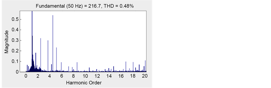
4.4. Total Harmonic Distortion (THD) Analysis
In this study, current and voltage THD were analysed in common bus of the MG network and the obtained harmonics level were compared as per the AS 4777 standard level. As per the AS 4777 standard maximum limit of current harmonics (up to 50th order) injection from integrated PV inverter should be less than 5% [40] and compatibility level of voltage THD in LV network should be less than 8% [41] .
The voltage THD and current THD were found to be 0.48% and 3.93% respectively in the common bus of MG network (Figure 16(a) and Figure 16(b)).
Table 8. Voltage and frequency variation (on-grid to off-grid).
 (a)
(a) (b)
(b)
Figure 16. (a) Voltage THD; (b) Current THD.
Thus from the results obtained, it can be concluded that the voltage and current THD level in common bus of MG network were found to be minimum and within the tolerance level as per AS4777 standard.
5. Conclusions
In this study, a typical MG model was built in Matlab-Simulink software and the following factors were analyzed: 1) power sharing among the DG sources; 2) power balance and coordinated operation between PV units and battery storage; 3) regulation of voltage and frequency level while the MG was operating in on- grid, off-grid, and on-grid to off-grid transition mode. Also, the current and voltage THD level was assessed in the common bus network of MG power system.
In on-grid mode, active (P) and reactive (Q) power contribution from PV units, battery storage, and grid source was ensured in coordinated way by means of implemented power control strategies in the MG network. Similarly, better regulation of voltage and frequency level in MG network was ensured mainly by grid source and additional support from the inverter control of PV units and battery storage. Only a small variation in voltage and frequency level was observed while varying solar and varying load conditions in MG network. Also, a small variation in reactive power level (5 kVAR) of PV1 and corresponding effect of reactive power variation in grid side was observed while varying solar irradiance of PV unit-1.
In the off-grid mode of analysis, factors such as power sharing, coordinated operation between PV units and battery storage, and regulation of voltage and frequency level were analysed while varying load in MG network. Based on the results obtained, power sharing between PV units and battery storage, variation in reactive power level from each PV unit was observed around 5 kVAR (13 to 18 kVAR) during the second stage of varying load condition. However, power variation from battery side was observed more than 5 kVAR during varying load condition in all three stages. As compared to the on-grid mode, observed variation in power and voltage/frequency level was more in off-grid mode. This is due to the lack of power inertia availability in islanded MG network and also influence of PI based controller performance during transient conditions in MG network.
In addition, safe operation of battery was ensured by stopping the battery from discharging through SOC control while SOC was equal/below 30% level. At the same time, feeder-1 non-essential loads (60 kW/6 kVAR) were switched off by load management control to ensure that reliable and safe operation of PV units in case SOC was equal/below 30% level and power generation of each PV unit was above 90% (190 kW) of its nominal power capacity (210 kW).
In on-grid to off-grid, a smooth transition was ensured by using GsGfm VSI for PV units and battery storage. During transition, it was observed that both PV units and battery storage were continued to operate in smooth manner and no power variation was observed. The variation in voltage level and changes in frequency level were small as compared to the off-grid mode during the varying load conditions. Finally, voltage and current harmonics level were found to be within the safe limit of AS4777 standard level. During this analysis, current THD was found to be 3.93% and voltage THD was around 0.48% in the common bus of MG network.
Results from this analysis clearly show the effective function of power management and power sharing control facility that provides better voltage and frequency regulation in the MG network. Based on the outcome in the end, future research work will be considered to optimize the factors like: variation in voltage/frequency, and power level through the implementation of advance optimized control facility while MG is operating in off-grid mode with transient conditions.
Cite this paper
Vinayagam, A., Swarna, K.S.V., Khoo, S.Y., Oo, A.T. and Stojcevski, A. (2017) PV Based Microgrid with Grid-Support Grid-Forming Inverter Control-(Simulation and Analysis). Smart Grid and Renewable Energy, 8, 1-30. http://dx.doi.org/10.4236/sgre.2017.81001
References
- 1. Hatziargyriou, N., Asano, H., Iravani, R. and Marnay, C. (2007) Microgrids. IEEE Power and Energy Magazine, 5, 78-94.
https://doi.org/10.1109/MPAE.2007.376583 - 2. Guerrero, J.M., Chandorkar, M., Lee, T.-L. and Loh, P.C. (2013) Advanced Control Architectures for Intelligent Microgrids, Part I: Decentralized and Hierarchical Control. IEEE Transactions on Industrial Electronics, 60, 1254-1262.
https://doi.org/10.1109/TIE.2012.2194969 - 3. Hajilu, N., Gharehpetian, G.B., Hosseinian, S.H., Poursistani, M.R. and Kohansal, M. (2015) Power Control Strategy in Islanded Microgrids Based on VF and PQ Theory Using Droop Control of Inverters. 2015 International Congress on Electric Industry Automation (ICEIA), Shiraz, 24-25 February 2015, 37-42.
https://doi.org/10.1109/ICEIA.2015.7165844 - 4. Wu, D., Tang, F., Dragicevic, T., Vasquez, J.C. and Guerrero, J.M. (2014) Autonomous Active Power Control for Islanded AC Microgrids with Photovoltaic Generation and Energy Storage System. IEEE Transactions on Energy Conversion, 29, 882-892.
https://doi.org/10.1109/TEC.2014.2358612 - 5. Mahmood, H., Michaelson, D. and Jiang, J. (2015) Decentralized Power Management of a PV/Battery Hybrid Unit in a Droop-Controlled Islanded Microgrid. IEEE Transactions on Power Electronics, 30, 7215-7229.
https://doi.org/10.1109/TPEL.2015.2394351 - 6. Datta, M., Senjyu, T., Yona, A., Funabashi, T. and Kim, C.-H. (2011) A Frequency-Control Approach by Photovoltaic Generator in a PV-Diesel Hybrid Power System. IEEE Transactions on Energy Conversion, 26, 559-571.
https://doi.org/10.1109/TEC.2010.2089688 - 7. Paquette, A.D., Reno, M.J., Harley, R.G. and Divan, D.M. (2014) Sharing Transient Loads: Causes of Unequal Transient Load Sharing in Islanded Microgrid Operation. IEEE Industry Applications Magazine, 20, 23-34.
https://doi.org/10.1109/MIAS.2013.2288408 - 8. Rocabert, J., Luna, A., Blaabjerg, F. and Rodriguez, P. (2012) Control of Power Converters in AC Microgrids. IEEE Transactions on Power Electronics, 27, 4734-4749.
https://doi.org/10.1109/TPEL.2012.2199334 - 9. Bouzid, A.M., Guerrero, J.M., Cheriti, A., Bouhamida, M., Sicard, P. and Benghanem, M. (2015) A Survey on Control of Electric Power Distributed Generation Systems for Microgrid Applications. Renewable and Sustainable Energy Reviews, 44, 751-766.
https://doi.org/10.1016/j.rser.2015.01.016 - 10. Wang, Y., Tan, K.T. and So, P.L. (2013) Coordinated Control of Battery Energy Storage System in a Microgrid. 2013 IEEE PES Asia-Pacific Power and Energy Engineering Conference (APPEEC), Kowloon, 8-11 December 2013, 1-6.
https://doi.org/10.1109/appeec.2013.6837211 - 11. Mahmood, H., Michaelson, D. and Jiang, J. (2014) A Power Management Strategy for PV/Battery Hybrid Systems in Islanded Microgrids. IEEE Journal of Emerging and Selected Topics in Power Electronics, 2, 870-882.
https://doi.org/10.1109/JESTPE.2014.2334051 - 12. Solanki, A., Nasiri, A., Bhavaraju, V., Familiant, Y.L. and Fu, Q. (2016) A New Framework for Microgrid Management: Virtual Droop Control. IEEE Transactions on Smart Grid, 7, 554-566.
https://doi.org/10.1109/TSG.2015.2474264 - 13. Kim, Y.-S., Kim, E.-S. and Moon, S.-I. (2016) Frequency and Voltage Control Strategy of Standalone Microgrids with High Penetration of Intermittent Renewable Generation Systems. IEEE Transactions on Power Systems, 31, 718-728.
https://doi.org/10.1109/TPWRS.2015.2407392 - 14. Xu, L., Miao, Z. and Fan, L. (2012) Coordinated Control of a Solar and Battery System in a Microgrid. 2012 IEEE PES Transmission and Distribution Conference and Exposition (T&D), Orlando, 7-10 May 2012, 1-7.
https://doi.org/10.1109/TDC.2012.6281700 - 15. Du, W., Jiang, Q., Erickson, M.J. and Lasseter, R.H. (2014) Voltage-Source Control of PV Inverter in a Certs Microgrid. IEEE Transactions on Power Delivery, 29, 1726-1734.
https://doi.org/10.1109/TPWRD.2014.2302313 - 16. Bhattacharya, S. and Mishra, S. (2016) Efficient Power Sharing Approach for Photovoltaic Generation Based Microgrids. IET Renewable Power Generation, 10, 973.
https://doi.org/10.1049/iet-rpg.2015.0518 - 17. Yu, X., Khambadkone, A.M., Wang, H. and Terence, S.T.S. (2010) Control of Parallel-Connected Power Converters for Low-Voltage Microgrid—Part I: A Hybrid Control Architecture. IEEE Transactions on Power Electronics, 25, 2962-2970.
https://doi.org/10.1109/TPEL.2010.2087393 - 18. Guerrero, J.M., Matas, J., Vicuna, L.G., Castilla, M. and Miret, J. (2007) Decentralized Control for Parallel Operation of Distributed Generation Inverters Using Resistive Output Impedance. IEEE Transactions on Industrial Electronics, 54, 994-1004.
https://doi.org/10.1109/TIE.2007.892621 - 19. Vandoorn, T.L., Kooning, J.D.M., Meersman, B., Guerrero, J.M. and Vandevelde, L. (2012) Automatic Power-Sharing Modification of P/V Droop Controllers in Low-Voltage Resistive Microgrids. IEEE Transactions on Power Delivery, 27, 2318-2325.
https://doi.org/10.1109/TPWRD.2012.2212919 - 20. Su, J., Zheng, J., Cui, D., Li, X., Hu, Z. and Zhang, C. (2013) An Integrated Control Strategy Adopting Droop Control with Virtual Inductance in Microgrid. Engineering, 5, 44-49.
https://doi.org/10.4236/eng.2013.51b008 - 21. Zhang, P., Zhao, H., Cai, H., Shi, J. and He, X. (2016) Power Decoupling Strategy Based on “Virtual Negative Resistor” for Inverters in Low-Voltage Microgrids. IET Power Electronics, 9, 1037-1044.
https://doi.org/10.1049/iet-pel.2015.0137 - 22. Alaayed, I., Bahja, H.E. and Vega, P. (2013) A Sliding Mode Based on Fuzzy Logic Control for Photovoltaic Power System Using DC-DC Boost Converter. 3rd International Conference on Systems and Control, Algiers, 29-31 October 2013, 320-325.
https://doi.org/10.1109/ICoSC.2013.6750878 - 23. Arangarajan, V., Oo, A.M.T., Shafiullah, G.M., Seyedmahmoudian, M. and Stojcevski, A. (2014) Optimum Design and Analysis Study of Stand-Alone Residential Solar PV Microgrid. 2014 Australasian Universities Power Engineering Conference (AUPEC), Perth, 28 September-1 October 2014, 1-7.
https://doi.org/10.1109/AUPEC.2014.6966522 - 24. Koohi-Kamali, S., Rahim, N.A. and Mokhlis, H. (2014) Smart Power Management Algorithm in Microgrid Consisting of Photovoltaic, Diesel, and Battery Storage Plants Considering Variations in Sunlight, Temperature, and Load. Energy Conversion and Management, 84, 562-582.
https://doi.org/10.1016/j.enconman.2014.04.072 - 25. Simões, M.G., Kramer, W.E. and Chakraborty, S. (2013) Power Electronics for Renewable and Distributed Energy Systems: A Sourcebook of Topologies, Control and Integration. Springer, Berlin.
- 26. Chamana, M., Mazhari, I., Parkhideh, B. and Chowdhury, B.H. (2014) Multi-Mode Operation of Different PV/Bess Architectures in a Microgrid: Grid-Tied and Island Mode. 2014 IEEE PES T&D Conference and Exposition, Chicago, 14-17 April 2014, 1-5.
https://doi.org/10.1109/tdc.2014.6863468 - 27. Zhang, T., Yue, D., O’Grady, M.J. and O’Hare, G.M.P. (2015) Transient Oscillations Analysis and Modified Control Strategy for Seamless Mode Transfer in Micro-Grids: A Wind-PV-ES Hybrid System Case Study. Energies, 8, 13758-13777.
https://doi.org/10.3390/en81212396 - 28. Khederzadeh, M. and Maleki, H. (2013) Frequency Control of Microgrids in Autonomous Mode by a Novel Control Scheme Based on Droop Characteristics. Electric Power Components and Systems, 41, 16-30.
https://doi.org/10.1080/15325008.2012.722586 - 29. Jiang, Z. and Yu, X. (2009) Active Power—Voltage Control Scheme for Islanding Operation of Inverter-Interfaced Microgrids. 2009 IEEE Power & Energy Society General Meeting, Calgary, 26-30 July 2009, 1-7.
https://doi.org/10.1109/pes.2009.5275754 - 30. Bai, W., Abedi, M.R. and Lee, K.Y. (2016) Distributed Generation System Control Strategies with PV and Fuel Cell in Microgrid Operation. Control Engineering Practice, 53, 184-193.
https://doi.org/10.1016/j.conengprac.2016.02.002 - 31. Guerrero, J.M., Vicuna, L.G., Matas, J., Castilla, M. and Miret, J. (2005) Output Impedance Design of Parallel-Connected Ups Inverters with Wireless Load-Sharing Control. IEEE Transactions on Industrial Electronics, 52, 1126-1135.
https://doi.org/10.1109/TIE.2005.851634 - 32. Han, H., Hou, X., Yang, J., Wu, J., Su, M. and Guerrero, J.M. (2016) Review of Power Sharing Control Strategies for Islanding Operation of AC Microgrids. IEEE Transactions on Smart Grid, 7, 200-215.
https://doi.org/10.1109/TSG.2015.2434849 - 33. Guerrero, J.M., Vasquez, J.C., Matas, J., Vicuña, L.G. and Castilla, M. (2011) Hierarchical Control of Droop-Controlled AC and DC Microgrids—A General Approach toward Standardization. IEEE Transactions on Industrial Electronics, 58, 158-172.
https://doi.org/10.1109/TIE.2010.2066534 - 34. Timbus, A., Liserre, M., Teodorescu, R., Rodriguez P. and Blaabjerg, F. (2009) Evaluation of Current Controllers for Distributed Power Generation Systems. IEEE Transactions on Power Electronics, 24, 654-664.
https://doi.org/10.1109/TPEL.2009.2012527 - 35. Kramer, W., Chakraborty, S., Kroposki, B. and Thomas, H. (2008) Advanced Power Electronic Interfaces for Distributed Energy Systems. MA Report NREL/ Tp-581-42672, Vol. 1, National Renewable Energy Laboratory, Cambridge.
- 36. Vargas-Serrano, A., Saez, D., Reyes, L., Severino, B., Palma-Behnke, R. and Cárdenas-Dobson, R. (2012) Design and Experimental Validation of a Dual Mode VSI Control System for a Micro-Grid with Multiple Generators. IECON 2012 38th Annual Conference on IEEE Industrial Electronics Society, Montreal, 25-28 October 2012, 5631-5636.
https://doi.org/10.1109/IECON.2012.6389035 - 37. Senanayaka and Lal, J.S. (2014) Power Dispatching of Active Generators Using Droop Control in Grid Connected Micro-Grid. University of Agder, Grimstad, Norway.
- 38. Al-Saedi, W., Lachowicz, S.W., Habibi, D. and Bass, O. (2013) Voltage and Frequency Regulation Based DG Unit in an Autonomous Microgrid Operation Using Particle Swarm Optimization. International Journal of Electrical Power & Energy Systems, 53, 742-751.
https://doi.org/10.1016/j.ijepes.2013.06.002 - 39. Olivares, D.E., Mehrizi-Sani, A., Etemadi, A.H., Cañizares, C.A., Iravani, R., Kazerani, M., et al. (2014) Trends in Microgrid Control. IEEE Transactions on Smart Grid, 5, 1905-1919.
- 40. Endeavour Energy (2014) Grid Connection of Embedded Generation through Inverters.
http://asp.endeavourenergy.com.au/asp/standards/Documents/MDI0043%20.pdf - 41. Ausgrid (2015) Network Standard (NW000-S0040) (Network Supply Quality NS238).
https://www.ausgrid.com.au/~/media/Files/Network/Documents/NS%20and%20NUS/NS238.pdf