Smart Grid and Renewable Energy
Vol.4 No.8(2013), Article ID:41332,5 pages DOI:10.4236/sgre.2013.48055
Performance of Corrugated Wick in “V” Type Solar Still
![]()
1R&D Centre, Bharathiyar University, Coimbatore, India; 2Department of Physics, Sri Ramakrishna Mission Vidhyalaya, College of Arts and Science, Coimbatore, India; 3National Institute of Technology, Calicut, India; 4Dr. B. R. Ambedkar University, Bihar, India.
Email: suneeshtvr@gmail.com, *jprakash_jpr@rediffmail.com
Copyright © 2013 Pattarumadathil Unikkatt Suneesh et al. This is an open access article distributed under the Creative Commons Attribution License, which permits unrestricted use, distribution, and reproduction in any medium, provided the original work is properly cited.
Received November 2nd, 2013; revised December 2nd, 2013; accepted December 10th, 2013
Keywords: Solar still; Fresh water; Glass; Corrugated Wick
ABSTRACT
This works reports performance of corrugated wick in a “V” type solar still. The still was tested in two configurations: plane wick integrated with drip system and corrugated wick integrated with drip system. A mathematical modeling has been proposed to validate experimental results. The experiment was performed in Tamilnadu, India climatic conditions (11˚ North 77˚ East). Experimental investigations on productivity and internal heat transfer are analyzed. The results indicate that the mean standard deviations between theoretical and experimental values are less than 7% (temperature of rippled wick), 3% (temperature of glass in rippled system), 6% (temperature of flat wick) and 3% (temperature of glass in flat system) an average for the working hours of the day. The distillate yield produced was 2800 ml/m2/day by plane wick and 2200 ml/m2/day by corrugated wick.
1. Introduction
The distillation is one of the important methods of getting clean water from brackish and sea water using the free energy supply from the sun. The increase of population and human agricultural and industrial activity make the availability of fresh water in arid and semi-arid regions a problem of great importance all over the world. Solar distillation process has the advantage of zero fuel cost, but requires more space (for collection) [1]. Augmentation of distillate yield using wick was reported by many authors [2,3]. Velmurugan et al. has studied effect of different wick materials in the distillate yield. Minasian and Al-karaghouli have experimentally investigated an improved design of the single slope coupled to a wick in order to enhance still output. Phadatare and Verma [4] have studied the variation of productivity with respect to water depth and been concluded that productivity decreases with an increase of water depth. The energy absorbed by the absorber basin is mostly transferred to the water. As a result, water gets heated. In water filled system early hour radiations are used for acquiring latent heat of evaporation to a greater extent and then evaporated water gets condensed on the inner surface of the top cover by releasing its latent heat. So most of the water filled systems show high distillate yield after noon. Mrugavel and Srithar [5] have conducted experiments on basin type solar still with different wick materials and concluded optimized output using light cotton wick. The effects of climatic, design and operational parameters on the productivity of the wick-type solar still have been mentioned by Yeh and Chen [6]. Talbert et al. [7] and Tanaka et al. [8] have mentioned that the wick-type solar still has attractive performance against the basin-type solar still. In this work, a “V” type solar still was fabricated and tested. A comparative study was conducted with plane wick and corrugated wick. A transient theory has been proposed to validate the effect of wick shape in performance of the “V” type solar still.
2. Materials and Methods
A “V” type solar still was designed and fabricated as illustrated in Figures 1-5. The specification and operational parameters of solar still are shown in Table 1" target="_self"> Table 1. A rectangular basin of dimension 2 m × 0.75 m × 0.05 m was designed and coated with black paint for good absorption. An inlet pipe of 13 mm was used for pouring water into the still. Heat loss was reduced by surrounding
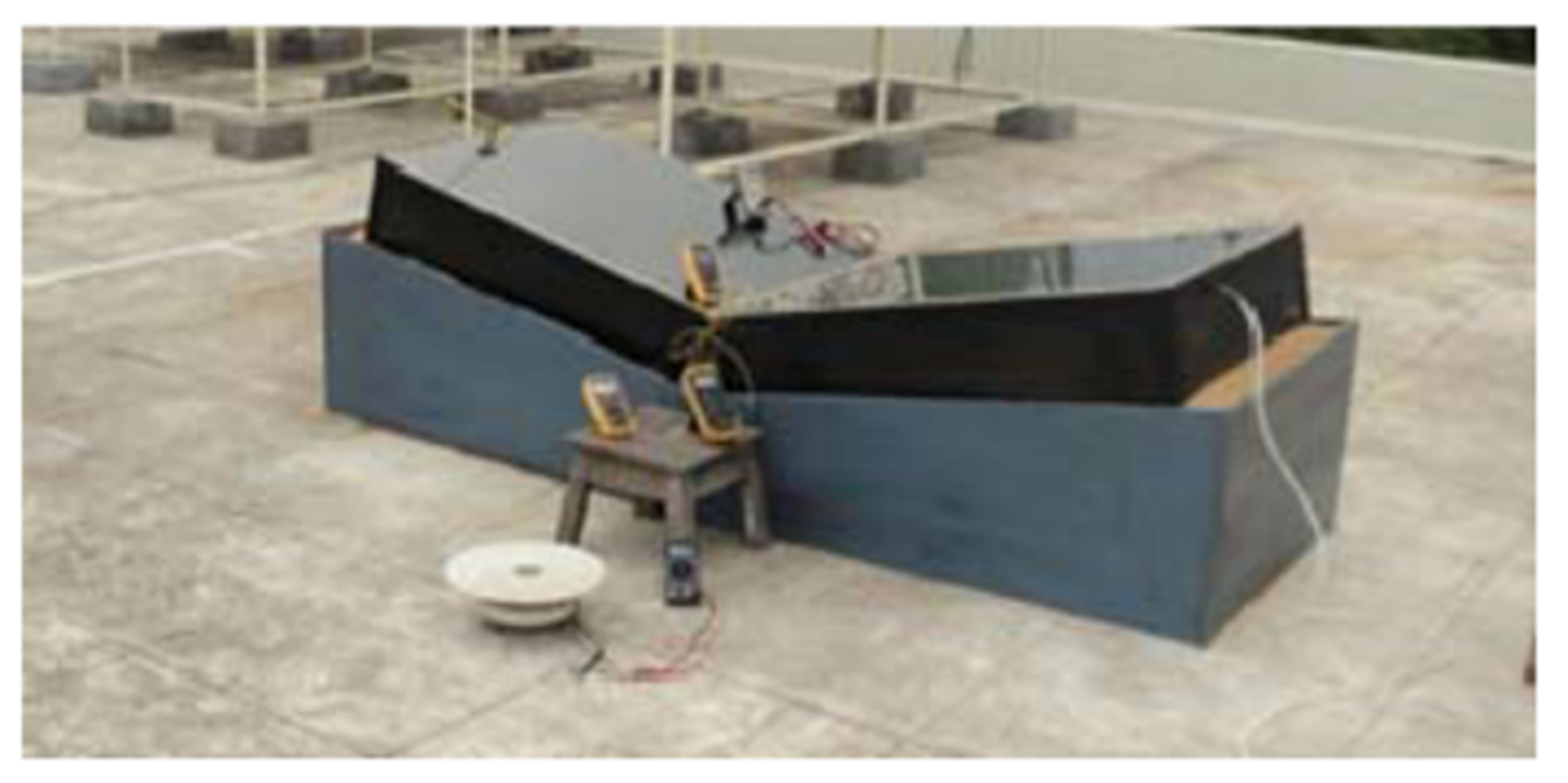
Figure 1. Photographic view of “V” type solar still.

Figure 2. Photographic view of corrugated absorber.
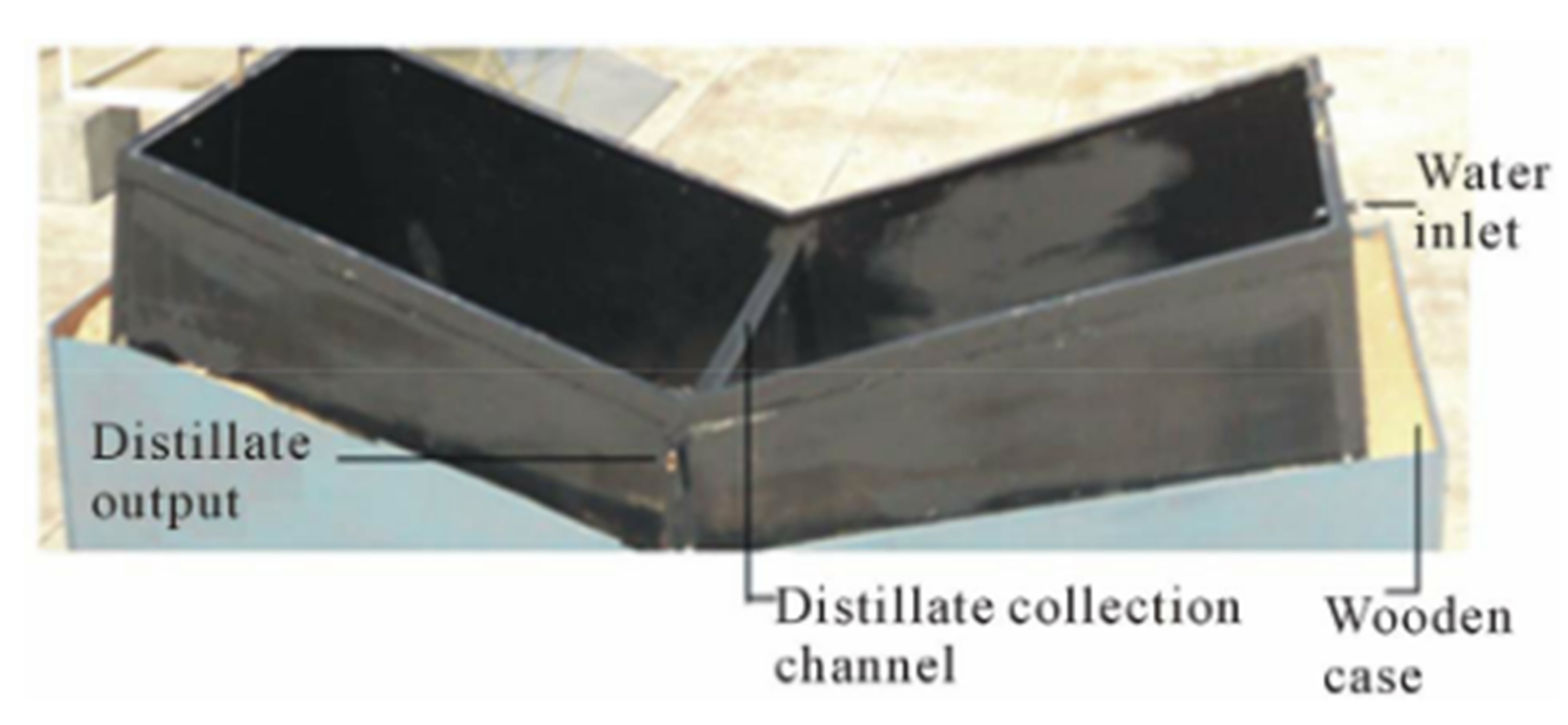
Figure 3. “V” type solar still without glass cover.
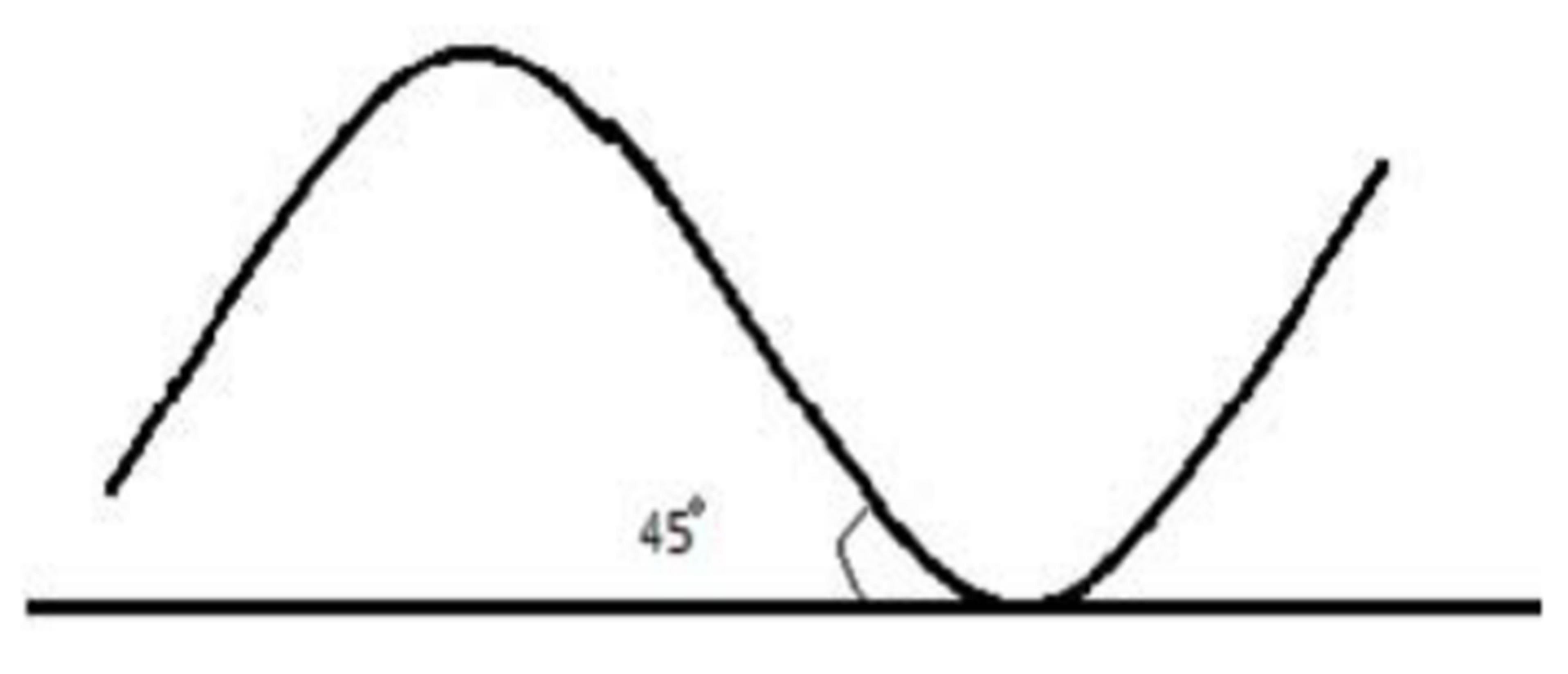
Figure 4. Corrugated wick.
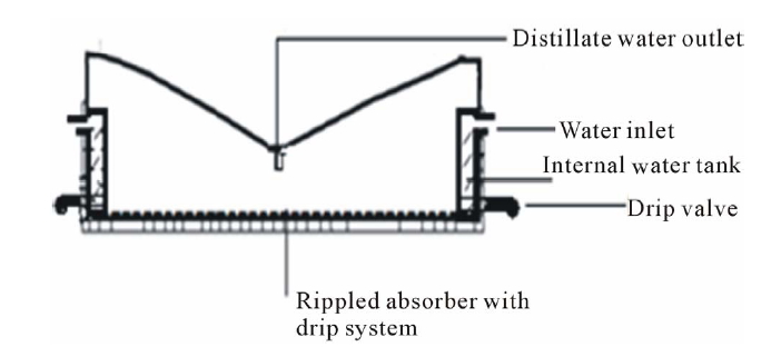
Figure 5. Schematic representation of “V” type solar still.
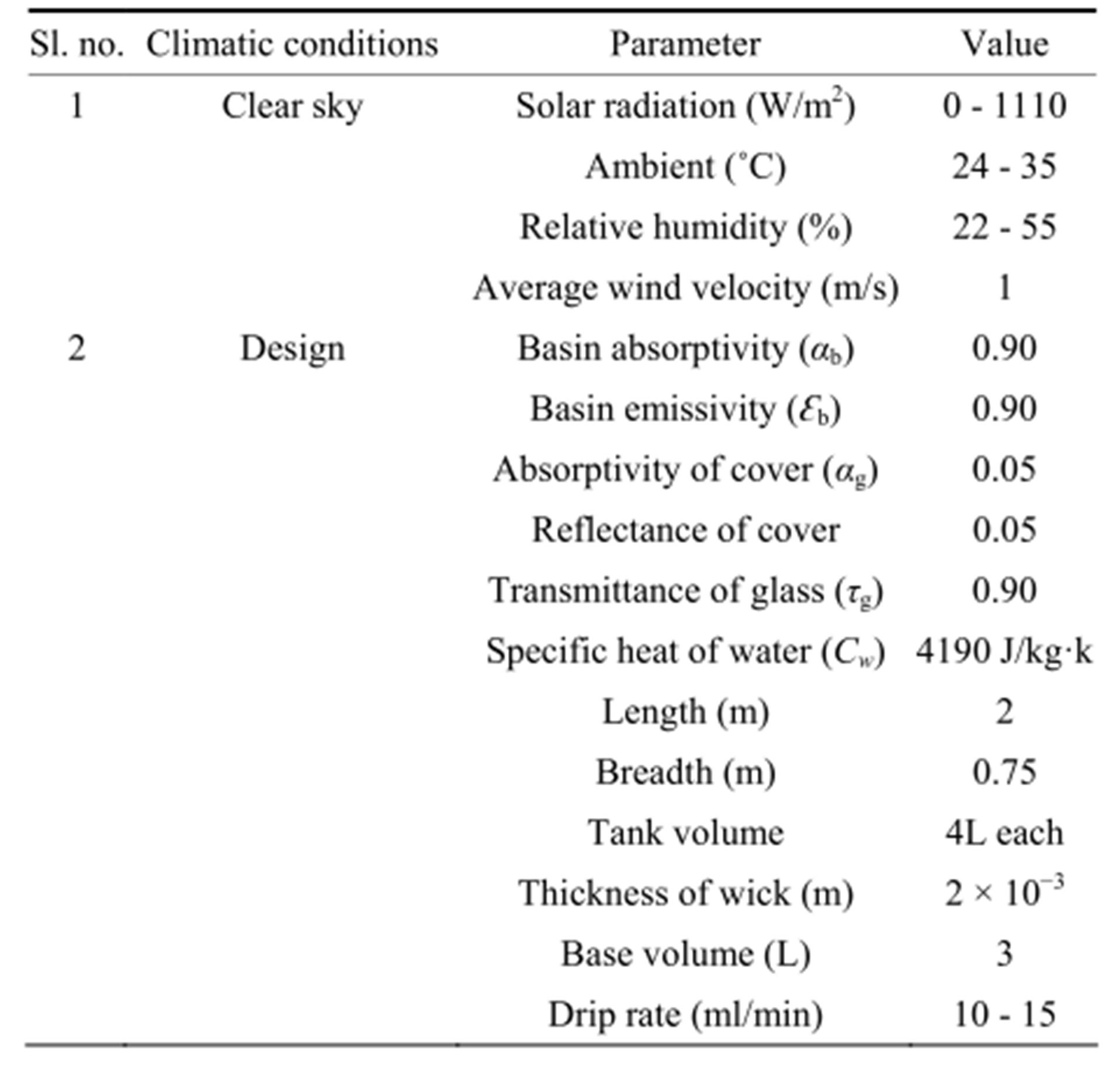
Table 1. Still technical and operation details.
the basin with a wooden case. The inter space between still and wooden case was filled with saw dust to reduce heat loss at low cost. The top cover of the still has been made by glass thickness of 3 mm (Figure 1). An inward slope of the glass cover was maintained towards the center of the still and the cover was cemented by chemical adhesive to minimize air leakage (Figure 2). An outlet is also provided to drain out distilled water and a 2˚ slope is maintained for the water collection channel for smooth outward flow of distilled water (Figure 3). The experiments were carried out in the time duration of 9 h - 18 h. The hourly variation of various temperatures like ambient (Tamb), glass (Tg) and wick (Tw) were recorded using calibrated K-type thermocouples. Commercial grade jute was used as wick because of wide availability and low cost. Accuracies and error percentage of various measuring instruments used in the experiment are shown in Table 2" target="_self"> Table 2.
The solar radiation transmitted through glass cover is largely absorbed by the basin; hence, the temperature increases. Part of the energy absorbed by the basin is transferred by convection to the basin water. Evaporated water releases its latent heat of condensation on the glass cover and condensate trickles down and is collected by the trough. The objective of this work was to study the performance as well as comparison between two solar still configurations: plane wick integrated with drip system and corrugated wick integrated with drip system. The main advantage of the still was two vertically internally molded water tanks on either side; act as hot water reservoir from which wick is made wet by drip valve system. A mathematical modeling is proposed to validate experimental results.

Table 2. Accuracies and error for various measuring instruments.
3. Mathematical Model
The following assumptions are made in the mathematical modeling of the system. Heat loss is negligible across the side wall and basin liner of the system. Variation of incident angle of solar radiation is negligible. The glass plates and basin are assumed to be parallel. The energy balance of the glass cover and wick surface are necessary to model the system.
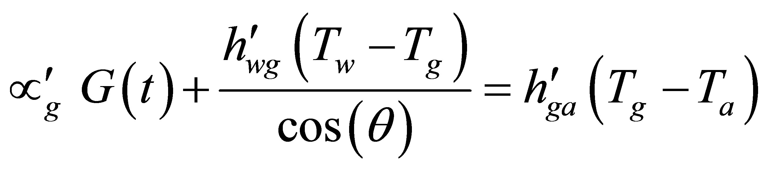
3.1. Energy Balance for Glass Cover
The energy received by the glass cover includes incident solar radiation and energy received from wick surface. The energy balance equation for the glass cover is given byEnergy received by the glass cover = Energy lost from the glass cover
 (1)
(1)
 (2)
(2)
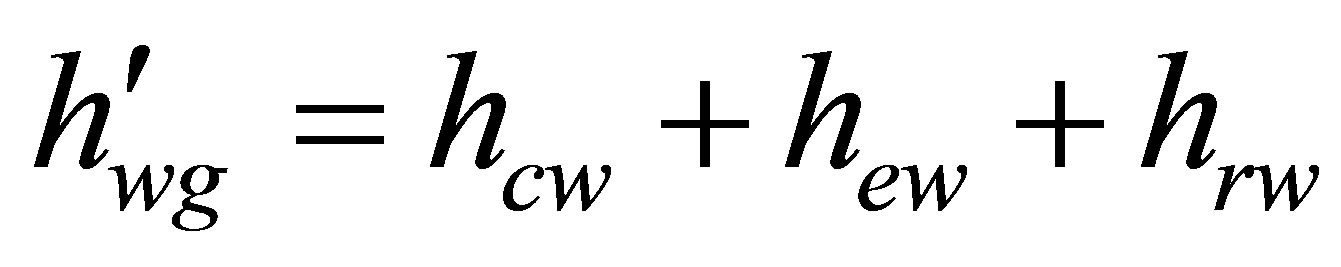
The convective heat transfer coefficient from the wick surface  is given by Dunkle’s relation [9],
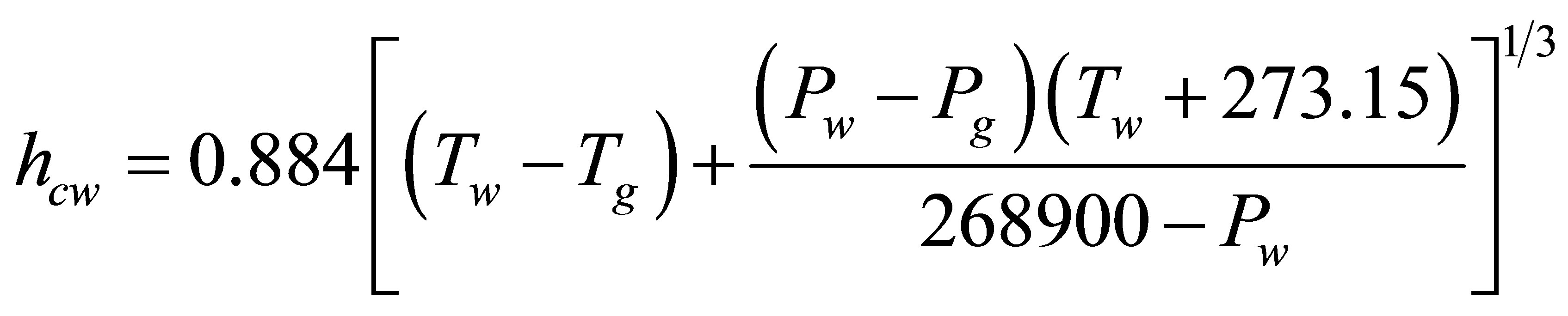 (3)
(3)
The partial pressure of water vapour in the air in N/m2, is estimated for a given temperature (˚C) using the following correlation [10],
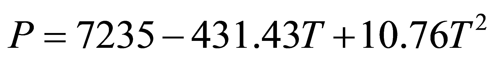 (4)
(4)
The evaporative heat transfer coefficient  is given by,
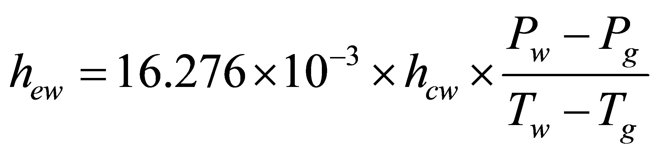 (5)
(5)
The radiation heat transfer coefficient  is given by [11],
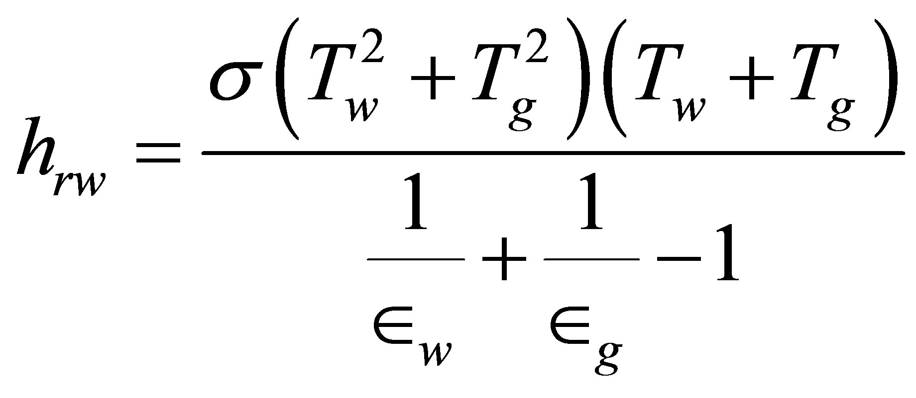 (6)
(6)
Heat transfer from glass to air is due to convection and radiation.
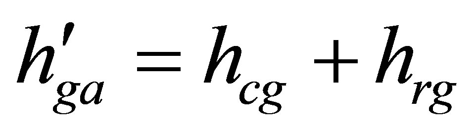 (7)
(7)
The convective heat transfer coefficient from the glass cover is given by [12],
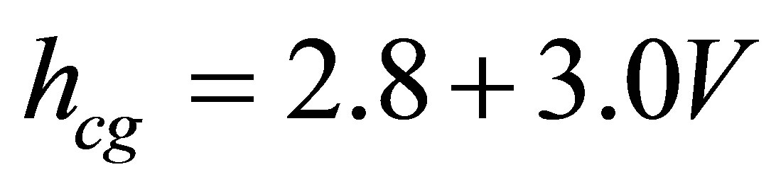 (8)
(8)
The radiative heat transfer from the glass to air is given by,
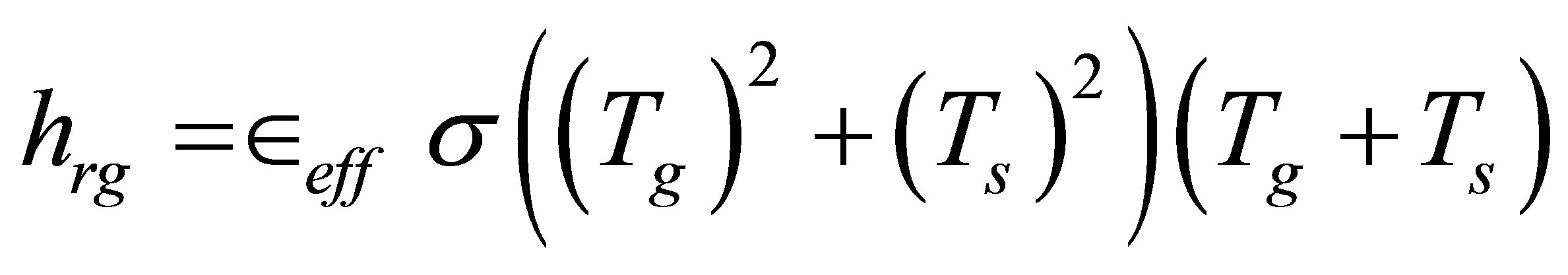 (9)
(9)
The sky temperature  is given by [13],
 (10)
(10)
3.2. Energy Balance for Wick Surface
Solar energy received by the wick surface is used for raising the temperature of wick surface together with water. Energy is lost from the wick to glass cover by convection, evaporation and radiation. Energy balance for the wick surface is given byEnergy received by wick surface = Energy loss from wick surface
 (11)
(11)
Using energy balance equations of wick and glass, modified differential equation in Tw can be written as
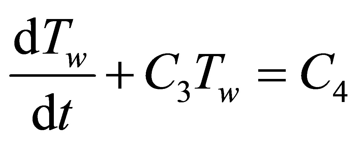 (12)
(12)
where,
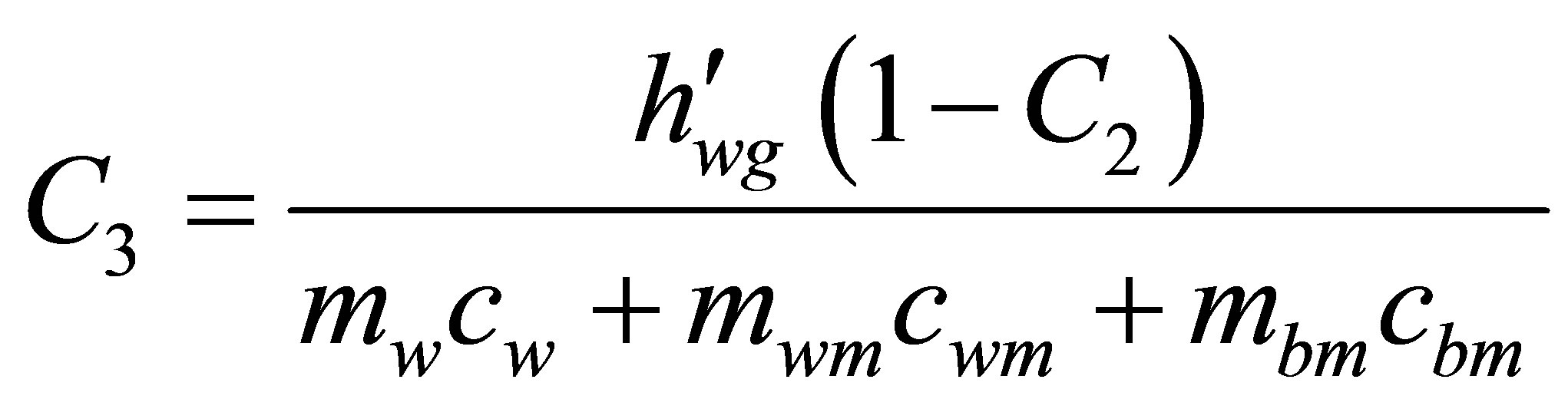 (13)
(13)
 (14)
(14)
 (15)
(15)
 (16)
(16)
4. Result and Discussion
Initial temperature of water, wick and glass were assumed to be equal to ambient temperature and average wind speed was found to be 1 m/s. In theoretical modeling ambient temperature was taken as 30˚C. Experiments were conducted with Plane wick (θ = 0˚) and corrugated wick (θ = 45˚). The hourly variation of solar intensity and ambience temperature corresponding to March 2013 is presented in figure 6, which have been used for computation. Radiation received was in the range of 0 W/m2 to 1000 W/m2. The ambient temperature is in the range of 24˚C - 35˚C. The fresh water productivity of the still is generally proportional to daily solar radiation. The measured ambient temperature is lower than other temperatures.
The temperature profile of corrugated-“V” type solar still is shown in Figure 7" target="_self"> Figure 7. Experimental variation of wick temperature was in the range of 30˚C - 65˚C. The mean standard deviations between theoretical and experimental values are less than 7%. Numerically calculated wick temperature was in the range of 30˚C - 68˚C. No significant variation was found between theoretical and experimental values of glass temperature. The variation was in the range of 30˚C - 52˚C. In both cases, the temperatures increases first and reaches a maximum and then decreases. Variation of experimental and theoretical values of glass and wick temperature for plane-“V” type solar still is shown in Figure 8" target="_self"> Figure 8. Experimental variation of wick temperature was in the range of 30˚C - 68˚C. The mean standard deviations between theoretical and experimental values are less than 6%. Numerically calculated wick temperature was in the range of 30˚C - 65˚C. Variation between theoretical and experimental values of glass temperature was negligible. The variation was in the range of 30˚C - 52˚C (exp) and 30˚C - 55˚C (the). On comparing figures 7 and 8, wick temperature is higher for plane “V” type solar still. The solar radiation received was uniformly distributed over the absorber. The area of plane wick was less than that of corrugated wick. So the solar energy absorbed per unit area is higher and hence temperature is larger. The distillate output is independent of absorber area unless we provide any method of solar concentration. Figure 9 presents the experimental results

Figure 6. Solar radiation.

Figure 7. Variation of temperature (corrugated-“V” type solar still).
Figure 8. Variation of temperature (plane-“V” type solar still).
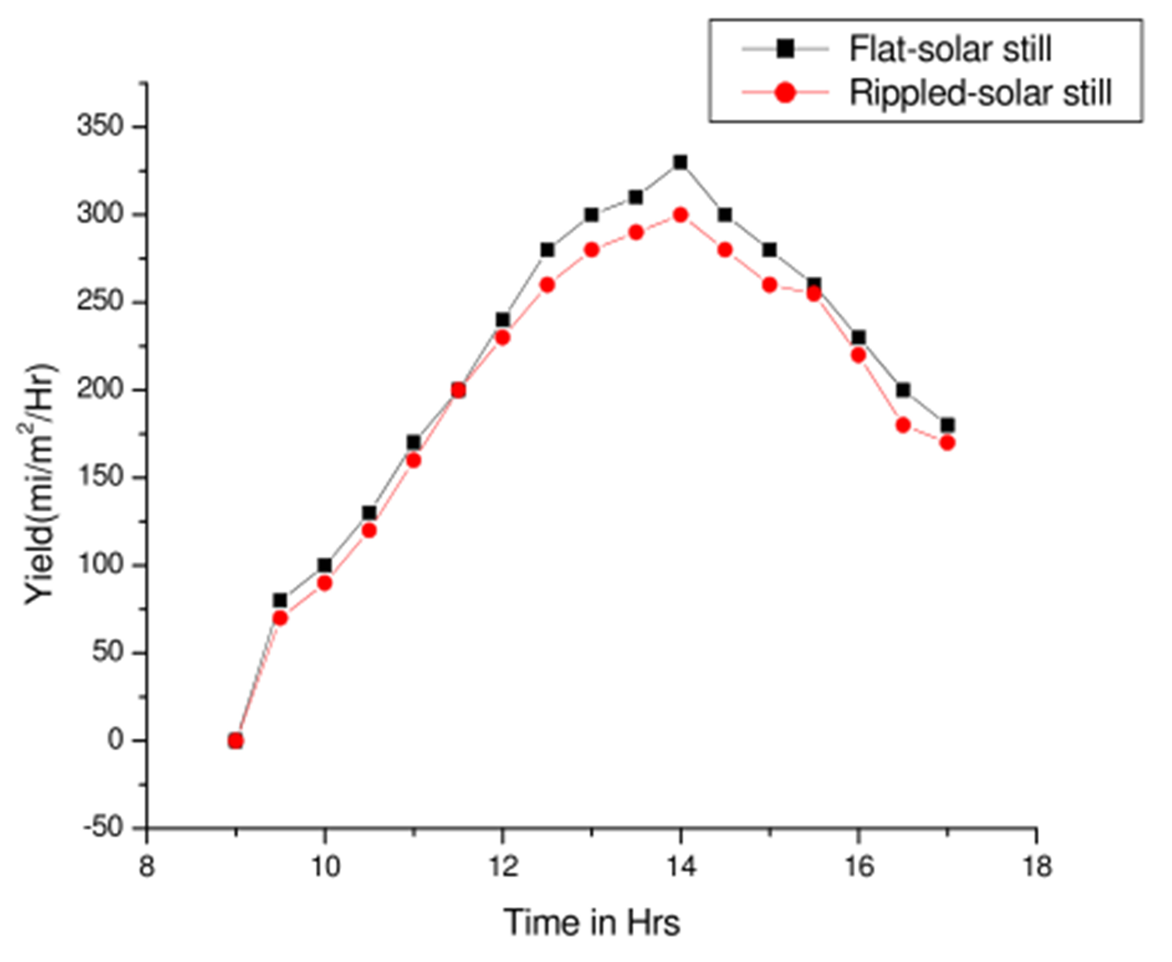
Figure 9. Variation of output.
of the hourly yield for corrugated and plane mode. The total amount of daily productivity obtained by the plane-“V” type solar still was 2800 ml/m2/day. Finally, with corrugated absorber, productivity decreased to 2200 ml/m2/day.
5. Conclusion
In the present study, several conclusions can be obtained as follows: 1) solar radiation received is independent of absorber area, 2) structural modification of wick/m2 has no significance, 3) in wick-type solar stills, plane wick with drip system could be efficient, 4) the wick temperature for the plane wick is higher than that of the corrugated wick and the still output is higher for the plane system, 5) a change in the angle (0˚ - 45˚) causes decrease in distillate yield by 600 ml/m2/day, and finally 6) the proposed mathematical model gave good match with experimental results.
REFERENCES
- J. A. Duffie and W. A. Beckaman, “Solar Engineering of Thermal Processes,” Madison, 1991.
- V. Velmurugan, M. Gopalakrishnan, R. Raghu and K. Srithar, “Single Basin Solar Still with Fin for Enhancing Productivity,” Energy Conversion and Management, Vol. 49, No. 10, 2000, pp. 2602-2608. http://dx.doi.org/10.1016/j.enconman.2008.05.010
- N. A. Minasian and A. A. Al-Karaghouli, “An Improved Solar Still: The Wick Basin Type,” Energy Conversion and Management, Vol. 36, No. 3, 1995, pp. 213-217. http://dx.doi.org/10.1016/0196-8904(94)00053-3
- M. K. Phadatare and S. K. Verma, “Influence of Water Depth an Internal Heat and Mass Transfer in a Plastic Solar Still,” Journal of Desalination, Vol. 217, No. 1-3, 2007, pp. 267-275. http://dx.doi.org/10.1016/j.desal.2007.03.006
- K. Kalidasa Murugavel and K. Srithar, “Performance Study on Basin Type Double Slop Solar Still with Different Wick Materials and Minimum Mass of Water,” Renewable Energy, Vol. 36, No. 2, 2011, pp. 612-620. http://dx.doi.org/10.1016/j.renene.2010.08.009
- H. M. Yeh and L. C. Chen, “The Effect of Climatic, Design and Operational Parameters on the Performance of Wick-Type Solar Distillers,” Energy Conversion and Management, Vol. 26, No. 2, 1986, pp. 175-180.
- S. Talbert, J. Eibling and G. Lof, “Manual on Solae Distillation of Saline Water,” US Department of the Interior, OSW, R&D, Report No. 546, 1970.
- K. Tanaka, A. Yamashita and K. Watanabe, “Solar World Forum,” Vol. 2, Pergamon Press, Oxford, 1982.
- R. V. Dunkle, “Solar Water Distillation, the Roof Type Still and a Multiple Effect Diffusion Still,” International Developments in Heat Transfer, ASME, Proceeding of International Heat Transfer, Part V, University of Colorado, 1961, p. 895.
- T. Siaka and M. Pierre, “A Numerical Model and Experimental Investigation for a Solar Still in Climatic Conditions in Abidjan (COTE DTOIRE),” Renewable Energy, Vol. 11, 1997, pp. 319-330. http://dx.doi.org/10.1016/S0960-1481(96)00131-0
- J. Duffie and W. Beckman, “Solar Engineering of Thermal Processes,” 2nd Edition, John Wiley and Sons, New York, 1991.
- J. H. Watmuff, W. W. S. Charters and D. Proctor, “Solar and Wind Induced External Coefficients Solar Collectors,” Revue Internationale Heliotechnique, Vol. 2, 1977, p. 56.
- V. B. Sharma and S. C. Mullick, “Estimation of HeatTransfer Coefficients, the Upward Heat Flow, and Evaporation in a Solar Still,” ASME Journal of Solar Energy Engineering, Vol. 113, 1991, pp. 36-41. http://dx.doi.org/10.1115/1.2929949
Nomenclature
C: Specific heat (J/kgK)
h’: Heat transfer coefficient (W/m2K)
G: Intensity of solar radiation-diffused (W/m2)
m: Mass flow rate (kg/s)
p: Pressue (N/m2)
T: Temperature (K)
t: Time (s)
V: Velocity of wind (m/s)
α’: Fraction of solar radiation absorbed
θ: Angle of the ripple
ε: Emissivity hwg: Heat transfer coefficient (water-glass) (W/m2·K)
hga: Heat transfer coefficient (glass-ambience) (W/m2K)
σ: Stefan-Boltzman’s constant, W/m2·K4
Subscripts
g: Glass
w: Water
a: Ambient
cw: Convective from water
ew: Evaporative from water
rw: Radiative from water
cg: Convective from glass
rg: Radiative from glass
eff: Effective
S: Sky
wm: Wick material
bm: Base material
NOTES
*Corresponding author.