Smart Grid and Renewable Energy
Vol.4 No.3(2013), Article ID:33026,6 pages DOI:10.4236/sgre.2012.43030
First Measurements with a Linear Mirror Device of Second Generation
![]()
Isomorph srl, Via di Visogliano 9/R1, Trieste, Italy.
Email: Grassmann@isomorph.it
Copyright © 2013 H. Grassmann et al. This is an open access article distributed under the Creative Commons Attribution License, which permits unrestricted use, distribution, and reproduction in any medium, provided the original work is properly cited.
Received April 4th, 2013; revised May 6th, 2013; accepted May 14th, 2013
Keywords: Renewable Energy; Solar Thermal; Concentrated Solar Energy; Solar Torrefaction; Linear Mirror
ABSTRACT
In 2011, an innovative technique for concentrating solar light has been introduced in the market—the Linear Mirror. It is a very simple device, and it works well also in winter and in northern climates. In 2012, it was certified with the Solar Keymark. Based on this technology, a further improved device was developed and was presented here—the Linear Mirror of second generation (or Linear Mirror II). This is a multi-purpose machine, which overcomes some of the limitations of the previous device. First measurements with the Linear Mirror II are presented in this paper.
1. Introduction
Solar energy can be used for many different applications, and not only for heating buildings. It can be used, for example, to provide process heat to many industries, for solar cooling, and also to provide steam for steam engines or turbines [1]. Therefore, from a purely technical point of view, solar energy could substitute the use of oil, coal, gas and nuclear power to a large extent. All of these applications do exist and are being used.
In addition, there are other applications which are in principle known, and in this sense do exist already, but are not applied as industrial tools. An example is the use of solar heat energy for the torrefaction or pyrolysis of cheap organic matter, like wood, grass, grass silage, maize silage or similar substances for producing biocarbon. This bio-carbon material could be used even in conventional power plants and it would offer a way of storing solar energy for long periods of time. Solar torrefied bio-carbon could be produced in summer (when the plants grow) and it could be used in winter for operating conventional power plants with a CO2-neutral process. It is theoretically known beyond doubt that this technology could be applied, but it is not applied in practice.
However, despite these technologies are known since many years, we are still making very little use of solar energy.
One important reason for this situation is the price of solar collectors. There are cheap flat plat collectors, but they cannot reach high temperatures at a good efficiency, in particular not in norther climates and in winter. Systems, which provide temperatures of 100˚C and more also in winter and in northern climates do exist, but are rather complex and expensive.
One example is given by the heliostat systems [2]. They consist of a certain number of mirrors, each one driven by two motors, which reflect the Sun light onto a common target. One may ask, whether for a heliostat system of N mirrors, 2 N motors are indeed needed, or whether a smaller number of motors could also be used without compromising the performance of the system. To the best of our knowledge, literature does not show a solution to this “N mirror problem”.
2. The Linear Mirror
2.1. The Linear Mirror I: The First Generation
Isomorph srl is a physics research company which developed what originally has been referred to as Linear Mirror. It consists of an array of 6 × 4 mirrors, which follows the Zenith position of the Sun by means of one motor. The mirrors are all connected to each other by bars and by levers of different lengths, and each mirror is mounted on an axis of its own, with a particular inclination, so that all mirrors together follow the Sun Azimuth, driven by a second motor. All mirrors are therefore operated by a total of two motors, and they send the Sun light to an absorber mounted in front of the mirror matrix (see Figure 1). The system is described in more details in [3].
One reason for calling this device Linear Mirror is because the movement of each mirror during the day is obtained from the linear movement of one motor (“clock movement”) by means of levers of different lengths and by means of rotations, which are representing the execution of mathematical linear function in a physical device.
The Linear Mirror has been certified with the Solar Keymark [4] and it has been tested accordingly by an independent test laboratory [5]. Its key features are: a reflecting surface of 7.4 m2 (aperture), a thermal power of 4.5 kW, a relatively small energy loss to the environment of 500 W for a temperature difference ΔT = 70˚C, and therefore a good efficiency also in winter and in northern climates. The Linear Mirror can bring its mirror matrix into a park position which, to some extent, protects the mirrors against snow and hail. The Linear mirror can also go to the park position when energy is not needed, for instance when the boiler is hot.
Since the Linear Mirror has a very simple and sturdy construction, and since it uses only two electrical motors, its cost is reasonable: one Linear Mirror unit can substitute up to 600 liters of oil per year, so that—together with government incentives—the time return of investment can be as short as five years. This original Linear Mirror had also a number of limitations. First of all, its price was competitive only in comparison with the oil price. The price for gas may be lower than that for oil, in which case a rather longer time for the return of investment may result. To further reduce the production cost one would like to simplify the mechanical structure.
Secondly, since the absorber was mounted on a pair of levers in front of the mirror matrix, and was moved to-
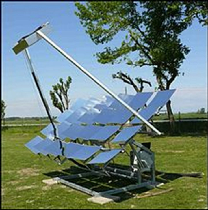
Figure 1. The Linear Mirror of first generation.
gether with the mirror matrix by the same motor, the absorber could not be too heavy. A light weight absorber was used from the company Energie Solaire [6], not being able to support pressures above 3 bar, therefore limiting the possible temperature range with water as a heat carrier. At its position the absorber was very much exposed to the wind, which again would have made operation at higher temperatures problematic.
For these reasons, Isomorph srl developed a second generation device, which avoids those limitations, and which is called Linear Mirror II [7]. It has the additional advantage to be constructed in a very modular way so that any number of additional mirrors can be added: in this way, in the future also high-temperature applications will be possible, for instance for driving steam motors or turbines in order to produce electricity.
Since the introduction of the Linear Mirror II early in 2013, the previous device got referred to as Linear Mirror I.
2.2. The Linear Mirror II
The Linear Mirror II is a direct application of the physics law of reflection. This law states that, given an incident ray of light, this one, the normal to the mirror and the reflected light ray lay in the same plane, and that the angle between the incident ray and the mirror normal is equal to the angle between the reflected ray and the mirror normal. Said differently, the mirror normal divides in two halves the angle between the incident and the reflected ray. One can then identify a mathematical figure and construct a corresponding mechanical device, with those properties: there must be three vectors in a common plane, and one of these vectors must always divide the angle between the other ones, where the dividing vector must be normal to the mirror surface. Such a figure is well known in Euclidean geometry, and is called kite, or also deltoid. In a kite, one of the diagonals divides the angle between two of the sides of the kite. For instance in Figure 2 the diagonal x divides the angle between the sides a and b. In the most simple case, as in Figure 2, all sides of the kite quadrilateral may be of equal length.
This geometrical figure can also be executed as a hardware device, defined by joints between the different
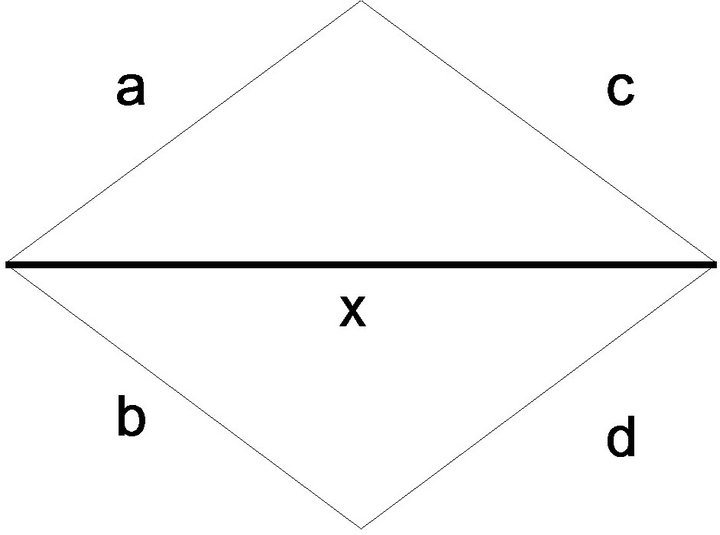
Figure 2. A kite.
sides of the deltoid, for instance (a,b) may denote the joint between sides a and b: the diagonal x would become the mirror normal, a metal bar, on which the mirror is mounted. The mirror is supported by the joint (x,a). Since a and d and b and c are parallel, it is not necessary to actually build all of the sides of the deltoid.
For instance, one may choose the side a to represent the direction of the reflected light—that is, it needs to point towards the absorber. Side c would be a metal bar, rotating around joint (a,c), and being connected with x by means of a sliding joint. If side c is brought (by means of motors) in a direction parallel to the incident sun rays, then the mirror normal (and therefore the mirror) correspondingly will be in a position, where it reflects the sun rays to the absorber.
If we now combine any number of mirrors into a multimirror concentrating device, each mirror will have a direction a, which is particular to this individual mirror, but is not moving in time (if the absorber does not move). The direction c instead changes during the day, but is always the same for all the different mirrors, since the Sun is at a very large distance compared to the setup size. Therefore, all bars a can be connected and be moved together. For instance, by one motor for the movement is in the Zenith direction, and one motor for the movement is in Azimuth. The position and the number of the mirrors are not constrained.
A device with eight mirrors is shown in Figure 3.
Each of its eight mirrors consists of four segments with a slight relative inclination of 2˚, resulting in a light concentration, which varies through the day, but is typically a factor of two.
The total reflecting surface is 13.8 m2 (aperture). The absorber is the same as the one used for the Linear Mirror I, with dimensions of 86 cm × 62 cm. It is placed in front of the mirror matrix at a distance of five meters, as shown in Figure 4.
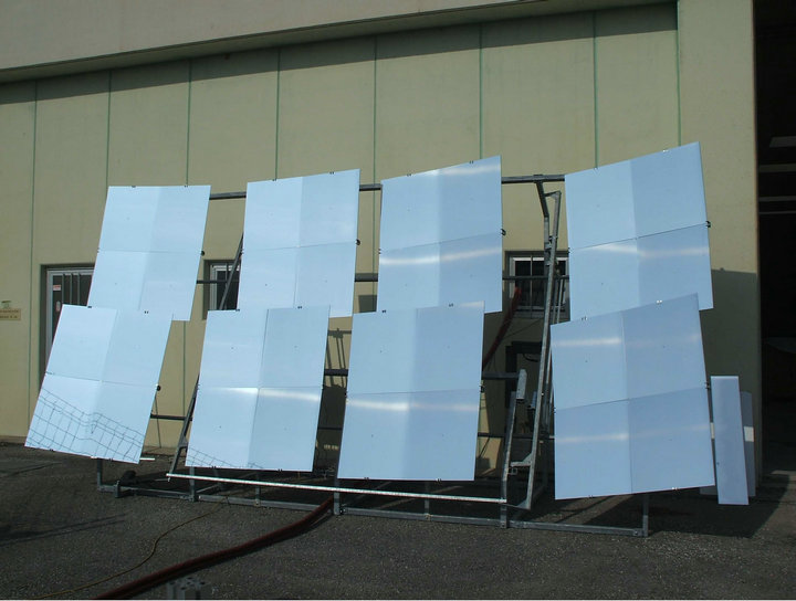
Figure 3. A Linear Mirror II device with eight mirrors.
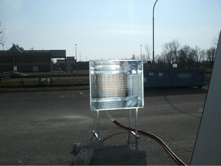
Figure 4. The absorber.
The reflecting surfaces around the absorber have two functions: first they capture the stray light, which does not hit the absorber directly, increasing the light concentration somewhat. Secondly, these mirrors protect the absorber against wind–air is a good isolator, as long as it is stagnant. The tracking of the Sun is done by means of a micro-controller, based on local time and geographic position of the Linear Mirror II system. The control electronics, together with the motor operation consume an average of about 2 W of electrical power. All in all, the resulting system is very simple, both for what concerns its construction and its way of operation.
3. Expected Performance
The main difference between Linear Mirror I and II is the way of how the mirrors are mounted mechanically. The mirror material, the control electronics, the absorber and the hydraulic circuit are all the same. Therefore it should be possible to extrapolate the expected performance of the Linear Mirror II from the well known values documented for Linear Mirror I.
The Linear Mirror I has total reflecting surface of 7.4 m2 (aperture area) and a thermal power of 4.5 kW (peak) at a temperature difference to the environment of 50˚C. The Linear Mirror II has a larger reflecting surface of 13.8 m2. Correspondingly it should have a thermal power of 4.5 × 13.8/7.4 kW = 8.4 kW in first approximation.
4. Measurement Results
For these measurements the orientation of the Linear Mirror II device deviated from the South direction by 15˚ toward East. The absorber was placed in front of the mirror plane on the ground at a distance of five meters. As a heat carrier water was used, in a closed circle, at a pressure of three bar. The circulation pump was a Wilo Eco. In order to simplify the evaluation of the measurement, the flow was kept constant at 400 liters per hour. Instead of a conventional boiler, a non-insulated open barrel with 200 liters of water was used, so that also when arriving at a temperature of 100˚C in the closed circuit, heat energy could be dissipated by means of boiling. Figure 5 shows the heat power developed during a sunny day and the temperature at the outflow of the absorber.
The temperature at the inflow of the absorber and at the outflow were measured with two PT100 sensors with a measurement precision of 0.3˚C. The power developed by the absorber was determined from the difference between these two temperatures, the known mass flow and the specific heat of water. The water temperature reaches values above 100˚C around noon. The thermal power reaches 8.0 kW, this is in reasonable agreement with the estimate given in the previous chapter (of 8.4 kW).
5. Other Applications
The absorber of the Linear Mirror II is in a fixed position: this fact opens new applications with respect to the Linear Mirror I. For instance it becomes possible to heat stationary technical devices for solar torrefaction or pyrolysis. These techniques can be used to create high quality fuels, burning with little pollution and at high temperatures.
5.1. Torrefaction
It would go beyond the scope of this article to investigate the process of torrefaction itself, we rather want to perform a feasibility study, exploring whether there are unforeseen technical limitations, which might hinder solar torrefaction by means of a linear Mirror II system.
For this feasibility study we prepared a steel container with dimensions 30 cm × 30 cm × 10 cm. It was filled with hay. The torrefaction fumes were guided to the outside through a corrugated steel tube. The steel container was placed in the focal area of the Linear Mirror II, as shown in Figure 6.

Figure 5. Heat power during a sunny day, and temperature at the outflow of the abosrber.

Figure 6. Steel container for torrefaction.
The steel container was equipped with a temperature sensor, mounted inside.
Figure 7 shows the temperature measured in the steel container, during its exposition to the concentrated Sun light of the Linear Mirror II.
In Figure 7, we see how the torrefaction steel container reaches a temperature in excess of 250˚C within ten minutes.
During the heating process, dense white smoke exited from the steel tube. We have ignited this fume and the gases by means of a cigarette lightner. The resulting flame is shown in Figure 8.
One can see the dense white fume exiting from the pipe, and one can see how it is consumed by the flame. The flame itself does not produce fume in a visible way. Since the solar torrefaction is based on an external heat source, not on an internal combustion, the fumes are formed from the hay in the absence of oxygen, therefore they are not oxidized and burn.
The final result of the torrefaction is shown in Figure 9.
We did not have the tools to perform a chemical analysis, but the appearance is that of bio-carbon, while the texture of the hay can still be seen. Further study will be carried on.
5.2. Use of Thermal Oil
For an industrial application, it would be of advantage to use an existing industrial torrefaction machine. For instance, those used for torrefying coffee beans. It might be difficult to expose the torrefaction volume of such a machine to the direct Sun light from the Linear Mirror II. Using thermal oils to transfer heat might be instead a better solution.
We have therefore also performed a feasibility study on the use of thermal oil in the Linear Mirror II. We used the” Shell heat transfer oil S2” [8], which can support
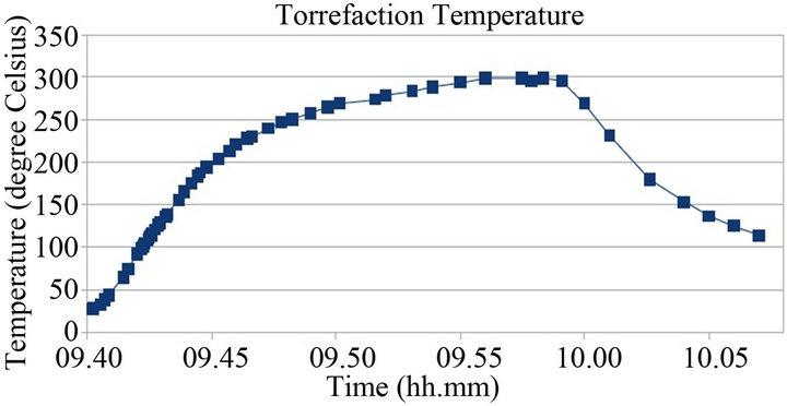
Figure 7. Temperature measured in the steel container, during its exposition to the concentrated sun light.
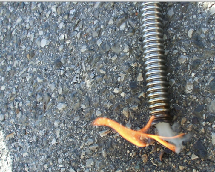
Figure 8. Flame at the exit of the torrefaction steel tube.
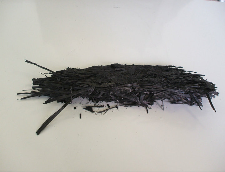
Figure 9. Material resulting from the torrefaction of hay.
temperatures up to 320˚C. However, pumps operating at this high temperature are very expensive. We therefore limited our study to using a Calpeda pump, which is certified up to 180˚C. With this pump, oil was circulated through the same kind of absorber from Energie Solaire as used in the first measurement. The use of oil instead of water did not cause any problem. The flow was about 30 liters/min at a 20˚C oil temperature, and reached 50 liters/min above 120˚C. We heated the oil flow to 180˚C, since this was the maximum temperature allowed for the pump, without encountering problems.
According to the producer of the absorber, the absorber can without problems stand a temperature of 300˚C.
6. Outlook
The Linear Mirror II—which is already on the market as an industrial product with all needed certifications—can readily be used as it is for many applications, for solar cooling, industrial process heat, of course also for heating. The device presented in this paper consists of eight single mirrors, and a resulting light concentration factor of about 20. This is already enough to achieve the temperatures needed for torrefaction of about 250˚C.
Given its construction principle, additional mirrors can be added, so that a higher light concentration results. In this case it should not be a problem to reach temperatures significantly higher than 300˚C, which would allow the operation of steam motors or even turbines.
However we note, that even a very cheap concentrating device developing very high temperatures always will be limited in its use by the fact that in large parts of the world there is virtually no Sun in winter time. Even a solar device, which produces heat or electrical power for free is of no use in winter time, when operated in northern climates.
Therefore the use of concentrated solar energy would be very much more useful for the torrefaction or the pyrolysis of cheap plant material, like grass or silage or similar. The process is very similar to the roasting of coffee, it does not cause any fundamental technical difficulties. The bio-carbon, which would be the product of the solar torrefaction process could at least substitute large amounts of natural coal without any fundamental changes in infrastructure. The use of bio-carbon from solar torrefaction would also be a way of storing solar energy for the winter without losses.
Often the transition of our society to a solar society—a transition which will have to occur at some point—is seen as a process of suffering: it is assumed that we will have to do the most severe efforts to save energy, that we will have to use battery driven cars, which can operate only over small distances, that we will have to pay always higher prices for energy and that a lot of investments are needed to transport electrical energy over very large distances, with all the problems this will necessarily have.
We propose that by using the Linear Mirror for driving solar torrefaction this suffering can be avoided. Existing coal power plants can still be used with bio-carbon. Biocarbon can also be used to produce liquid fuels for cars. Energy would remain cheap, mainly due to the sturdiness of the linear mirror II. After a few years of operation the initial investment would be payed back, but due to the construction of the linear mirror from steal and aluminum, a very long live is expected for such a system, resulting in free energy for many years to come. Not even the cheapest gas rates can beat free solar energy.
REFERENCES
- J. A. Duffie and W. A. Beckman, “Solar Engineering of Thermal Processes,” NASA STI/Recon Technical Report A, Vol. 81, 1980.
- B. Rohr, “The Promise of Small Heliostats,” Northeast Sun, Spring, 2009, pp. 7-12.
- H. Grassmann, M. Salvagni and A. Prest, “The Linear Mirror,” Isomorph Letters B, Vol. 1, 2008. http://letters.isomorph.it
- Solar Keymark, 2013. http://en.wikipedia.org/wiki/Solar_keymark
- Report of Measurement According to EN12975-1,2: 2006+A1:2010 http://www.isomorph.it/solutions/renewable-energies/solar-thermal/Linear%20Mirror/test-report-fraunhofer-institute
- Energie Solaire SA. http://www.energie-solaire.com
- Isomorph Holding AG, “The Solar Wall,” Isomorph Letters B, Vol. 3, 2011. http://letters.isomorph.it
- http://s04.static-shell.com/content/dam/shell/static/ind/downloads/lubes-b2b/other-shell-lubricants/heat-transfer-oil.pdf