Smart Grid and Renewable Energy
Vol.2 No.1(2011), Article ID:4032,11 pages DOI:10.4236/sgre.2011.21001
Fault Diagnosis in Distribution Networks with Distributed Generation
![]()
Department of Electrical & Control Engineering, Collage of Engineering & Technology, Arab Academy for Science & Technology, Miami, Egypt.
Email: amanyelz@yahoo.com
Received November 7th, 2010; revised November 22nd, 2010; accepted November 28th, 2010.
Keywords: Cooperative Systems, Relay Agent, Fault Diagnosis, Distributed Generation, Wavelet Transform, Entropy Calculation
ABSTRACT
The penetration of distributed generation (DG) in distribution power system would affect the traditional fault current level and characteristics. Consequently, the traditional protection arrangements developed in distribution utilities are difficult in coordination. Also, the reclosing scheme would be affected. With the rapid developments in distribution system automation and communication technology, the protection coordination and reclosing scheme based on information exchange for distribution power system can be realized flexibly. This paper proposes a multi-agent based scheme for fault diagnosis in power distribution networks with distributed generators. The relay agents are located such that the distribution network is divided into several sections. The relay agents measure the bus currents at which they are located such that it can detect and classify the fault, and determine the fault location. The proposed technique uses the entropy of wavelet coefficients of the measured bus currents. The performance of the proposed protection scheme is tested through simulation of two systems. The first system is a benchmark medium voltage (MV) distribution system and the second system is practical 66 kV system of the city of Alexandria.
1. Introduction
The traditional power systems, which are based on large fossil fuel fired power generation plants, long distance transmission lines and hierarchical control centers, are changing. A large number of distributed generation units including renewable energy sources such as wind turbines, PV generators, fuel cells together with Combined Heat and Power (CHP) plants, are being integrated into power systems at distribution level. The penetration of DGs changes the traditional distribution power system short circuit power, fault current level and the characteristics of the fault current, such as amplitude, direction and distribution [1].
Most distribution network protection schemes are initially designed without DGs. The nature of distribution network can be radial or meshed. Traditionally, radial networks are protected using coordinated overcurrent relays whereas meshed networks are protected using directional overcurrent relays [2].
To deal with the problem of protection of distributed networks with the penetration of DGs, distribution utilities impose interconnected regulations. These regulations are often based on IEEE Std. 1547, 2003 [4] and recommend the tripping of DGs even for remote faults in order to maintain the protection coordination during fault. According to [4], immediate tripping of DGs is recommended also if a power island is created. That is why protection schemes, which are capable of immediate identifying and isolating faults after their occurrence, are required. These schemes can ease the requirement for the disconnection of DGs to ensure protection coordination and enable intentional power islands.
Several protection schemes have been proposed in literature [1-8] in order to address the shortcomings in current DG interconnection practices and protection problems associated with DGs.
This paper proposes a multi-agent based protection scheme to classify and locate the fault in a distribution network with DG. The proposed technique aims to locate and isolate a faulty section in a distribution system with DGs. It is based on entropy calculation of wavelet coefficients of the three phase current signals. This method uses only current signals measured by relay agents at the boundaries of the network sections to identify the type of fault if it is a three line to ground (3LG), single line to ground (LG), double line to ground (DLG) or a line to line (LL) fault. It also determines the phases included in fault and the bus or line at which the fault occurred. The performance of the proposed algorithm is investigated through the simulation of a benchmark MV distribution system and part of the 66 kV network if Alexandria. The results proved the effectiveness of the proposed protection scheme under different conditions of fault type, fault location and fault resistance.
2. Analysis of Three Phase Power System Transients
2.1. Modal Transformation
In three-phase systems, many different fault types depending on the phase involved or the involvement of ground can occur. In order to diagnose such types of faults, currents and/or voltages of all three-phase quantities must be analyzed. However, the amount of processing can be reduced by transforming three-phase quantities into modal components.
The modal transformation resolves three-phase signals in a coupled network into three uncoupled modal components, namely, 1) the ground mode; 2) aerial mode-1; and 3) aerial mode-2 components. For nontransposed multiphase systems, an eigenvector-based frequency-dependent transformation matrix is required to convert the quantities from phase domain to modal domain. For balanced and ideally transposed lines, a frequency-independent, real transformation matrix, such as Clarke transformation, can be used. Although practical distribution systems do not satisfy the aforementioned conditions, a frequency-independent real transformation matrix can be used to obtain somewhat decoupled signals that can be advantageous in transient-based fault location.
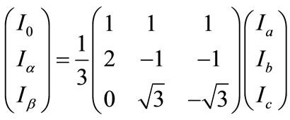
The relationship between the Clarke components and the phase components is given by
 (1)
(1)
where, Ia, Ib and Ic are the phase currents and I0, Ia and Iβ are the respective Clarke components. Transients in the phase currents are well reflected in the Clarke components.
2.2. Wavelet Transformation and Entropy Calculation
Lots of fault information is included in the transient components. So it can be used to identify the fault or abnormity of equipments or power system. It can also be used to deal with the fault and analyze its reason. This way the reliability of the power system will be considerably improved.
Transient signals have some characteristics such as high frequency and instant break. Wavelet transform is capable of revealing aspects of data that other signal analysis techniques miss and it satisfies the analysis need of electric transient signals. Usually, wavelet transform of transient signal is expressed by multi-revolution decomposition fast algorithm which utilizes the orthogonal wavelet bases to decompose the signal to components under different scales. It is equal to recursively filtering the signal with a high-pass and low-pass filter pair. The approximations are the high-scale, low-frequency components of the signal produced by filtering the signal by a low-pass filter. The details are the low-scale, high-frequency components of the signal produced by filtering the signal by a high-pass filter. The band width of these two filters is equal. After each level of decomposition, the sampling frequency is reduced by half. Then recursively decompose the low-pass filter outputs (approximations) to produce the components of the next stage [9,10].
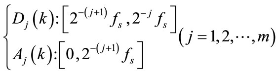
Given a discrete signal x(n), being fast transformed at instant k and scale j, it has a high-frequency component coefficient Dj(k) and a low-frequency component coefficient Aj(k). The frequency band of the information contained in signal components Dj(k) and Aj(k), obtained by reconstruction are as follows [11].
 (2)
(2)
where, fs is the sampling frequency.
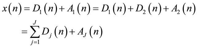
The original signal sequence x(n) can be represented by the sum of all components as follows [11].
 (3)
(3)
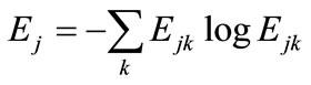
Various wavelet entropy measures were defined in [9]. In this paper, the nonnormalized Shannon entropy will be used. The definition of nonnormalized Shannon entropy is as follows [11].
 (4)
(4)
Where Ejk is the wavelet energy spectrum at scale j and instant k and it is defined as follows.
 (5)
(5)
3. Proposed Agent-Based Fault Diagnosis
3.1. Protection Arrangement Based on Relay Agents
Protective relays detect fault occurrence in a power system and isolate that part of the power system to prevent fault from affecting the whole power system. Traditional protective schemes generally used dual systems of primary and backup protection relays for high sensitive and reliable protection of the system. The primary protection relays are usually current differential relaying that has a high accuracy of fault detection. The backup protection relays are usually distance relaying that work with local power system information only [12].
With the introduction of distributed generation and deregulation, the power system impedance and fault currents through protective devices would change. The protective devices are therefore difficult to be coordinated [13].
The distribution power system automation techniques have been widely adopted and the infrastructure of communication has been developed. The protection schemes based on microprocessors with communication capabilities are utilized, so that the status of the relays and breakers can be obtained from the distribution power system supervisory control and data acquisition system, which can serve as an information exchange platform. Based on the platform, the protection coordination and adaptation can be dealt with flexibly [1].
The concept of a cooperative protection system with an agent model (relay agent) was first proposed by Y. Tomita, et al. back in 1998 [12]. The application of this concept has been proposed in [14] and [13] to build an intelligent, adaptive protection system.
The relay agents allow the cooperation between numbers of equipments. The cooperation of relay agents enables the flexible utilization of all hardware resources by any equipment, so that various adaptive protective functions are realized.
The fundamental concepts of relay agents as proposed by Y. Tomita, et al. [12] are as follows:
1) Equipment Agent This type of agent manages data and functions proper to each pieces of equipment. Network topology data of a power system are expressed as link data between equipment agents. This enables distribution of power system information.
2) Mobile Agent This type of agent moves between equipment agents or protection system equipment to utilize data and functions distributed in equipment agents.
3) Protector Agent This type of agent dispatches mobile agents to detect a fault or isolate a fault-detected zone. These agents act as supervisors for detection and isolation.
4) Reorganizer Agent This type of agent reorganizes the agent space according to changes in power system conditions. The cooperative protection system with relay agents must have an agent processing facility, which allows the agent to transfer to the different hardware through communication networks or to communicate with other agent in the different hardware.
In this paper, the distribution network is divided into a number of network segments as shown in Figure 1 for fault isolation purpose. Each network segment can be isolated from the rest of the system for a fault inside it by opening the circuit breakers (CBs) at its interconnection
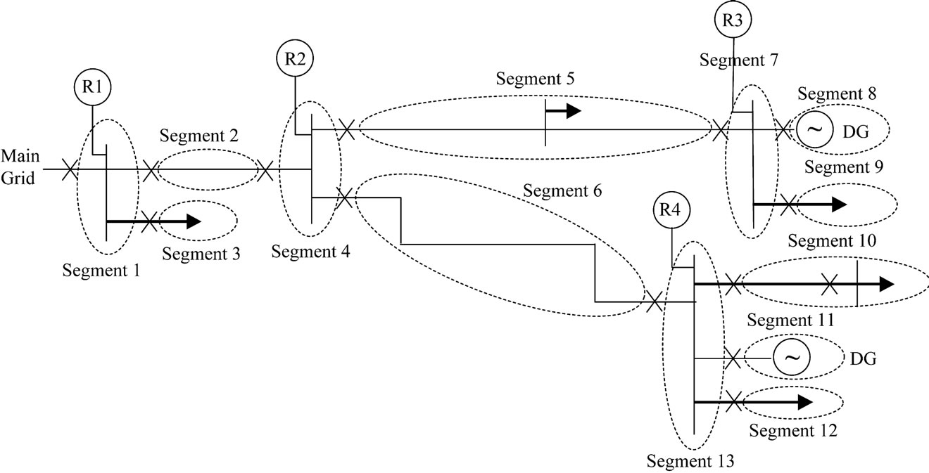
Figure 1. Structure of proposed protection scheme.
points to the system. The three phase bus currents are measured and fed to the relay agents which are placed at the interconnection points of different network segments. The relay agents exchange data between each other through a telecommunication network. A simple algorithm based on the information collected by different relay agents is proposed to classify and then locate the fault such that the faulted area can be correctly isolated.
3.2. Fault Classification Using Current Transients
An analysis of all possible types of fault in three phase system, i.e. LG faults (AG, BG, CG), LL faults (AB, BC, CA), DLG faults (ABG, BCG, CAG) and 3LG faults (ABCG), is carried out. In this paper, the proposed algorithm determines the type of fault first, then the phases included in fault and finally it determines the fault location.
The sum of absolute entropies of wavelet coefficients of the Clarke component I0 is used to determine the type of fault if it is 3LG, LG, DLG, or LL fault. Next, the sum of absolute entropies of wavelet coefficients of the three phase currents (Ia, Ib, and Ic) are used to determine the phases included in fault. Finally, the values of the sum of absolute entropies of wavelet coefficients of Clarke components Ia and Iβ are used to locate the fault. The mother wavelet used was ‘Symlets’ in addition to Shannon entropy.
4. Simulation and Results
4.1. Test System 1
The distribution system shown in Figure 2 was simulated using the SIMULINK power system blockset. This system has been derived from the CIGRE MV benchmark test distribution system [15]. The system used in the study has two DGs. DG-1 is a 1500-kVA three-phase induction generator running from a wind turbine and DG-2 is a 200-kVA small-size three-phase synchronous generator running from a hydro turbine. The generators were simulated using detailed machine models. Distribution lines–lengths of which range from 0.24 km to 4.89 km–were modeled using transmission line p sections. The loads, which include highly unbalanced three-phase loads as well as single-phase loads, were modeled using series RLC loads. Each relay agent takes the measurements from the corresponding busbar located near the relay agent. Locations of the relay agents were determined based on the network configuration, interconnection to the grid, and locations of the DGs. It was assumed that the relay samples current signals at a frequency of 10 kHz.
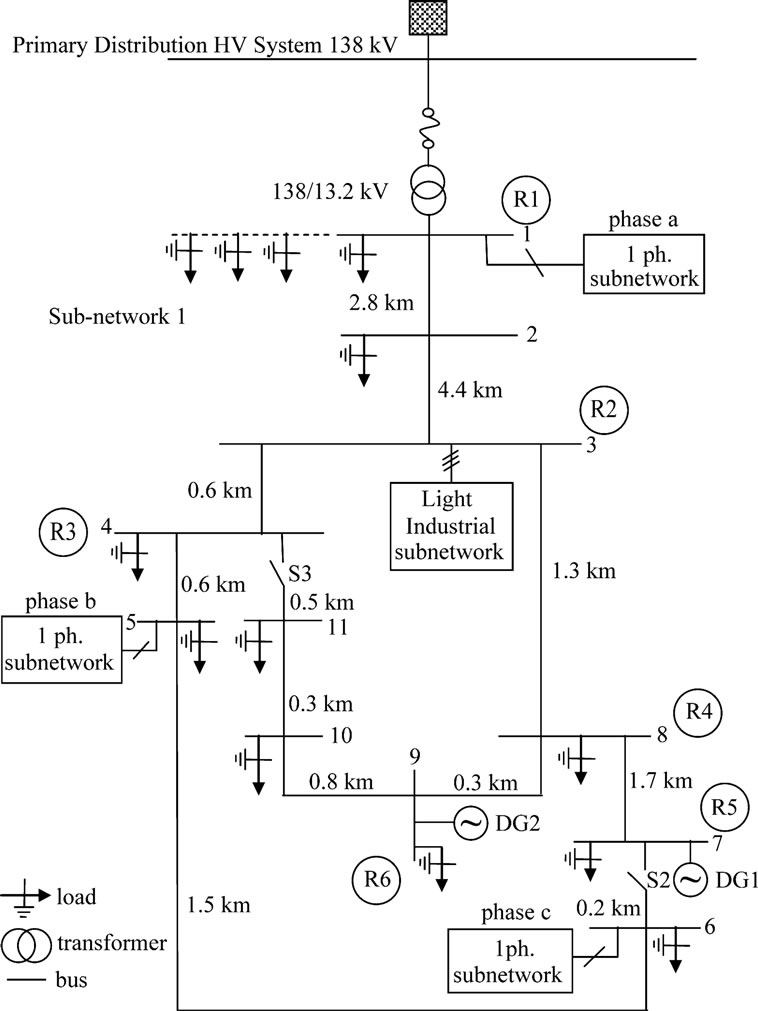
Figure 2. MV test distribution system.
4.1.1. Radial Network
In the proposed CIGRE MV benchmark network, switches S2 and S3 were kept open to simulate a radial network.
For a fault at bus 3, the sum of absolute entropy of wavelet coefficients of I0 monitored at relay agent R1for different fault types are listed in Table 1. The fault was simulated from 10/60 to 15/60 s with fault resistance Rf = 10 W.
From the values of sumI0 shown in Table 1, the fault type if it was a 3LG or a LL fault is well defined. In case of LG or DLG faults, sumI0 has nearly the same range of values. In that case sumIa and sumIβ are used to discriminate between a LG fault and a DLG fault. The values of sumIa and sumIβ for currents monitored at relay agent R1 are given in Table 2.
As shown in Table 2, the maximum value of sumIa and sumIβ in case of LG fault is less than 30,000 and in case of DLG fault it is more than 50,000. This way these two types of fault are discriminated from each other.
The next step in the proposed algorithm after determining the fault type is to determine the phases included in fault. To do so the sum of entropies of wavelet coefficients of the three phase currents are used. For the same fault at bus 3, Table 3 lists the values of sumIa, sumIb
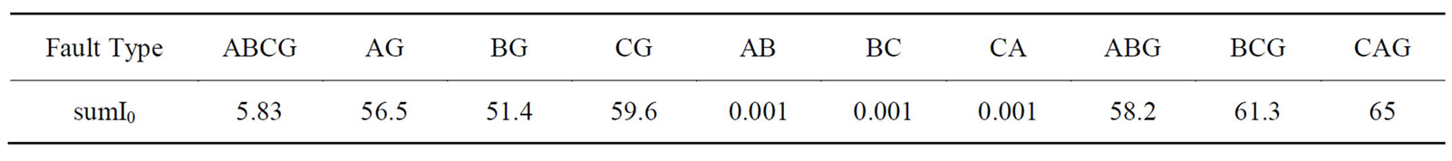
Table 1. The sum of absolute entropy of wavelet coefficients of I0 monitored at R1 for a fault at bus 3.
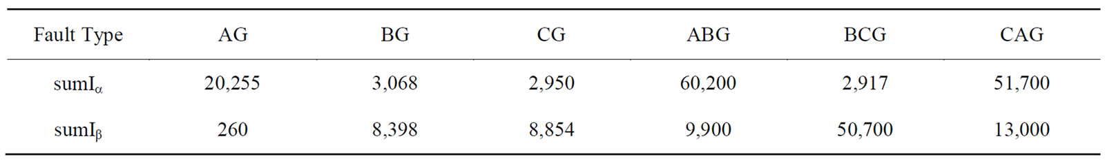
Table 2. The values of sumIa and sumIβ of currents monitored at R1 for a fault at bus 3.
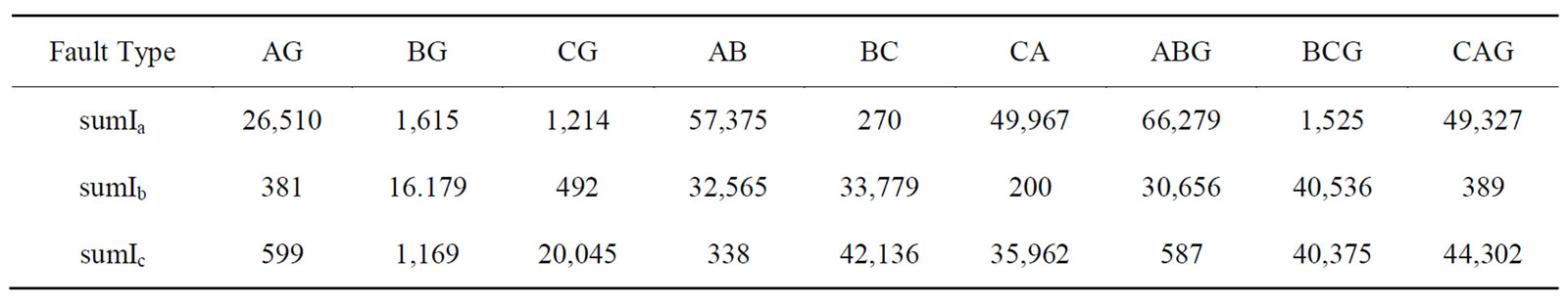
Table 3. The values of sumIa, sumIb and sumIc of currents monitored at R1 for a fault at bus 3.
and sumIc for currents monitored at relay agent R1 in case of LG, LL and DLG faults.
As shown from the results in Table 3, in case of LG fault, the faulted phase is that having the maximum sumI. For example, for an AG fault, sumIa is greater than sumIb and sumIc. In case of LL fault, the phase of minimum sumI is not included. For example, for an BC fault, sumIa is less than both sumIb and sumIc. Finally, in case of DLG fault, also the phase with minimum sum is not included in fault. For example, for an CAG fault, sumIb is less than sumIa and sumIc.
The final step of the algorithm is to determine the fault location. To determine the fault location in case of 3LG and DLG faults the values of sumI0 of currents monitored at different relay agents are used. For example, in case of 3LG at buses 4, 5 or 6, the value of sumI0 for currents monitored at relay agent R3 is used to determine the faulted bus. Where, in that case sumI0 > 10 and if the fault at any other bus sumI0 < 10. To determine the exact fault location the value of sumI0 is used. For fault at bus 4, sumI0 = 55.6. For fault at bus 5, sumI0 = 35.7. For fault at bus 6, sumI0 = 10.4. Table 4 lists the values of sumI0 at R3 for 3LG fault at all buses.
For a DLG fault at buses 9, 10 or 11, sumI0 for currents monitored at relay agent R6 is greater than 500. In the same time, for the same type of fault at any other bus, sumI0 at R6 is less than 1. To determine the exact location of the fault, both the values of sumI0 at relay agent R6 and sumI0 at relay agent R5 are used. Table 5 lists the values of sumI0 at R5 and at R6 for DLG fault at buses 9, 10 and 11.

Table 4. The values of sumI0 of currents monitored at R3 for an 3LG fault at different buses.
In case of LL fault, to determine the faulted bus, the values of sumIa and sumIβ for currents monitored at different relay agents are used. For example, for an AB fault, the fault location is determined by monitoring sumIa at relay agents R1, R3 and R4. Table 6 lists the values of sumIa at R1, R3 and R4 for an AB fault at different buses.
In case of LG fault, sumIa and sumI0, monitored at different relay agents, are used to determine the fault location. For example, for an AG fault, the values of sumI0 at R1, R3, R4 and at R6 are listed in Table 7.
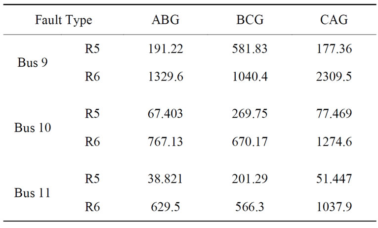
Table 5. The values of sumI0 of currents monitored at R5 and R6 for DLG faults at buses 9, 10 and 11.

Table 6. The values of sumIa of currents monitored at R1, R3 and R4 for an AB fault at different buses.
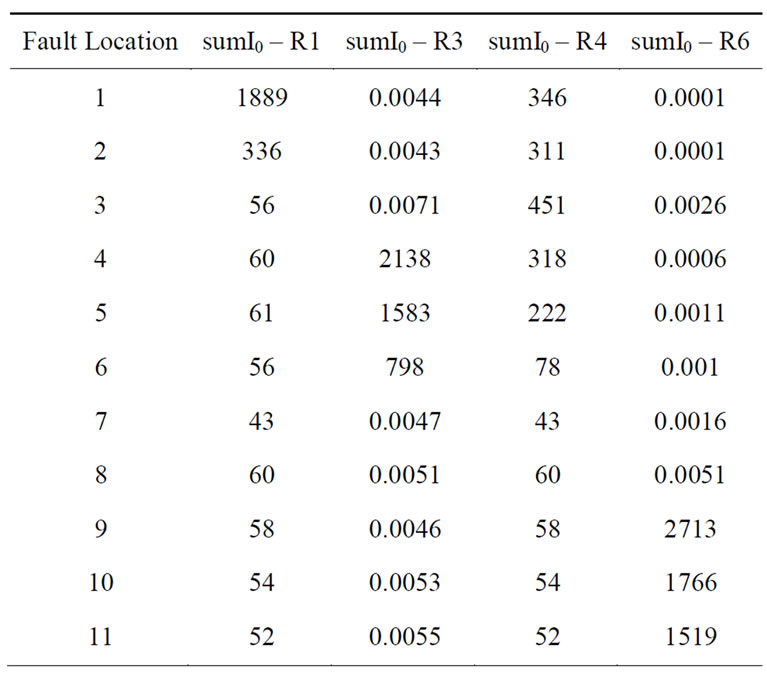
Table 7. The values of sumI0 of currents monitored at R1, R3, R4 and R6 for an AG fault at different buses.
As shown in Table 7, for an AG faults at buses 1 and 2, sumI0 at R1 > 300. For faults at buses 4, 5 and 6, sumI0 at R3 > 700. For faults at buses 9, 10 and 11, sumI0 at R6 > 1000. For faults at buses 3, 7 and 8, the previous values doesn’t apply but sumI0 at R4 for a fault at bus 3 is > 400. In the same way, LG faults including the two other phases could be located.
Also, for faults at different branches connecting two buses, the entropy sum of wavelet coefficients of three phase currents and their Clarke components can identify the type of fault, phases included in fault and fault location. For example, for a 3LG fault at line 3-8, the values of sumIa and sumI0 monitored at relay agent R1 comes between their values for the same fault at bus 3 and at bus 8. Although sumIa and sumI0 monitored at R1 for 3LG fault at bus 4 or 5 comes also between those values at bus 3 and at bus 8, the value of sumI0 at R3 > 10, which is not the case for fault at bus 3, bus 8 or line 3-8. Table 8 lists the values of sumIa and sumI0 as monitored at R1 and sumI0 as monitored at R3 for 3LG fault at buses 3, 4, 5, 8 and line 3-8.
For all cases of fault at different locations, the proposed protection algorithm correctly recognized the type of fault and the faulty segments even with high fault resistance (Rf = 250 W).
4.1.2. Meshed Network
In order to test the proposed protection algorithm in meshed networks, the switches S2 and S3 in the MV network shown in Figure 2 were closed. The same faults simulated in case of the radial system were applied to the meshed network too.
In the same way as in case of radial network, the entropy sum of wavelet coefficients of three phase currents are used to select the phases included in fault. On the other hand, the entropy sum of wavelet coefficients of Clarke components are used to determine the type of fault and its location. Using the entropy calculation through the proposed algorithm made the algorithm very sufficient and correctly succeeded in classifying and locating the fault during all conditions of simulation. That
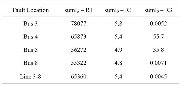
Table 8. The values of sumIa and sumI0 of currents monitored at R1 and R3 for 3LG faults at different buses
is considered as an improvement over the algorithm proposed in [3], which failed to locate the fault in several cases. Tables 9-11 list some results monitored in case of meshed network.
For a fault at bus 3, the sum of absolute entropy of wavelet coefficients of I0 monitored at relay agent R1for different fault types are listed in Table 9. The fault was simulated from 10/60 to 15/60 s with fault resistance Rf = 10 W.
From the values of sumI0 shown in Table 9, the fault type if it was a 3LG or a LL fault is well defined. In case of LG or DLG faults, sumI0 has nearly the same range of values. In that case sumIa and sumIβ are used to discriminate between a LG fault and a DLG fault. The values of sumIa and sumIβ for currents monitored at relay agent R1 are given in Table 10.
As shown in Table 10, the maximum value of sumIa and sumIβ in case of LG fault is less than 1200 and in case of DLG fault it is more than 1600. This way these two types of fault are discriminated from each other.
The next step in the proposed algorithm after determining the fault type is to determine the phases included in fault. To do so the sum of entropies of wavelet coefficients of the three phase currents are used. For the same fault at bus 3, Table 11 lists the values of sumIa, sumIb and sumIc for currents monitored at relay agent R1 in case of LG, LL and DLG faults.
As shown from the results in Table 11, in case of LG fault, the faulted phase is that having the maximum sumI. For example, for an AG fault, sumIa is greater than sumIb and sumIc. In case of LL fault, the phase of minimum sumI is not included. For example, for an BC fault, sumIa is less than both sumIb and sumIc. Finally, in case of DLG fault, also the phase with minimum sum is not included in fault. For example, for an CAG fault, sumIb is less than sumIa and sumIc.
4.2. Test System 2
The test system shown in Figure 3 was simulated using the SIMULINK power system blockset. This system is a part of the 66 kV network of the city of Alexandria, Egypt.
The system used in the study has four DGs each of them are 1 MVA three-phase synchronous generator driven by diesel engines. The system line and load data are give in the Appendix. Each relay agent takes the measurements from the corresponding busbar located near the relay agent. Locations of the relay agents were determined based on the network configuration and locations of the DGs. It was assumed that the relay samples current signals at a frequency of 20 kHz.
In the proposed 66 kV network the following results were taken. For a fault at bus 5, the sum of absolute entropy of wavelet coefficients of I0 monitored at relay agent R3 for different fault types are listed in Table 12. The fault was simulated from 10/50 to 15/50 s with fault resistance Rf = 10 W.
From the values of sumI0 shown in Table 12, the fault type if it was a 3LG or a LL fault is well defined. In case of LG or DLG faults, sumI0 has nearly the same range of values. In that case sumIa and sumIβ are used to discriminate between a LG fault and a DLG fault. The values of sumIa and sumIβ for currents monitored at relay agent R3 are given in Table 13.
As shown in Table 13, the maximum value of sumIa and sumIβ in case of LG fault is less than 70,000 and in case of DLG fault it is more than 70,000. This way these two types of fault are discriminated from each other.

Table 9. The sum of absolute entropy of wavelet coefficients of I0 monitored at R1 for a fault at bus 3 in meshed network.
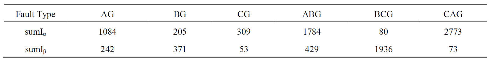
Table 10. The values of sumIa and sumIβ of currents monitored at R1 for a fault at bus 3 in meshed network.
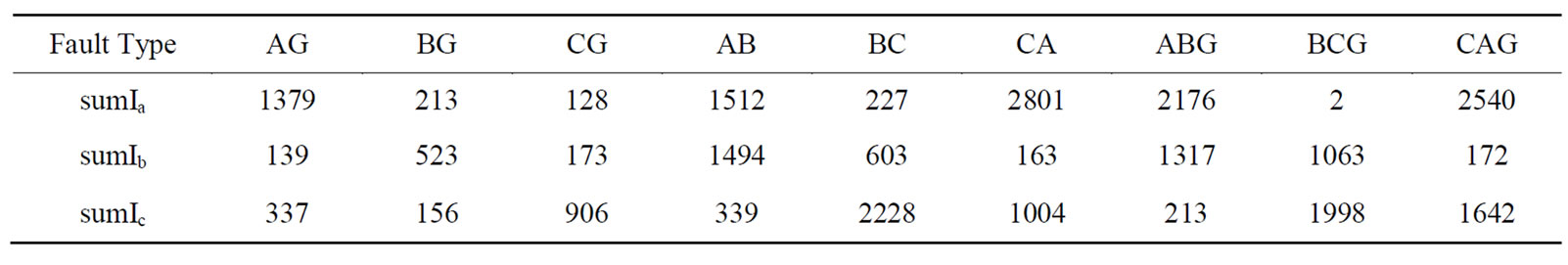
Table 11. The values of sumIa, sumIb and sumIc of currents monitored at R1 for a fault at bus 3 in meshed network.
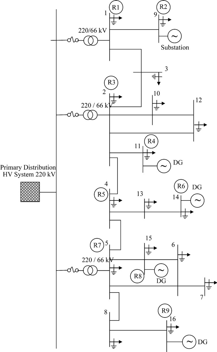
Figure 3. Alexandria 66 kV network.
The next step in the proposed algorithm after determining the fault type is to determine the phases included in fault. To do so the sum of entropies of wavelet coefficients of the three phase currents are used. For the same fault at bus 5, Table 14 lists the values of sumIa, sumIb and sumIc for currents monitored at relay agent R3 in case of LG, LL and DLG faults.
As shown from the results in Table 14, in case of LG fault, the faulted phase is that having the maximum sumI. For example, for an AG fault, sumIa is greater than sumIb and sumIc. In case of LL fault, the phase of minimum sumI is not included. For example, for an BC fault, sumIa is less than both sumIb and sumIc. Finally, in case of DLG fault, also the phase with minimum sum is not included in fault. For example, for an CAG fault, sumIb is less than sumIa and sumIc.
The final step of the algorithm is to determine the fault location. To determine the fault location in case of 3LG and DLG faults the values of sumI0 of currents monitored at different relay agents are used. For example, in case of 3LG, the value of sumI0 for currents monitored at relay agent R5 is used to determine the faulted bus. Table 15 lists the values of sumI0 at R5 for 3LG fault at all buses. As shown in Table 15, the values of sumI0 at all buses are distinguished from each other except at buses 4, 5, 6 and 8. For the fault at these buses the value of sumI0 at R7 are used to determine the fault location.
For a DLG fault at any bus, sumI0 for currents monitored at relay agent R5 is used. Table 16 lists the values of sumI0 at R5 at different buses.
In case of LL fault, to determine the faulted bus, thevalues of sumIa and sumIβ for currents monitored at dif
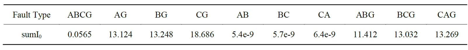
Table 12. The sum of absolute entropy of wavelet coefficients of I0 monitored at R3 for a fault at bus 5.
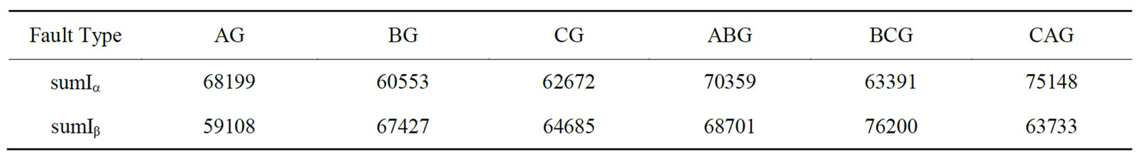
Table 13. The values of sumIa and sumIβ of currents monitored at R2 for a fault at bus5.

Table 14. The values of sumIa, sumIb and sumIc of currents monitored at R3 for a fault at bus 5.

Table 15. The values of sumI0 of currents monitored at R5 and R7 for an 3LG fault at different buses.
ferent relay agents are used. For example, for an AB fault, the fault location is determined by monitoring sumIa at relay agents R2, R3 and R7. Table 17 lists the values of sumIa at R2, R3 and R7 for an AB fault at different buses. For near similar readings at any one of the relay agents the other two agent readings are used to locate the faulted bus.
In case of LG fault, sumIa and sumI0, monitored at different relay agents, are used to determine the fault location. For example, for an AG fault, the values of sumI0 at R3, R4 and at R5 are listed in Table 18.
As shown in Table 18, if the values of sumI0 at relay agent R3 is similar for AG fault at more than one bus as in the case of buses 3, 7 and 13, the values of sumI0 at relay agent R4 is used to identify the faulted bus.
5. Conclusions
The distribution power system automation techniques have been widely adopted and the infrastructure of communication has been developed. The protection schemes based on microprocessors with communication capabilities are utilized, so that the status of the relays and breakers can be obtained from the distribution power system supervisory control and data acquisition system, which can serve as an information exchange platform. Based on the platform, the protection coordination and adaptation
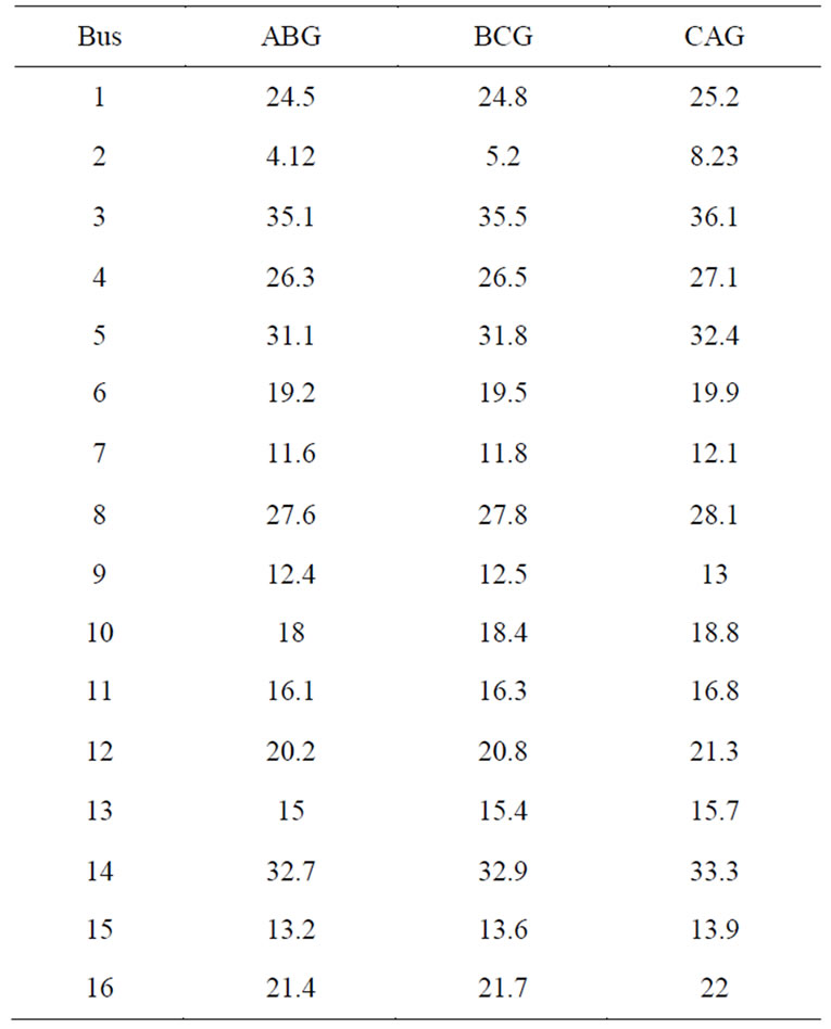
Table 16. The values of sumI0 of currents monitored at R5 DLG faults at different buses.

Table 17. The values of sumIa of currents monitored at R2, R3 and R7 for an AB fault at different buses.
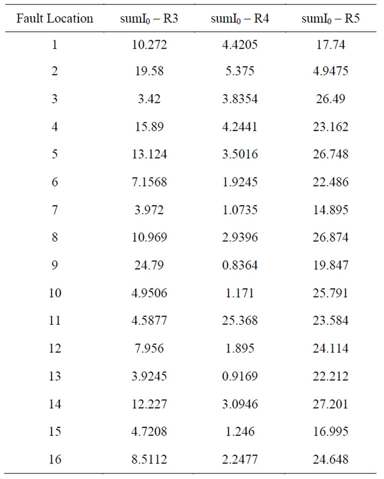
Table 18. The values of sumI0 of currents monitored at R3, R4 and R5 for an AG fault at different buses.
can be dealt with flexibly. In this paper, a new agentbased fault diagnosis scheme was proposed. The algorithm used the entropy calculation along with wavelet transform of current signals to classify and locate the fault in distribution network with distributed generation. The relay agents exchange data between each other through a telecommunication network. The proposed algorithm, based on the information collected by different relay agents, was able to classify and then locate the fault such that the faulted area can be correctly isolated. Simulation carried out using the CIGRE MV benchmark system and the practical 66 kV system of Alexandria showed that the proposed protection scheme is capable of classifying and locating the fault under different fault conditions, for radial and meshed networks.
REFERENCES
- Z. Chen and W. Kong, “Protection Coordination Based on Multi-Agent for Distribution Power System with Distribution Generation Units, 2007, pp. 1-5. http://vbn.aan.dk/fbpretrieve/14217079
- P. Barker and R. W. de Mello, “Determining the Impact of Distributed Generation on Power Systems: Part 1—Radial Power Systems,” Proceedings of IEEE Power Engineering Society Summer Meeting, Seattle, July 2000, pp. 1645-1658.
- N. Perera, A. D. Rajapakse and T. E. Buchholzer, “Isolation of Faults in Distribution Networks with Distributed Generators,” IEEE Transactions on Power Delivery, Vol. 23, No. 4, October 2008, pp. 2347-2355. doi:10.1109/ TPWRD.2008.2002867
- “IEEE Standard for Interconnecting Distributed Resources with Electric Power Systems,” IEEE Std., 2003.
- A. K. Pradhan, A. Routray and S. M. Gudipalli, “Fault Direction Estimation in Radial Distribution System Using Phase Change in Sequence Current,” IEEE Transactions on Power Delivery, Vol. 22, No. 4, 2007, pp. 2065-2071. doi:10.1109/TPWRD.2007.905340
- W. El-Khattam and S. Sidhu, “Restoration of Directional Overcurrent Relay Coordination in Distributed Generation Systems Utilizing Fault Current Limiter,” IEEE Transactions On Power Delivery, Vol. 23, No. 2, 2008, pp. 576-585. doi:10.1109/TPWRD.2008.915778
- H. H. Zeineldin and J. L. Kirtley, “A Simple Technique for Islanding Detection with Negligible Nondetection Zone,” IEEE Transactions on Power Delivery, Vol. 24, No. 2, April 2009, pp.779-786. doi:10.1109/TPWRD. 2009.2013382
- S. M. Brahma and A. A. Girgis, “Development of Adaptive Protection Scheme for Distribution Systems with High Penetration of Distributed Generation,” IEEE Transactions on Power Delivery, Vol. 19, No. 1, 2004, pp. 56-63. doi:10.1109/TPWRD.2003.820204
- Z. Y. He, X. Q. Chen and G. M. Luo, “Wavelet Entropy Measure Definition and Its Application for Transmission Line Fault Detection and Identification (Part I: Definition and Methodology),” Proceedings of International Conference on Power System Technology, Chongqing, 2006, pp. 1-6.
- Z. Y. He, X. Q. Chen and G. M. Luo, “Wavelet Entropy Measure Definition and Its Application for Transmission Line Fault Detection and Identification (Part III: Transmission Line Faults Transients Identification),” Proceedings of International Conference on Power System Technology, Chongqing, 2006, pp.1-6.
- Z. M. Li, W. X. Li and R. Y. Liu, “Applications of Entropy Principles in Power System: A Survey,” IEEE/PES of Transmission and Distribution Conference and Exhibition, Dalin, 5 December 2005, pp. 1-4.
- Y. Tomita, C. Fukui, H. Kudo, J. Koda and K. Yabe, “A Cooperative Protection System with an Agent Model,” IEEE Transactions on Power Delivery, Vol. 13, No. 4, 6 October 1998, pp. 1060-1066. doi:10.1109/61.714454
- S. Sheng, K. K. Li, W. L. Chan, X. J. Zeng and X. Z. Duan, “Agent-Based Self-Healing Protection System,” IEEE Transactions on Power Delivery, Vol. 21, No. 2, April 2006, pp. 610-618. doi:10.1109/TPWRD.2005. 860243
- D. V. Coury, J. S. Thorp, K. M. Hopkinson and K. P. Birman, “An Agent-Based Current Differential Relay for Use with a Utility Intranet,” IEEE Transactions on Power Delivery, Vol. 17, No. 1, 2002, pp. 47-53. doi:10.1109/61. 974186
- K. Rudion, Z. A. Styczynski, N. Hatziargyiou, S. Papathanassiou, K. Strunz, O. Ruhle, A. Orths and B. Rozel, “Development of Benchmarks for Low and Medium Voltage Distribution Networks with High Penetration of Dispersed Generation,” 2007, pp.1-7. http://users.nuta.gr/stpapath/paper-2.61.pdf
Appendix

Table A.1. Bus data of Alex. 66 kV network.
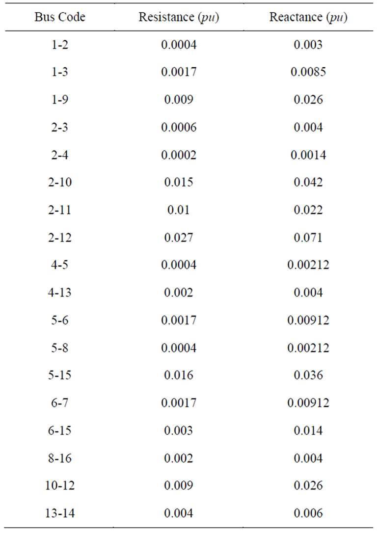
Table A.2. Line data of Alex. 66 kV network.