Smart Grid and Renewable Energy
Vol.1 No.3(2010), Article ID:3323,10 pages DOI:10.4236/sgre.2010.13016
A Study of DTC-Power Electronic Cascade Fed by Photovoltaic Cell-Three-Level NPC Inverter
![]()
1Instrumentation Laboratory, Houari Boumediene University of Science and Technology, Algiers, Algeria; 2Electrical Engineering Department, Polytechnic National School, Hassen Badi, Algiers, Algeria; 3Robotics Laboratory, Houari Boumediene University of Science and Technology, Algiers, Algeria.
Email: {imessaif, saadia_nadia}@hotmail.com, emberkouk@yahoo.fr,
Received October 4th, 2010; revised October 27th, 2010; accepted November 5th, 2010
Keywords: DTC, Switching table, NPC three-level inverter, Photovoltaic, Neutral point potential, Redundant states
ABSTRACT
This paper proposes a high performance three-level inverter Neutral Point Clamped (NPC) structure for photovoltaic system. The proposed configuration which can boost the low voltage of photovoltaic (PV) array, can also convert the photovoltaic DC power into high quality AC power. Attention has been paid to the problem of neutral point potential variation. In this way, a Direct Torque Control (DTC) technique has been applied and the estimated value of the Neutral Point Potential (NPP) is used, which is calculated by motor currents. This control strategy uses the redundancy presented by the inverter for selecting appropriate switching state through a switching table to achieve the control of NPP. This study shows the effect of the stability problem of the DC voltages and good static and dynamic performances were obtained in simulation of the proposed cascade “photovoltaic cell-three-level NPC VSI-induction motor”.
1. Introduction
As conventional energy sources are dwindling fast with a consequent rise in cost, considerable attention is being paid to other alternative sources. Solar energy which is free and abundant inmost parts of the world has proven to be an economical source of energy in many applications. The photovoltaic process is a technology in which radiant energy from the sun is converted to direct current (DC) electricity. A renewable energy application such as photovoltaic (PV) system [1] is the most promising energy and has been widely used for a few decades. This latter is becoming increasingly important as a renewable source since it offers many advantages such as incurring no fuel costs, not being polluting, requiring little maintenance, and emitting no noise, among others.
On the one hand, an important advance is realized by the power electronic technology and on the other hand the power switches used in the structures of converters are able to switch more quickly. Consequently, new structures have emerged based on multilevel topology [2]. These inverters are able to generate better output quality, and should be used, to reduce the maximum voltage stress and switching frequency across the switches but also have many more available vectors, the output voltage can take several discrete levels of equal magnitude. Also, it increases with the number of inverter levels, and the use of high speed semiconductors becomes possible for high power applications. The most popular topology is the three-level inverter, first proposed as a “neutralpoint-clamped inverter” [3]. This three-level topology, however, requires equally two divided input voltage sources. For those applications, that do not have the divided input voltage sources, a series connected capacitor bank is a popular implementation.
The operation with unbalanced voltage in the DC bus affects the converter performance due to the generation of uncharacteristic harmonics in the inverter output voltage. In order to maintain the equal voltage division, it is critical to control Neutral Point Potential (NPP). A large amount of research has looked at solving this problem [2,4,5]. Meanwhile, the NPP has closed relations with the vectors that can be implemented by different switch combinations. Therefore, analysis for the variation of Neutral Point Potential is required and a control method for maintaining the NPP should be developed.
The most extended control system for three-level inverters is the application of the Direct Torque Control (DTC) strategy [6,7]. It was introduced to give a fast and good dynamic torque response. In principle, DTC method is based on instantaneous space vector theory. By optimal selection of the space voltage vectors in each sampling period, DTC achieves effective control of the electromagnetic torque and the stator flux on the basis of the errors between theirs references and estimated values. It also regulates the NPP through the information on the voltage capacitors. It is possible to directly control the inverter states through a switching table, in order to reduce the torque and flux errors within the desired bands limits and also the NPP variations.
2. DTC Principles
A block diagram of a basic DTC controller is given in Figure 1. In principle, Direct Torque Control is a direct hysteresis stator flux and electromagnetic torque control scheme, which triggers one of the available discrete voltage vectors generated by a VSI to keep the stator flux and torque within the limits of two predefined bands. The correct application of this principle allows a decoupled control of flux and torque [8].
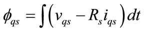
In Direct Torque Control schemes, the magnitude of the stator flux linkage vector is controlled which further can be decomposed to its orthogonal components expressed at a stationary reference frame as:
 (1)
(1)
 (2)
(2)
where fds and fqs are the d-axis and q-axis stator flux linkage components.
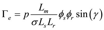
The torque could be expressed in terms of stator flux, rotor flux and the angle γ between them.
i.e.,
 (3)
(3)
In formula (3) , Lm is the magnetizing inductance of the motor, and Ls and Lr are the stator and rotor inductance, respectively.
In general, rotor flux changes much more slowly than that of the stator. If samling period Te is short enough, and the stator flux is assumed to be constant, the torque can be rapidly changed by tuning γ in the desired direction (Figure 2). The angle γ can be easily changed by the appropriate space voltage vector.
If for simplicity, it is assumed the stator voltage drop Rsis is small and neglected, than the stator flux variation can be expressed as:
 (4)
(4)
As shown in formula (4), the stator flux variation is nearly proportional to volatge vector, as the sampling period is constant, and stator flux space vector will move fast if non-zero switching vectors are applied.
Being p the number of pole pairs, the original torque equation (equation (3)) has another presentation as:
 (5)
(5)
3. DTC Using a Three-Level NPC Inverter
The advantage of the three-level NPC Voltage Source Inverter (VSI) can summarized as follows: voltage across the switches is only half of the DC bus voltage, switching losses are cut in half with reduced harmonics of output waveforms for the same switching frequency, and power rating increases. However, the drawbacks of this kind of inverter include complex control, more devices and the charge balance problem of the NPP.
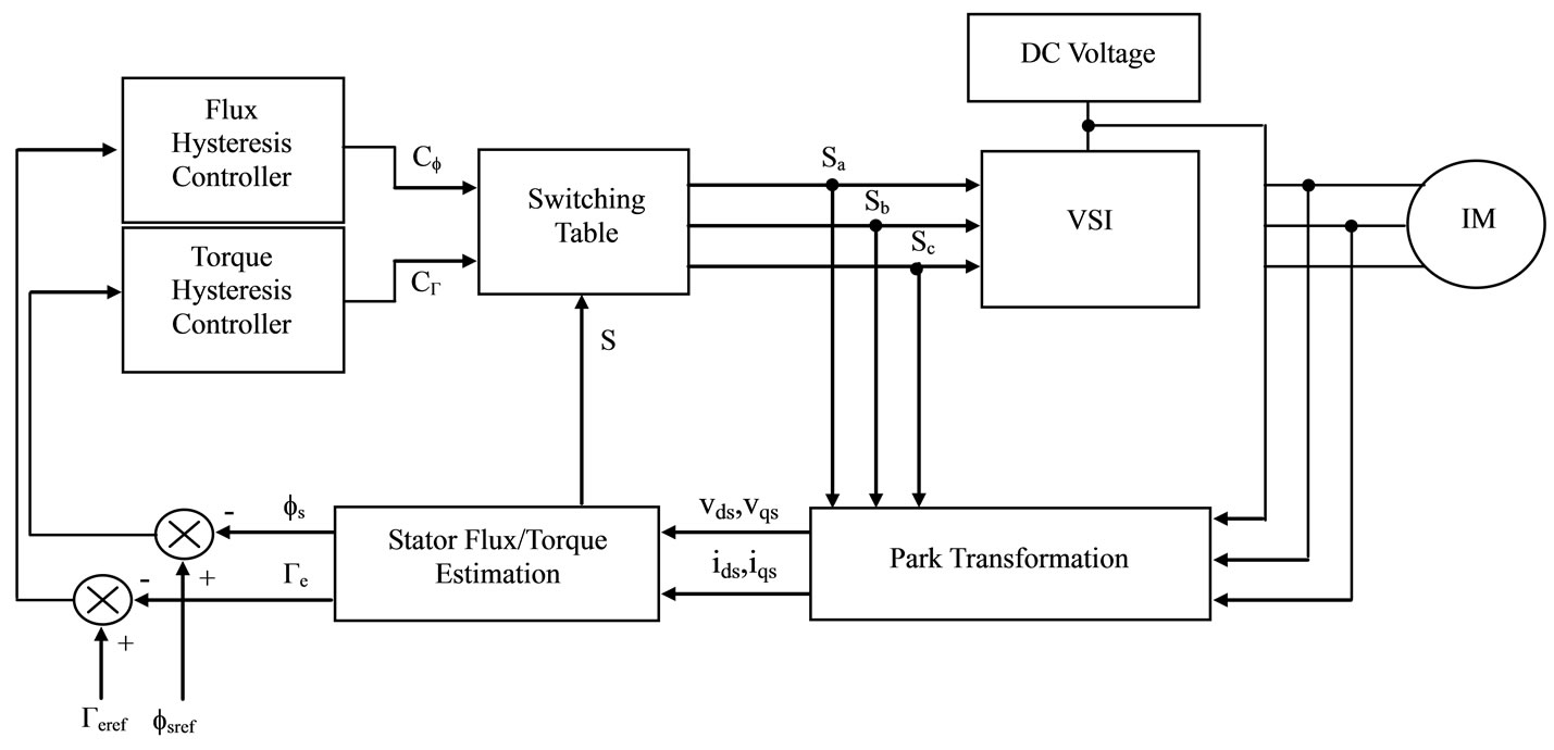
Figure 1. Basic configuration of DTC scheme.
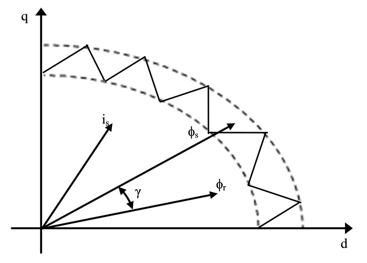
Figure 2. Stator and rotor fluxes and stator current vectors.
The schematic diagram of a three-level NPC VSI is shown in Figure 3. It built-up of twelve switches, each one with its freewheeling diode and six power diodes that allow the connection of the phases outputs to the middle point o. As in the two-level VSI, the necessary conditions for the switching states of the three-level VSI are that the DC link capacitors should not be shorted and each bridge leg has three status including p, o and n. A switching control Si can be defined and expressed as:
Si = n Þ (Si1, Si2, Si3, Si4) = (0,0,1,1)
Si = o Þ (Si1, Si2, Si3, Si4) = (0,1,1,0)
Si = p Þ (Si1, Si2, Si3, Si4) = (1,1,0,0)
where i = a, b, c.
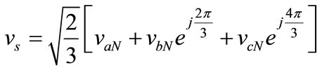
Therefore, the stator voltage vector in the Park stationary plane (d,q) might be written as follow:
 (4)
(4)
where vaN, vbN and vcN represent the stator simple voltages.
Relatively to the two-level inverter which is only capable to produce 8 voltage vectors [9], a three-level inverter has 27 switching states as Figure 4 showing. If voltages of two capacitors are equivalent, some switching vectors are overlapped and there are 19 effective vectors.
According to the magnitude of the voltage vectors, we divide them into four groups: The large vectors are the vectors that all of the three switches are connected to either of p or n potentials except in the case of all three being connected at the same point. The medium vectors are the ones that have only one phase connected at neutral point and other two switches are connected to p and n potential each other. The small vectors are those vectors that have two switches connected at the same point, the remaining one is connected at another adjacent point.
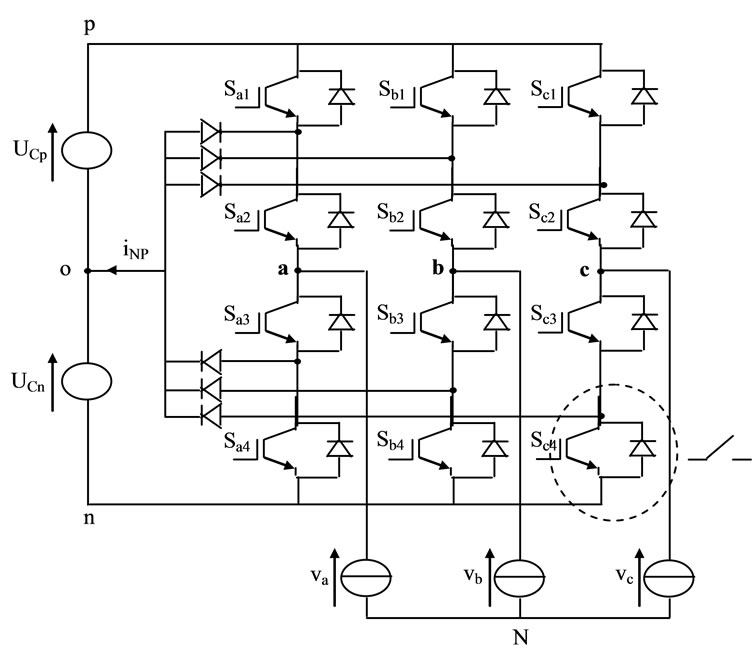
Figure 3. Schematic diagram of a three-level NPC VSI.
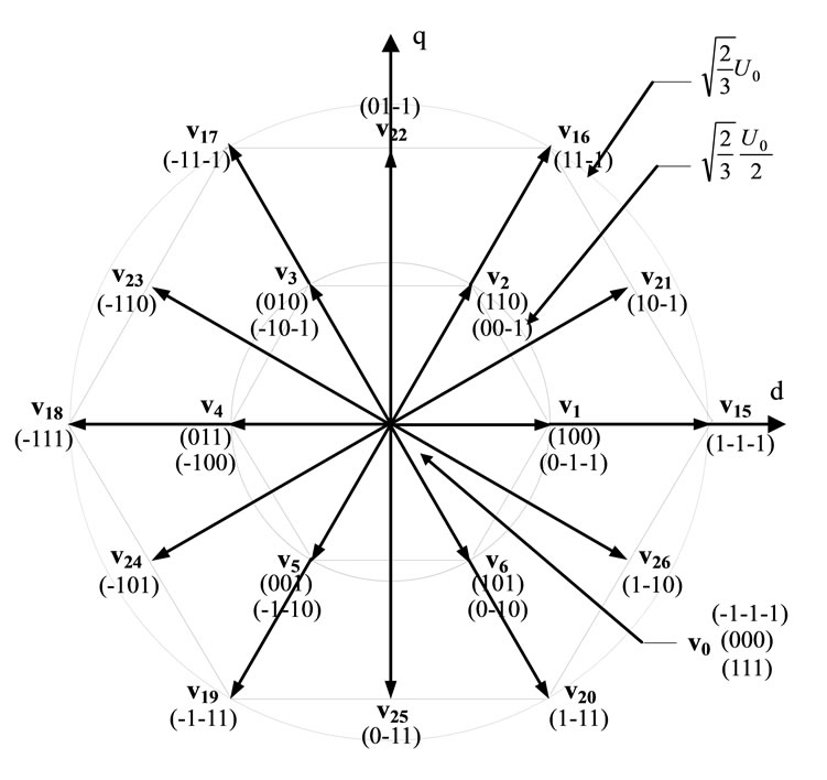
Figure 4. Space voltage vectors with theirs switching states.
The zero vectors are the vectors that have all three switches connected to same point. The zero vectors do not have output voltage. Besides, some space vectors as small vectors are gotten with two different switches configurations (as example poo and onn).
Keeping in mind the simplicity of DTC, the same principle, as explained in Section 2, can be applied when a three-level inverter feeds the induction motor.
For the regulation of the field, let the variable εf be located in one of the two regions to which a variable Cf in two states is associated. The flux control is made by two-level hysteresis controller and Cf defines the action wished on the behaviour of the field. Also, for the regulation of the electromagnetic torque, a high level performance torque control is required. To improve the torque control let of the mismatch εΓ to belong to one of the five regions, to which a variable CΓ in five states is associated. The torque control is then controlled by a hysteresis controller built with two lower and two upper known bounds and CΓ defines the action wished on the behaviour of the torque.
Several switching tables for three-level inverter are presented in literature [10,11]. Then, an optimal table for the inverter selector has been developed [12], to achieve an accurate control. The flux position in the (d,q) plane is quantified in six (6) sectors S of 60˚ degrees starting with the first sector situated between −30˚ and 30˚. The numbers in the table for inverter state are written according to Figure 4. In order to simplify, the mechanical rotor speed will be considered when assigning the voltage vectors needed at each one of those sectors. The speed of the stator flux linkage vector is given by the modulus of the applied voltage vector. Thus, the voltage vectors will be chosen according to the rotor speed. Voltage vectors with low amplitude will be chosen for lower speeds. Taking into account the available voltage vector amplitudes in a three-level inverter, two different tables have been used. Each table corresponds to a specific speed range, as shown in Table 1. Note that the zero vectors are always selected to minimize the commutation number of switches.
4. Cascade of Photovoltaic Generators-Three-Level NPC VSI-IM
In this section, we propose a cascade constituted by two photovoltaic generators, a three-level NPC VSI which feeds an induction motor (Figure 5).
The building block of the PV array is the solar cell, which is basically a PN semiconductor junction that directly converts light energy into electricity. Currently, various numerical models are in use by engineers investigating different aspects of photovoltaic technologies under different weather conditions (light and temperature) [13]. In this paper, we present the model with one exponential (diode) [14,15]. The equivalent electric diagram is shown in Figure 6.
The characteristic equation for the output current Ipv and voltage Vpv of a solar cell is given as follows:
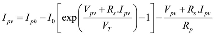 (5)
(5)
where Iph is the photocurrent depends on the solar radiation and the cell temperature and I0 is the cell reverse saturation current varies with temperature. Rs and Rp are respectively the series and the shunt parasitic resistances.
VT = (nKT)/q is the thermal voltage, where K is the
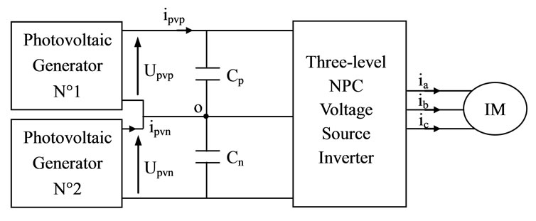
Figure 5. Photovoltaic generators—Three level inverter —Induction motor cascade.

Figure 6. Electrical Scheme of a photovoltaic cell with two diodes.
Boltzmann’s constant, q the charge of electron, n the ideality factor and T the cell temperature.
Figure 7 gives the current-voltage (I-V) and powervoltage (P-V) characteristics of a PV module for different values of solar radiation and temperature. The short circuit current is clearly inverse dependence to the temperature (Figure 7(c)): an increase in temperature causes a reduction of the open-circuit voltage (when sufficiently high) and also more maximum output power.
On the other hand, the variation of irradiance affects visibly the short circuit current and low voltage on open circuit, therefore the variation of MPP is proportional to the irradiance (Figures 7(a) and (b)).
This control system has been tested by simulation. It is considered an induction motor with the characteristics reported in Table 2. All simulations have a sample time for the control loop of 100 μs, the voltage of the DC bus is 514 V.
Figure 8 presents respectively the simulation results of the capacitors voltage (Ucp and Ucn) and the neutral current variations (iNP). The DC link has a capacity of 3.9 mF and theirs voltages are unbalanced. The neutral point potential is rising significantly and causes over voltages across the semi-conductor switches. These fluctuations affect the motor performances. Therefore, analysis for the variation of NPP is required and a control method for maintaining this potential point should be developed.
5. Analysis of Neutral Point Potential
This type of inverter has an inherent problem of NPP unbalance. As the level increases, the problem becomes more complicated. In this case, this study concentrates on
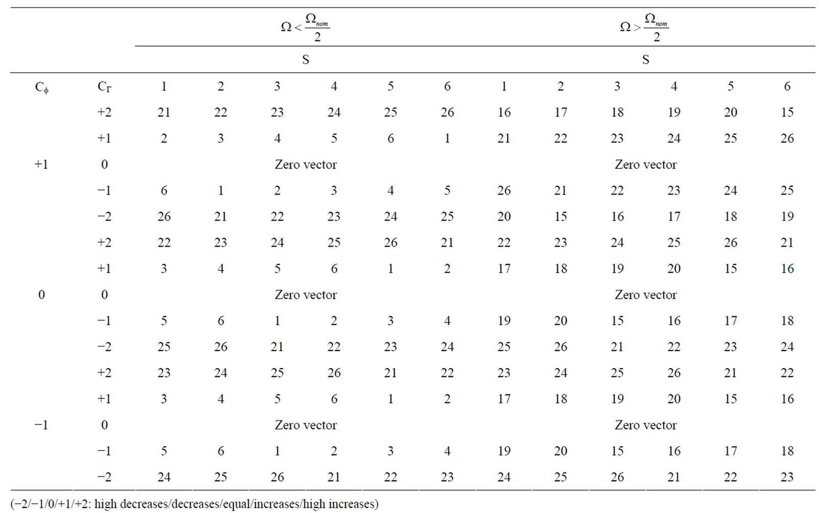
Table 1. Switching table.
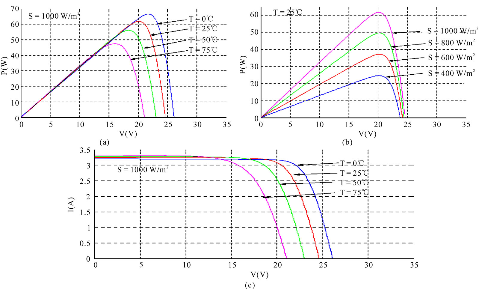
Figure 7. Solar radiation and temperature influences on the P-V ((a),(b)) and I-V (c) characteristics.
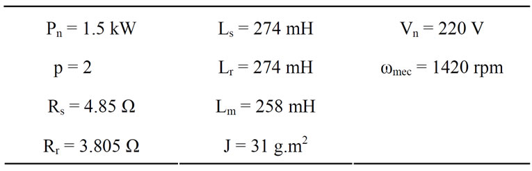
Table 2. Induction motor characteristics.
modelling the properties of DTCs with respect to the current in the neutral point. The direct reason for the NPP unbalance is due to the current flow from/to the neutral point. As mentioned above, the NPC three-level inverter has redundant states. Thus, some discrete voltage level can be obtained by more than one switching state. As the voltage evolution for a given capacitors will be different for each state as shown in this section, this redundancy permits to control the capacitors voltages while the requested vector voltage is supplied [16].
The large vectors and the zero vectors do not change the voltage of neutral point. For the medium vector, there is only one vector for a specific direction. The line current flows through the neutral point for a given vector and the NPP is then affected. The compensation of voltage capacitor balance has to be given to the next medium vector because this vector could flow opposite current from the capacitor bank.
Figure 9 shows an example of one small vector given by two different switching combinations. Both combinations produce the same output voltage v1, but when the first combination is applied, the current flows into the neutral point and produces discharge in the capacitor Cp and with the second it follows out and produces a charge in the same capacitor. This property provides the freedom to control the voltage of the neutral point.
Based on this property, a control strategy will be developed and applied to a three-level NPC VSI. In Table 3, some switching states and the corresponding capacitors voltage evolution are presented. The capacitor volt-
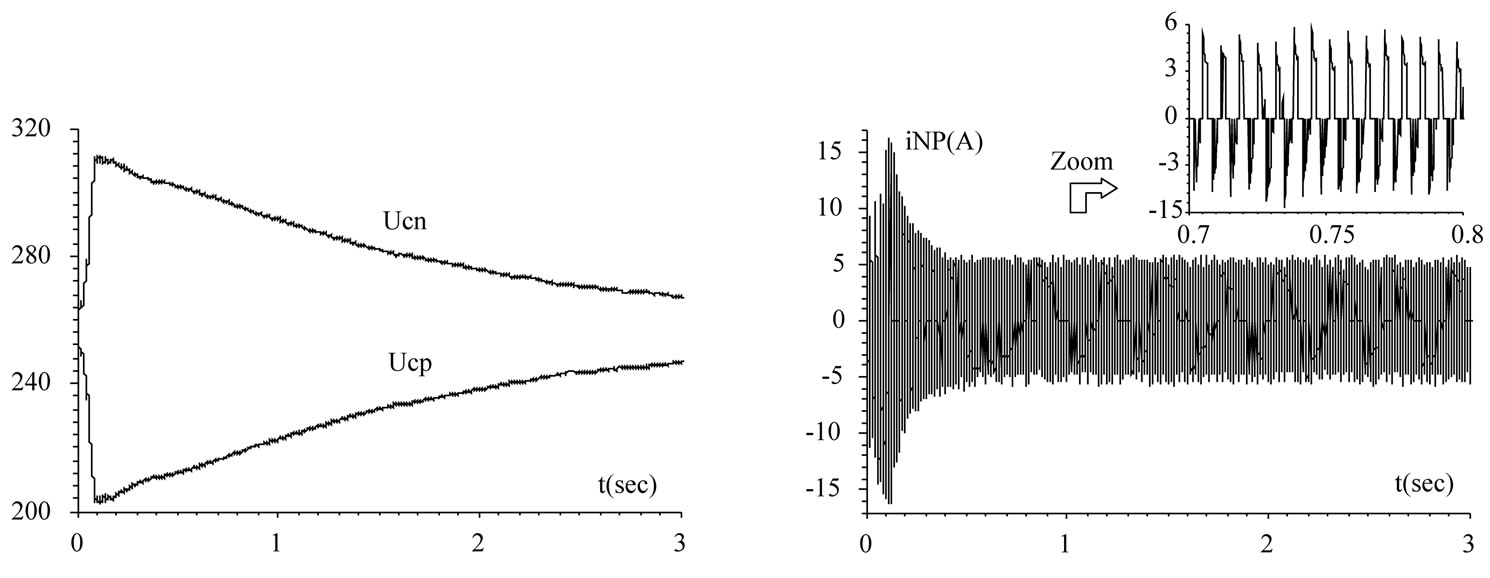
Figure 8. DTC without control of NPP: deviation of capacitor voltages and neutral point current.
 (a) (b)
Figure 9. Two different switching combinations of vector v1, (a) (poo); (b) (onn).
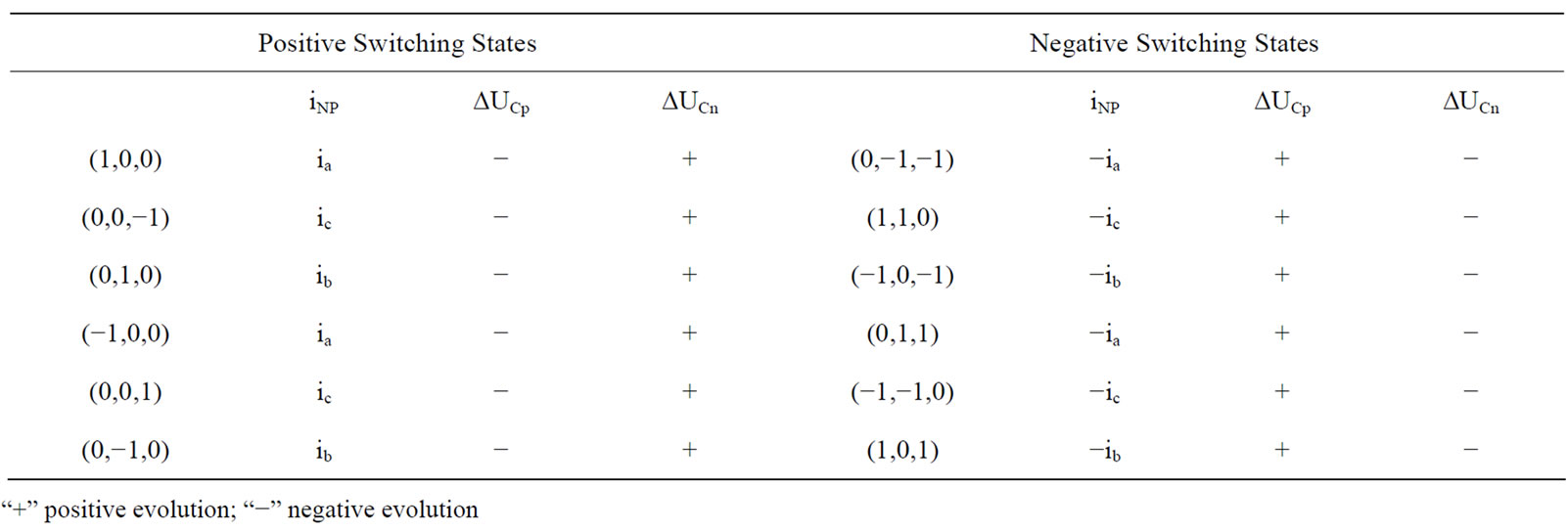
Table 3. Effect of small vectors on neutral current and voltage capacitor variation.
age evolutions are different at each one of those switching states. Thus, using as inputs the required voltage vector, the actual state of the capacitor voltages and the current direction in the neutral point, a control algorithm has been defined. Then, the inverter will be controlled by the switching state assuming the requested discrete voltage vector and the needed capacitor voltage evolutions. The diagram of the control algorithm is shown at Figure 10.
In order to realize safe operation of this topology as the three-level inverter, an appropriate method needs to be found for keeping NPP as half of the input voltage.
The relation between the inverter output line voltage and the voltage across each capacitor are defined by [15]:
 (6)
(6)
where Sabp = Sap – Sbp, Sabn = San – Sbn…
Sap, Sbp, Scp, San, Sbn and Scn represent the inverter switching functions for the positive (e.g. Sa1, Sa2) and negative (e.g. Sa3, Sa4) switches.
The voltage of Cp and Cn in terms of the full DC link voltage and the neutral point error voltage εNP are written as:
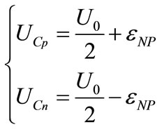 (7)
(7)
The equation that relates the currents ip and in with the inverter output currents ia, ib and ic is written as follow:
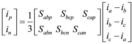 (8)
(8)
But Cp = Cn = C and the neutral current, iNP, is equal to
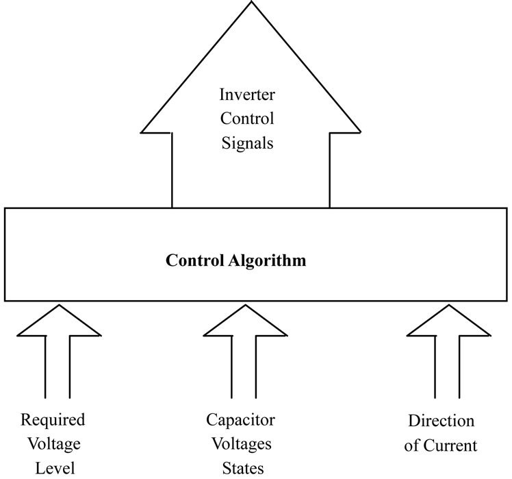
Figure 10. Control algorithm block diagram.
ip + in. We can derive equation (9), which defines the dynamic relationship between iNP and .
.
 (9)
(9)
Finally, combining these equations, a dynamic equation describing the three-level switching network is developed.
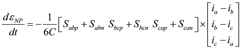 (10)
(10)
The DTC technique is achieved by alternately selecting one of the available voltage vectors to keep stator flux and electromagnetic flux near the corresponding references and also stabilize the NPP variations. The selection table generates pulses (Sa, Sb, Sc) to control the power switches in the inverter.
The three-level DTC strategy with control of the NPP has been tested by simulation in a speed control loop. A constant load torque equal to nominal value has been applied. Simulation results are shown in Figures 11 and 12. The PI controller speed gains are given by kp = 0.83 and ki = 5.82 and the amplitudes of hysteresis bands are fixed to ∆fs = 3%, ∆Γe1 = 2.7%, ∆Γe2 = 3%.
In Figure 11, the voltage capacitors Ucp and Ucn are shown. The inverter control algorithm keeps the capacitor voltages between the permitted limits, the slight unbalance, with regard to the exact expected values, is due to the allowed tolerance of ± 3% around the exact value and the NP current has a mean value practically null. In addition, the requested space voltage vector, demanded by the DTC strategy, is assured as shown by the line voltage vab. Thus, if compared with a two-level DTC strategy [9], the dv/dt applied to the motor terminals is greatly reduced.
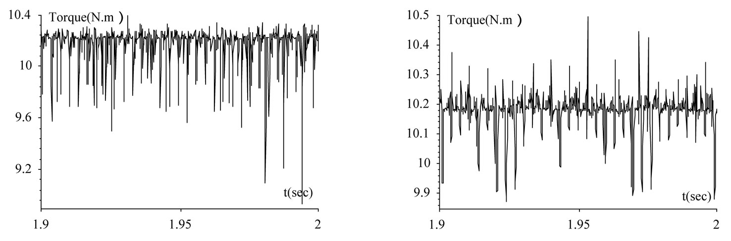
Furthermore, it is possible to reduce the torque ripple amplitude by approximately of 2 when compared to a two-level DTC strategy, as shown in the next figure. The torque is kept at its reference value as shown by the torque error (Figure 12(b)).
Besides controlling the electromagnetic torque, DTC also controls the stator flux, whose variations are shown in Figure 12(c). We note these low ripple and rapid response.
Finally, the speed response with its reference is shown for nominal load conditions of 10 N.m. (Figure 12(d)). The figure shows that the motor starts smoothly and the speed tracks the command with small overshoot and with nearly zero steady-state error.
6. Conclusions and Perspectives
In this work discusses about the performances of the cascade of the photovoltaic panels with three-level inverter NPC structure. The Direct Torque Control strategy provides an easy way to perform the neutral point potential. A precise estimation of the NPP is used to select the appropriate switching state of inverter as shown in switching table. The proposed method provided stabilization of Neutral Point Potential variation and improvement of the motor current waveform. Furthermore, the Neutral Point Potential voltage could be kept to small variation by choosing relatively large capacitors for the capacitor bank.
The effectiveness of a control algorithm is investigated via simulations, it has been shown that the cascaded with three-level inverter is a suitable choice for photovoltaic systems applications. The results show that the performances obtained are full of promise to be using this inverter in renewable energy.
However, the implementation of this control strategy


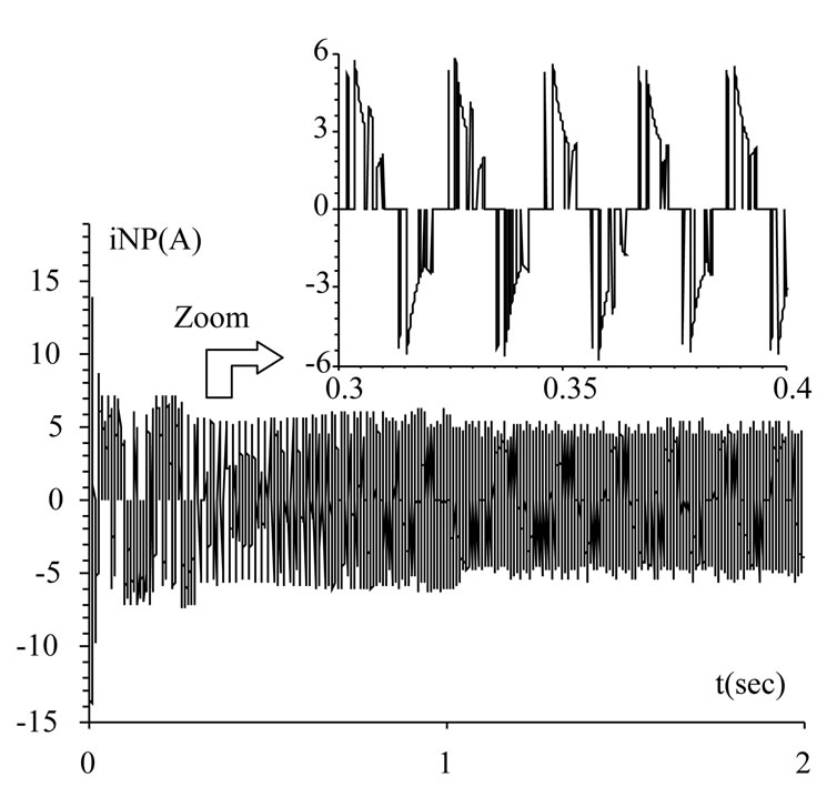
Figure 11. DTC with control of NPP: difference between voltages capacitors, stator line voltage, neutral point current.
 (a)
(a)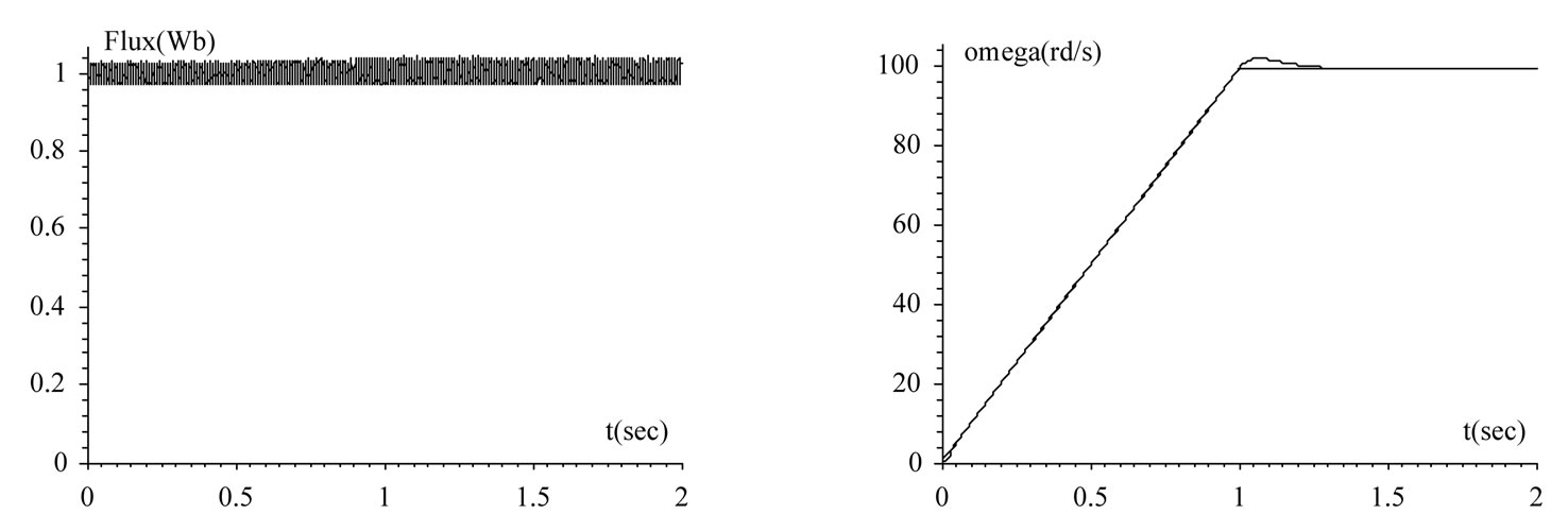 (b)
(b)
Figure 12. DTC Performances: (a) Zoom EM torque two-level (b) Three-level (c) Stator flux (d) Mechanical speed.
requires a great number of ROM, used to store the switching table. The usage for example of the Artificial Neural Network structure as switching vector selector can improve this problem.
REFERENCES
- F. Blaabjerg, R. Teodorescu, M. Liserre, and A. V. Timbus, “Overview of Control and Grid Synchronization for Distributed Power Generation Systems,” IEEE Transactions on Industrial Electronics, vol. 53, no. 5, 2006, pp. 1398-1409.
- P. Purkait and R. S. Sriramakavacham, “A New Generalized Space Vector Modulation Algorithm for NeutralPoint-Clamped Multilevel Converters,” Proceedings of the Progress in Electromagnetics Research Symposium, Cambridge, 2006, pp. 330-335.
- A. Nabae, I. Takahashi and H. Akagi, “A New Neutral Point Clamped PWM Inverter,” IEEE Transactions on Industry Applications, vol. IA-17, no. 5, 1981, pp. 518- 523.
- F. Bouchafaa, A. Talha, E. M. Berkouk and M. S. Boucherit, “Stabilization of DC Link Voltage Using a Clamping Bridge In Multilevel Cascade,” Proceedings of the International Conference on Sciences of Electronic Technologies of Information and Telecommunications, Tunis, 27-31 March 2005.
- J. Holtz and N. Oikonomou, “Neutral Point Potential BalAncing Algorithm at Low Modulation Index for ThreeLevel Inverter Medium Voltage Drives,” IEEE Transactions on Industry Applications, vol. 43, no. 3, 2007, pp. 761-768.
- I. Takahashi and T. Nogushi, “A New Quick-Response and High-Efficiency Control Strategy of Induction Motor,” IEEE Transactions on Industry Applications, vol. 22, no. 5, 1986, pp. 820-827.
- A. Campeanu, M. Badica and V. Iancu, “Direct Torque and Flux Control of Saturated Induction Machines,” Proceedings of the International Symposium on Advanced Electromechanical Motion Systems (Electromotion), Lausanne, 27-29 September 2005.
- A. L. Mohamadein, R. Hamdyn and M. Gadoue, “A ComParison between Two Direct Torque Control Strategies for Flux and Torque Ripple Reduction for Induction Motors Drives,” Proceedings of the Ninth International Middle East Power Systems Conference (MEPCON’2003), Shebeen Al-Koum, Egypt, 16-18 December 2003.
- I. Messaïf, E. M. Berkouk and N. Saadia, “Direct Torque Control for Induction Machines Using Neural Networks,” The Archives of Control Sciences, vol. 17-LIII, No. 1, 2007, pp. 5-16.
- X. del Toro, S. Calls, M. G. Jayne, P. A. Witting, A. Arias and J. L. Pomeral, “Direct Torque Control of an Induction Motor Using a Three-Level Inverter and Fuzzy Logic,” Proceedings of Industrial Electronics, International Symposium, vol. 2, No. 4-7, 2004, pp. 923-927.
- I. Messaïf, E. M. Berkouk and N. Saadia, “Selection of Voltage Switching Tables DTC of Induction Motor Driven by Three-Level NPC VSI,” Proceedings of the First Electrical Engineering Conference 2007 EE’07, Aleppo, Syria, 26-28 June 2007.
- I. Messaïf, E. M. Berkouk and N. Saadia, “Ripple Reduction in DTC Drives by Using a Three-Level NPC VSI,” Proceedings of the IEEE International Conference on Electronics Circuits and Systems, Marrakech, 11-14 December 2007, pp. 1179-1182.
- B. Multon, et al., “Analysis and Experimental Validation of Various Photovoltaic System Models,” Proceedings of the 7th International ELECTRIMACS’2002 Congress, Montréal, 2002, pp. 1-6.
- G. Saravana, P. Srinivasa Rao, A. Karthikeyan and C. Nagamani, “Single-Stage Sine-Wave Inverter for an AutoNomous Operation of Solar Photovoltaic Energy Conversion System,” Renewable Energy an International Journal, Vol. 35, No. 1, 2010, pp. 275-282.
- G. Araujo, E. Sanchez and M. Marti, “Determination of the Two Exponential Solar Cell Equation Parameters from Empirical Data,” Solar Cells, Vol. 5, No. 2, 1982, pp. 199- 204.
- N. Celanovic, “Space Vector Modulation and Control of Multilevel Converters,” Ph.D. Dissertation, Faculty of the Virginia Polytechnic Department, Virginia, 2000.