Energy and Power Engineering
Vol.11 No.07(2019), Article ID:94099,24 pages
10.4236/epe.2019.117017
Performance Optimization of Diesel Generators Using Permanent Magnet Synchronous Generator with Rotating Stator
Mohammadjavad Mobarra1*, Mohamad Issa1, Miloud Rezkallah2, Adrian Ilinca1
1Wind Energy Research Laboratory (WERL), Université du Québec à Rimouski, Rimouski, Canada
2Electrical Engineering Department, Ecole de Technologie Supérieure (ETS), Montréal, Canada

Copyright © 2019 by author(s) and Scientific Research Publishing Inc.
This work is licensed under the Creative Commons Attribution International License (CC BY 4.0).
http://creativecommons.org/licenses/by/4.0/


Received: June 16, 2019; Accepted: July 28, 2019; Published: July 31, 2019
ABSTRACT
One of the solutions to reduce fuel consumption of diesel generators (DG) is to adapt the rotational speed to mechanical torque of the crankshaft. When load power decreases, a reduction in both mechanical torque and rotational speed of the diesel engine will maintain the combustion efficiency near the levels of the nominal regime. Accordingly, the generator itself should operate at a variable speed which normally requires power electronics converters. In this paper, we are exploring a new generator concept that uses a stator rotating in opposite direction to the rotor such as the relative velocity between the two components remains constant when diesel engine slows down. The stator itself is driven by a compensator synchronous motor (CM) such as the relative velocity of the rotor is constant, eliminating as such sophisticated power electronics. The model developed for the synchronous machine with a rotating stator is based on Park’s transformation. This new concept was modelled using MATLAB software. Experimental analysis has been conducted using a 500-kW diesel GENSET equipped with a permanent magnet synchronous generator (PMSG). The numerical and experimental results are in good agreement and demonstrate that fuel consumption is reduced with a rotating-mode stator for PMSG during low electrical loads.
Keywords:
Diesel Generator, Park Transformation, Rotating Stator, Fuel Optimization, Rotating Reference Frame

1. Introduction
Regardless of all improvements in renewable energy sustainability, various applications and communities are still dependent on diesel generators (DG) to meet their energy demand. Durability and reliability of DG made this application popular compared to other power sources in remote sites, with electric load oscillations and/or facing difficult weather conditions [1] . In Canada, there are numerous remote areas with limited accessibility especially during winter months, where diesel engines (DE) are used to meet electricity demand such as telecommunication stations, mines and villages. In these sites, diesel engines are working non-stop even during low-load demand which results in important greenhouse gases (GHG) emissions and other negative consequences. For instance, high energy costs and environmental risks and impacts are associated with fuel transportation and storage in these remote areas [2] [3] [4] [5] [6] . Diesel engine and generator speed are synchronized. The crankshaft of DE is coupled to the rotor of the synchronous generator (SG). SG needs to rotate at its nominal speed to produce reliable electricity either in full load or low load. Thus, the DE, coupled with SG rotor, should inevitably rotate at SG’s nominal speed [7] . The variation of diesel engine speed results in poor power quality production. Electronic devices and electric apparatuses are sensitive to and affected by poor power quality and high harmonics [8] . Therefore, it is critical to control the DE speed to produce a constant frequency and voltage. Fuel governor is a mechanical device that adjusts the fuel injection to maintain the nominal speed when load power and associated torque vary. However, this controller accuracy is limited, and the adaptation of DE speed is relatively slow during electrical load oscillations [9] . Consequently, the diesel engine runs at fixed speed at all regimes with its best fuel efficiency at nominal power. When DE operates at different regimes than nominal, its efficiency is reduced, sometimes significantly. Especially at low regimes, poor fuel efficiency and high maintenance cost affect significantly DG operation [10] [11] [12] . Specific fuel consumption (SFC) rate for DE is also affected by other operation parameters such as appropriate maintenance, loads and ambient temperature [13] . Therefore, a major inconvenient of operating DE at fixed speed is that its efficiency is optimal at nominal power but decreases sharply at lower regimes [14] . One solution to improve operation efficiency of the DE is to adapt its rotational speed to the load power (torque of the generator) such as to operate at maximum efficiency at all regimes [7] .
This means that is necessary to reduce the rotational speed of the DE at lower regime and, consequently, have a diesel generator that can operate at variable speed.
The “classic” solutions to adapt the DE speed to required torque from the generator is to use power converters [15] [16] or variable speed gearbox [12] [17] . To decrease the fuel consumption, the synchronous generator should operate at variable speed, the one that is optimal for the diesel engine. Sophisticated electrical power converter could compensate the voltage and power output when the synchronous generator operates at variable speed. However, the other way to provide desired torque for generator is to use complicated mechanical gearbox [17] . Continuously variable transmission (CVT) enables the generator to produce constant frequency while the engine revolution per minute (rpm) varies.
CVT provides adequate mechanical torque for electrical generator while it is transferring rotational energy from diesel engine. In this paper, we explore a new solution to operate the diesel generator at variable speed using a synchronous generator with a rotating stator [18] [19] [20] . The stator of this new generator rotates in opposite direction to the rotor such as the relative velocity between the two components remains constant when diesel engine slows down. The stator itself is driven by a compensator synchronous motor (CM) such as the relative velocity of the rotor is constant to avoid any harmonics or poor power quality and to eliminate sophisticated power electronics or complicated variable transmission. This technology could lead the system to provide a better fuel efficiency profile by running diesel engine at its most ideal throttle. As a result, this causes the combustion chamber to avoid bore glazing issue and increase diesel engine life [13] .
In the paper, we will present the new system, then develop a model for the synchronous machine with a rotating stator based on dq-transformation. Numerical modeling with MATLAB and experimental analysis conducted for a 500-kW diesel generator with rotating stator demonstrate the fuel consumption reduction during low electrical loads.
2. Application of Variable-Speed DG and Model
2.1. System Description
The major aim of this project is to reduce diesel engine speed at low regimes to maintain higher fuel consumption efficiency. In the meantime, the synchronous generator needs to rotate at its synchronous speed to produce high-quality power whatever the load. In conventional GENSET system, the diesel engine crankshaft connected to the rotor of the SG runs at 1800 rpm to produce 60 Hz frequency [17] .
Inevitably, this research has developed the electrical generator in a way to compensate the ideal speed for itself. In this new SG concept, an innovative rotating-mode stator design has introduced to keep total synchronous speed constant while DE speed reduces to its ideal regime. The new idea has focused on the stator part of PMSG. Thus, obtaining nominal speed for the electrical generator is not limited to rotor speed anymore. Synchronous speed could achieve by controlling the compound speed (Rotor and Stator Speed). If rotor speed reduces due to an ideal mechanical torque from DE, adjustable stator speed could compensate the ideal speed for SG.
Synchronous speed for SG achieves by rotating stator part in a reverse direction of rotor direction using a synchronous motor (compensator motor) installed above the PMSG casing. This method optimizes DE performance by reducing the speed to its nominal regime. Moreover, reducing fuel consumption of DE could also achieve by controlling DE crankshaft power, which mostly connected directly to the rotor of PMSG.
This interesting idea decreases maintenance fee by reducing mechanical stress on DE crankshaft system, extend diesel-engine life and optimize greenhouse gases (GHG) emission profile [21] . Figure 1 illustrates the GENSET schema using non-stationary synchronous stator. One side of SG has coupled with compensator motor and the other side has fixed to DG (crankshaft). In this project CM rotate at anticlockwise direction to compensate the required speed for PMSG.
2.2. Rotating-Stator Concept
Based on the explanation before, this research proposes a rotatory stator for a PMSG structure and simultaneously tries to follow the electrical standards limitation regarding harmonics, voltages and currents. In this application, PMSG has developed by a series of separate bearings installed on the external body of the stator end and it was tried to make it rotatory with minimum friction. Regarding conventional SG structure, stator is fixed with machine casing [22] . But in this research both rotor and stator are rotating around the same axis. Moreover, the stator windings and connections remain the same as the conventional one. A pulley has attached at the end of synchronous machine casing and connected to the stator. Therefore, by applying dynamic force on the pulley, stator starts to rotate at our ideal direction and speed. 75-kW synchronous motor (compensator motor), is mounted on the body of 500-kW generator and coupled by the stator pulley using timing-belt. In this study, CM has adjusted to rotate the stator in the reverse direction of rotor rotation (Rotor has already coupled by the crankshaft of DG). The compensator motor is supplied by the PMSG production during low load connection. Thus, the small fraction of GENSET production is consumed by itself (compensator motor). Finally, this technology helps DE to reduce the speed to its ideal regime whereas SG total speed kept constant by the help of CM.
Figure 2 illustrates the primary portrait of Non-Stationary stator connected to the synchronous motor via timing belt. One side of SG connected with compensator motor and the other side (rotor) affixed to DG (crankshaft). In terms of different regimes, controlling synchronous speed ( ) for variable speed GENSET application is one of the major challenges in electric production [23] . Variable speed stator technology for SG, leads this application to achieved synchronous speed without any interference on DE performance or using power converters. In this new structure, both rotor and stator rotate around the same axis but in different directions. Stator speed rotation ( ) is in a reverse direction of rotor speed rotation ( ) to compensate the necessary speed for producing synchronous speed. Therefore, we can write the primary assumption equation as follow:
Harmonic treatment and low power quality compensation need sophisticated power converters in case of variable speed production. Accordingly, 1800 rpm is

Figure 1. Variable Speed Diesel Generator.

Figure 2. Rotating-Mode Stator Scheme for PMSG.
necessary for PMSG to produce 60 Hz frequency [16] . Non-Static stator technology operates in a wide range of speed and increases system durability by eliminating complicated mechanical gearbox or electrical converters.
2.3. Proposed SG Model Using dq-Projection
Synchronous generators are important in power generation and the need for precise modeling is critical during the time of optimization or development research [24] . The main purpose of investigation on PMSG model using park transformation is to adapt this existing model with rotating-mode stator. Existing synchronous machines in MATLAB power system library propose conventional PMSG with fix stator part. Therefore, development on synchronous machine model is necessary to adapt rotatory stator for new PMSG. The new model is capable to show SG performance using two independent mechanical inputs. This projection leads PMSG model to achieve synchronous speed using either rotor speed, stator speed or the combination of both stator and rotor speed. This model could also be use in transient state, unbalance load or line faults. Full order model of SG represents four different set of windings. Direct axis (D) represents field winding ( ) and a damper winding ( ), both are assumed on D-axis. To create symmetry, an excitation winding is also considered on the quadrature axis (q). Two damper windings and are defined on q-axis which is perpendicular with the d-axis position [25] [26] . By considering the stator and rotor windings for a sinusoidal distribution, their primary equations could illustrate in a matrix format shown as (1).
(1)
Index (s) and (r) are the stator and rotor parameters. And are the diagonal matrices for a linear magnetic system. To facilitate the calculations of salient rotor synchronous machine, rotor equations transferred to the stator side to keep both machine parts in a same reference frame [24] . Leakage flux of synchronous machine including stator and rotor flux equation is shown as (2).
(2)
( ) Inductance between the stator windings, ( ) inductance between the rotor windings and ( ) is the mutual inductance between the stator windings and the rotor windings. It is important to consider the stator windings flux variable by time due to the dynamic style of salient rotor machine. Figure 3 illustrates graphical evaluation to find the stator inductance position ( ) using salient rotor [24] [26] .
Stator inductance varies with time while salient rotor type rotating around its axis. In (3) primary flux inductance equations have expanded.

Figure 3. d-q axis Phasor Diagram.
(3)
where ( ) and ( ) are magnetic flux through winding surface and flux leakage. (P) is permeance, the path of flux (opposite of magnetic resistivity). Thus, once again for calculating stator winding inductances in a specific position and time and by simplifying equations ( ) and ( ) could evaluate as (4).
(4)
Three-phase stator winding made elements 3 × 3. In a stator inductance matrix, all diagonal elements are belonging to the self-mutual inductances and leakage plus mutual. On the other hand, off-diagonal inductances are mutual inductances between two different sets of windings. They are negative due to 120-degree phase difference between each axis and regarding flux effect of one winding into another [24] . Back to equation (2), all matric elements of inductances calculated from (3) and (4). In this step, all parameters like voltage, current, flux and the inductance of the winding leakage and their resistance should refer to the stator side. Considering the number of stator ( ) and rotor ( ) windings, Equation (5) illustrate the transformer equations.
(5)
In summation, by replacing all calculated elements for system inductances and rewriting the primary matrix equation, voltage equation obtains as (6).
(6)
From Equation (6) all calculations transferred to the stator side, but these equations are getting more complex since all phases quantities and matrix inductances are not independent from each other and they are variable with time. dq0 transformation (park transformation) is a projection to simplify the equations by transforming stator quantities from stationary reference frame to rotating dq0 reference frame, [24] . This study has used dq0 transformation that rotates at synchronous speed just for stator components because rotor components are already located at reference frame. Equation (7) shows the dq0 matrix for transferring stator components to the reference frame.
(7)
To avoid unwilling harmonics from PMSG production, providing constant 60 Hz frequency (1800 rpm) for SG is necessary. Rotating stator technology aims to achieve this speed by combining rotor and stator speed either in the same or opposite direction. Since SG rotor speed, reduced due to adapt DE speed with demanded load, another concept introduced for SG stator to rotate around the rotor axis but in reverse direction to compensate the total speed. Figure 4 indicates the developed stator structure for SG.
SG modeling carries on by presenting two independent mechanical inputs. ( ) which assumed as rotor speed and ( ) which assumed as stator speed are two independent angular velocities for PMSG. ( ) is total angular velocity which leads SG speed to achieve ideal frequency.

Figure 4. Cross Schematic of Non-Static Stator.
In this simulation for 500-kW PMSG, the stator speed has fixed to rotate at 255 rpm in opposite direction of rotor rotation. Thus, in this case the rotor speed could decrease to 1545 rpm which helps directly the DE crankshaft to reduce its speed. However, the total speed of synchronous machine has remained constant at 1800 rpm. Finally, by transferring the above equations to the reference frame using dq0 transformation, and by simplifying the calculations, voltage equations in the reference frame are calculated as (8). The first part is related to the ohmic voltage, the second part is related to the total speed rotating voltages which include two different inputs, and the third part is related to the transformer voltage.
(8)
By expanding the dq matrix calculation, the synchronous equation release as (9).
(9)
In addition, the values of leakage flux are also calculated by expanding matric as (10).
(10)
As a final step before deploying these equations into MATLAB block diagrams, flux leakages and currents are illustrated as (11). ( ) is the base electrical angular velocity to obtain primary inductive reactance during system simulation.
(11)
2.4. Numerical Modeling for Developed GENSET
Figure 5 indicates a schematic view of GENSET system using rotatory stator. Synchronous machine simulation starts with dq-transformation and continues by adding internal excitation and mechanical governor system into it. Excitation system is important in synchronous machine due to production of flux by passing current through rotor field winding. The aim of every excitation system is reliability of production under different conditions, simplicity of control, ease of maintenance and fast transient response [27] [28] [29] [30] .
This research has used automatic voltage regulation (AVR) to control the output terminal voltage of the alternator while it is connected to the loads. The principle of this excitation system is to follow the reference flux and adjust itself with it to avoid any voltage drop during load variation. However, the objective of simulation is to develop mechanical torque and governor system, where two different mechanical inputs are fixed to illustrate the effect of rotor and stator rotation.
As for total mechanical torque ( ) of synchronous machine, dual PI controller system has used to reduce the errors for total angular velocity ( ). The aim of first controller is to track DE and CM speed and reduce the possible errors by considering reference speed. DE mechanical torque out-put may vary to reach its appropriate regime. Thus, the second PI controller follows registered command for CM to rotate it at the speed which leads PMSG to reach 1800 rpm. However, in this simulation DE speed is fixed at 1545 rpm and rotates in a clockwise direction. In continue, this simulation introduces another independent in-put to compensate the require speed for SG (synchronous motor (CM)). CM speed is valued at 255 rpm and rotates in the anticlockwise direction. Therefore, developing governor system simulation to have a compound speed, leads SG to control total angular velocity either with CM or DE. Synchronous machine simulation carried out by projecting a-b-c three phase onto the d-q axis. One feature of dq-projection is the ability to specify the d-q axis speed to be any that is convenient for the user [24] . Two separate dq0 block diagrams for current and voltage are placed after dq-transformation block to produce three phase power. It is important to mention here that three phase loads are consist of purely resistive panel plus CM. Small fraction of SG production consumes by CM itself.
Figure 6 indicates the conditions on which the governor system produce appropriate . A conditional switch with three in-puts, placed to meet different regimes. First and third in-puts are for both rotor and stator speed while second in-put fixed at 1800 rpm. The function of this switch is based on total system speed.
If system speed is less than 1800 rpm then, logic switch passes third input to compensate the speed. Otherwise, switch block passes first input to reduce total SG speed. Figure 7 shows swing equations for SG, while system work under normal condition. Therefore, the relative position of rotor and magnetic axis is fixed.
In full order modeling of SG, internal excitation produces fluxes (9) and (10) in rotor windings respectively [22] . Therefore, fluxes cross stator windings to produce currents. Figure 8 shows field and quadrature current using dq0 transformation. By implementing park transformation in a balanced system, field current ( ) and quadrature current ( ) carry the same performance and characteristic of three-phase SG system during different conditions.
Table 1 has given the machine per unit values which runs by MATLAB software for 10 seconds.

Figure 5. Control schema of variable speed diesel-generator.

Figure 6. Proposed input control system.

Figure 7. Governor model with total mechanical torque.
 (a)
(a) (b)
(b)
Figure 8. (a) Schematic diagrams of quadrature current; (b) Schematic diagrams of field current.

Table 1. PMSG parameters.
3. Simulation Results
Modeling and simulation of PMSG using Non-Static stator have been carried out. Two different mechanical inputs are implemented. One input control the rotor speed and the other one, adjust stator speed. This modeling adds both values (mechanical inputs) and considers them as one for a PMSG mechanical prime mover. Results below released from MATLAB software using per unit system showing the three-phase voltages, currents, power, etc. Two different stage of loads applied in this project respectively. Initial speed of machine has fixed at 1500 rpm, as reference speed. The total speed of PMSG at rpm form is the summation of two mechanical inputs. Regarding the value of inductances in previous section, ( ) change as the rotor rotates (salient rotor). Therefore, the stator inductance values change by time. For the first scenario, the generator has connected to the 196-kW load power and the results are released in Figure 9 and Figure 10. The aim of this modeling is to simulate PMSG with rotating stator and compare the results with the experimental ones. Three-phase Sinusoidal wave forms achieved using precise AVR system and appropriate dq-abc transformation. In addition, the need for synchronous speed is critical for achieving 60 Hz frequency. Voltage and current graphs show the six times fluctuation in every 0.1 second. Time lengthen of Peak-wave for phases are equal. Three-phase balanced load formed the currents graph as below. Excitation current increases in a small fraction of second as the electrical load increase, which shows the AVR response.
Simulation of PMSG with developed governor accomplished using dq-projection. This projection reduces three-phase complicated equation into dq0-rotating axis. These difficulties are due to the mutual inductances of Rotor-Stator and variation of inductances by time. MATLAB dq0 to abc block diagrams have used to convert dq variables into three-phase voltages and currents.


Figure 9. PMSG phase voltages using compound prime-mover (unity PF).


Figure 10. Compound speed control at 1800 rpm.
This model well represents PMSG performance especially during balance load. ( ) in dq0 matrix placed for unbalanced condition. Constant , and are valued as 2/3, 2/3 and 1/3 respectively to alleviate the numerical coefficient of dq0 matrix. This model controls the PMSG output using its internal excitation system. AVR system adapts required magnetic field in rotor field winding during load fluctuation. For the second part of this research, 307-kW load has connected to the PMSG. Rotor and stator speeds were kept constant at the same speed of the first scenario. Load current increased however; it is important to mention that voltage remains constant.
Full order model of synchronous machine compensates the transient time of SG behavior by neglecting the effect of stator inductive current on itself. and are the stator damper winding voltages to repel the stator negative effect on itself and the effect of load variation on SG production. Figure 11 illustrates and while the damper windings are included or neglected.
Figure 12 indicates the results using the control schematic diagram. In this simulation, CM runs after five seconds and DE speed reduces to 1500 rpm. This fluctuation is transient and voltage waveforms return to its sinusoidal form as fast as the total speed of the system reaches 1800 rpm. In continue, two different modes of DG illustrate for a specific phase. 50 Hz waveform indicates the performance of DE running at 1500 rpm while 60 Hz waveform shows system total speed using CM.


Figure 11. PMSG graphs parameters under 307-kW power.


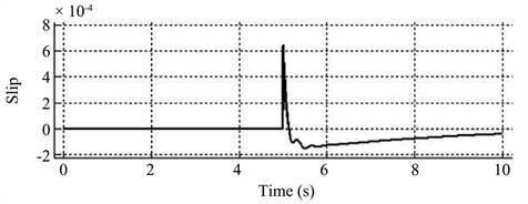
Figure 12. Rotating stator results using proposed control schema.
4. Performance Evaluation for Developed GENSET
4.1. Experimental Setup
This technology tested using developed 500 kw Caterpillar diesel generator and all measurements are extracted from the precise three-phase electric instrument and electronic weighing scale. Table 2 released the genset data. This experiment has been repeated twice. First, the diesel engine runs at 1800 rpm without compensator motor connection (Blocked synchronous motor). In this scenario, the goal is to track DE fuel consumption from the fuel tank by connecting SG into two different electric loads (196 and 307 KW). As for switching DG operating mode from static stator to rotating stator mode, DE stopped completely and restarted to produce 50 Hz frequency. The reason behind this principle is that due to the lack of power converters, this method avoids any harmonic production while switching to the rotating mode. Moreover, CM can work in both 50 Hz and 60 Hz condition. As fast as the DE speed reached its steady state condition, CM starts to rotate at its nominal speed. In terms of the second scenario, CM rotates generator stator using small gearbox. Small gearbox has installed above SG casing and connected to the stator of 500 KW generator. The role of this gearbox is to provide an ideal speed for the synchronous stator. Thus, the stator starts to rotate in order to compensate the necessary speed.
Figure 13 demonstrates that driving belt has used to transfer the rotational torque from CM to the PMSG Stator. The final speed which transfers to the stator has been measured by tachometer at 255 rpm. Therefore, crankshaft speed for diesel engine has reduced to 1545 rpm. Results from these scenarios are shown below when SG connected into two different 196-kW and 307-kW electric loads respectively.
Table 2. Parameters of diesel genset.

Figure 13. Developed GENSET using compound speed.
4.2. Experimental Results
Results below are the PMSG electrical outputs while using rotatory stator. This technology helps DE crankshaft to be more flexible during low electric load. DE speed decreased however, PMSG outputs using rotatory stator are near to the conventional one. Three-phase Fluke multimeter power quality and analyzer device have used to measure PMSG outputs. This technology is tested, and results are indicating in Figure 14 and Figure 15 by connecting PMSG into 196-kW and 307-kW loads respectively. It is important to mention that the compensator speed has kept constant during experiment. No sophisticated gearbox or power converter has used regarding electric outputs treatment.
For the second scenario of this project, CM speed kept constant but resistive load increased. Figure 15 indicates the graph and the parameters of developed PMSG while connecting to the 307-kW load. Frequency and harmonics have shown a very small change by comparing with 196-KW load. AVR system increases the internal excitation of the rotor winding to compensate the load augmentation. Therefore, system voltage kept almost constant as the load increased.


Figure 14. PMSG outputs with proposed structure connecting to 196-kW RL-load.


Figure 15. PMSG results with the proposed structure connecting to 307-kW RL-Load.
5. Experimental Validation
The proposed section is the experimental validation using fixed and Non-static stator mode for PMSG. Modeling and experimental results are compared in Table 3. The goal of this part is to evaluate the impact of the non-static stator on the PMSG out-put. However, it is important to show the optimization of DE consumption using rotatory stator technology. This optimization has achieved while PMSG products, kept at its standard range. Voltage, frequency and other PMSG results are recorded while the prototype ran in its steady state condition. The data collection gathered using power analyzer fluke 435/003, weigh-tronix w1-130 and tachometer A13M2236B.
5.1. Fuel Measurement
The objective of this study brightly shines in this part as the fuel consumption illustrates significant improvement during low loads connection. Figure 16 indicates the fuel optimization of developed GENSET. Fuel rates are considered in liter per hour. By comparing bar charts, the amount of fuel saved for the first load (196-kW) is larger than the second load (307-kW). However, new stator concept has used in both scenarios. During load augmentation, more current absorbed from demand side. Thus, AVR system applied more voltage in rotor winding to meet the energy demand. Whereas, this condition put more stress on DE crankshaft. Inevitably DE governor open fuel hatch more than before to increase the power. Finally, DE crankshaft can rotate the generator rotor at the same speed as it rotates for the first load (mechanical torque increased).
5.2. Fuel Efficiency
This research has proved significant fuel saving by rotating DE at its most efficient speed during low loads connection. Figure 17 approximates the fuel consumption of 500-kW GENSET based on the electrical load at which the generator is connecting to. This experiment was repeated twice for a developed PMSG by connecting 196-kW and 307-kW RL-load into it. By the data released from Figure 16, fuel saving is more significant while developed PMSG, connected to 196-kW-RL-Load. Therefore, fuel saving during low load connection for 500-kW generator is achieved by decreasing mechanical torque on DE crankshaft. It is important to mention that investigation on real fuel saving is always depends on the load impact for an application. This technology could also reduce fuel consumption in another way by replacing smaller diesel engine rather than high capacity DE for the same electric demand. Smaller diesel engine could apply for these kinds of applications due to reduction of mechanical load.
Table 3. Modeling VS prototype validation.
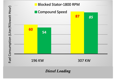
Figure 16. Fuel optimization using rotating stator.

Figure 17. Approximate GENSET consumption (L/hr) comparing with datasheet [31] [32] [33] .
6. Conclusion
Developed PMSG stator using compensator motor is proposed. The principle, simulation and structure of 500-kW GENSET are discussed in detail. This study proves DE fuel optimization, by developing PMSG structure based on rotating mode-stator. Moreover, this development does not have significant negative consequences on the electrical output. This system shows good dynamic durability due to elimination of sophisticated gearbox, high reliability without using power converters, reducing greenhouse gases by optimizing fuel consumption and high steady-state performance.
Conflicts of Interest
The authors declare no conflicts of interest regarding the publication of this paper.
Cite this paper
Mobarra, M., Issa, M., Rezkallah, M. and Ilinca, A. (2019) Performance Optimization of Diesel Generators Using Permanent Magnet Synchronous Generator with Rotating Stator. Energy and Power Engineering, 11, 259-282. https://doi.org/10.4236/epe.2019.117017
References
- 1. Ibrahim, H., et al. (2011) Optimization of Diesel Engine Performances for a Hybrid Wind-Diesel System with Compressed Air Energy Storage. Energy, 36, 3079-3091. https://doi.org/10.1016/j.energy.2011.02.053
- 2. Basbous, T., et al. (2015) Optimal Management of Compressed Air Energy Storage in a Hybrid Wind-Pneumatic-Diesel System for Remote Area’s Power Generation. Energy, 84, 267-278. https://doi.org/10.1016/j.energy.2015.02.114
- 3. Cristóbal Monreal, I. and Dufo-López, R. (2016) Optimisation of Photovoltaic-Diesel-Battery Stand-Alone Systems Minimising System Weight. Energy Conversion and Management, 119, 279-288. https://doi.org/10.1016/j.enconman.2016.04.050
- 4. Karimi, E. and Kazerani, M. (2017) Impact of Renewable Energy Deployment in Canada’s Remote Communities on Diesel Generation Carbon Footprint Reduction. IEEE 30th Canadian Conference on Electrical and Computer Engineering, Windsor, 30 April-3 May 2017, 1-5. https://doi.org/10.1109/CCECE.2017.7946740
- 5. Nejabatkhah, F., et al. (2018) Optimal Design and Operation of a Remote Hybrid Microgrid. CPSS Transactions on Power Electronics and Applications, 3, 3-13. https://doi.org/10.24295/CPSSTPEA.2018.00001
- 6. Saad, Y., et al. (2017) Study of an Optimized Wind-Diesel Hybrid System for Canadian Remote Sites. IEEE Electrical Power and Energy Conference, Saskatoon, 22-25 October 2017, 1-6. https://doi.org/10.1109/EPEC.2017.8286137
- 7. Benhamed, S., et al. (2016) Dynamic Modeling of Diesel Generator Based on Electrical and Mechanical Aspects. IEEE Electrical Power and Energy Conference, Ottawa, 12-14 October 2016, 1-6. https://doi.org/10.1109/EPEC.2016.7771756
- 8. Rezkallah, M., et al. (2016) Control of Small-Scale Wind/Diesel/Battery Hybrid Standalone Power Generation System Based on Fixed Speed Generators for Remote Areas. 42nd Annual Conference of the IEEE Industrial Electronics Society, Florence, 23-26 October 2016, 4060-4065. https://doi.org/10.1109/IECON.2016.7793057
- 9. McGowan, D.J., Morrow, D.J. and Fox, B. (2006) Integrated Governor Control for a Diesel-Generating Set. IEEE Transactions on Energy Conversion, 21, 476-483. https://doi.org/10.1109/TEC.2006.874247
- 10. Ibrahim, H., et al. (2010) Optimizing the Efficiency of a Diesel Engine for a Hybrid Wind-Diesel Experimental Validation. Victoria Univ., Victoria.
- 11. Ibrahim, H., et al. (2010) Study and Design of a Hybrid Wind-Diesel-Compressed Air Energy Storage System for Remote Areas. Applied Energy, 87, 1749-1762. https://doi.org/10.1016/j.apenergy.2009.10.017
- 12. Leuchter, J., et al. (2007) Dynamic Behavior of Mobile Generator Set with Variable Speed and Diesel Engine. IEEE Power Electronics Specialists Conference, Orlando, 17-21 June 2007, 2287-2293. https://doi.org/10.1109/PESC.2007.4342366
- 13. Mohamad Issa, M.M., Ibrahim, H. and Ilinca, A. (2018) Modeling and Optimization of the Energy Production Based on Eo-Synchro Application. Power Engineer, 21, 3-9.
- 14. Deng, J., et al. (2011) Fuel Path Control of a Diesel Engine at the Operating Point of the Low Load and Medium Speed. Chinese Control and Decision Conference, Mianyang, 23-25 May 2011, 747-751. https://doi.org/10.1109/CCDC.2011.5968281
- 15. Ibrahim, H., et al. (2007) Study of a Hybrid Wind-Diesel System with Compressed Air Energy Storage. IEEE Canada Electrical Power Conference, Montreal, 25-26 October 2007, 320-325. https://doi.org/10.1109/EPC.2007.4520350
- 16. Waris, T. and Nayar, C.V. (2008) Variable Speed Constant Frequency Diesel Power Conversion System Using Doubly Fed Induction Generator (DFIG). IEEE Power Electronics Specialists Conference, Rhodes, 15-19 June 2008, 2728-2734. https://doi.org/10.1109/PESC.2008.4592357
- 17. Brace, C., et al. (1999) An Operating Point Optimizer for the Design and Calibration of an Integrated Diesel/Continuously Variable Transmission Powertrain. Proceedings of the Institution of Mechanical Engineers Part D Journal of Automobile Engineering, 213, 215-226. https://doi.org/10.1243/0954407991526810
- 18. Fiset, J. and Tony, D. (2008) United States Patent & Trademark Office—Patent No. US8258641B2: Mechanical Regulation of Electrical Frequency in an Electrical Generation System. 1.
- 19. Fiset, J. (2010) Canadian Intellectual Property Office—Patent No. 2697420: Mechanical Regulation of Electrical Frequency in an Electrical Generation System. W.I.P. Organization, 1.
- 20. Fiset, J. and Tony, D. (2008) Australian Patent—Patent No. 2008291635: Mechanical Regulation of Electrical Frequency in an Electrical Generation System.
- 21. Mohamad Issa, M.M., Fiset, J. and Ilinca, A. (2017) Optimizing the Performance of a 500 KW Diesel Generator: Impact of the Eo-Synchro Concept on Fuel Consumption and Greenhouse Gases. Power Engineer, 21, 22-31.
- 22. Barakat, A., et al. (2010) Analysis of Synchronous Machine Modeling for Simulation and Industrial Applications. Simulation Modelling Practice and Theory, 18, 1382-1396. https://doi.org/10.1016/j.simpat.2010.05.019
- 23. Ibrahim, H., et al. (2012) Wind-Diesel Hybrid System: Energy Storage System Selection Method. 12th International Conference on Energy Storage, Leida, 16-18 May 2012, 10.
- 24. Krause, P.C., et al. (2002) Analysis of Electric Machinery and Drive Systems. Wiley, Hoboken. https://doi.org/10.1109/9780470544167
- 25. Ong, C.-M. (1997) Dynamic Simulations of Electric Machinery: Using MATLAB/SIMULINK.
- 26. Fedák, V., Balogh, T. and Záskalicky, P. (2012) Dynamic Simulation of Electrical Machines and Drive Systems Using MATLAB GUI. In: Katsikis, V., Ed., MATLAB: A Fundamental Tool for Scientific Computing and Engineering Applications, IntechOpen, London, 317-342. https://doi.org/10.5772/48519
- 27. Arrillaga, J.A. and Harker, B. (1983) Computer Modelling of Electrical Power Systems. John Wiley & Sons, Inc., Hoboken.
- 28. Bui, M.X., et al. (2018) A Modified Sensorless Control Scheme for Interior Permanent Magnet Synchronous Motor over Zero to Rated Speed Range Using Current Derivative Measurements. IEEE Transactions on Industrial Electronics, 66, 102-113. https://doi.org/10.1109/TIE.2018.2823663
- 29. Kundur, P., Balu, N.J. and Lauby, M.G. (1994) Power System Stability and Control. Vol. 7, McGraw-Hill, New York.
- 30. Liu, M. and Zhang, X. (2013) Simulation of AC Excitation Field Orientation Control for Hybrid Excitation Synchronous Generator. Proceedings of 2013 2nd International Conference on Measurement, Information and Control, Harbin, 16-18 August 2013, 879-882. https://doi.org/10.1109/MIC.2013.6758101
- 31. Katiraei, F. and Abbey, C. (2007) Diesel Plant Sizing and Performance Analysis of a Remote Wind-Diesel Microgrid. IEEE Power Engineering Society General Meeting, Tampa, 24-28 June 2007, 1-8. https://doi.org/10.1109/PES.2007.386275
- 32. Kiper, D. (2017) CATERPILLAR—Diesel Generator Chart 2017.
- 33. Sheet, G.S.C.D. (2017) Approximate Diesel Fuel Consumption Chart.