Energy and Power Engineering
Vol.5 No.6(2013), Article ID:35707,10 pages DOI:10.4236/epe.2013.56041
Studying the Role Played by Evaporative Cooler on the Performance of GE Gas Turbine Existed in Shuaiba North Electric Generator Power Plant
Water Resources Dept., High Institute of Energy, Public Authority of Applied Education & Training, Kuwait
Email: alaa_saker@yahoo.com
Copyright © 2013 O. R. AL-Hamdan, A. A. Saker. This is an open access article distributed under the Creative Commons Attribution License, which permits unrestricted use, distribution, and reproduction in any medium, provided the original work is properly cited.
Received May 31, 2013; revised June 31, 2013; accepted July 7, 2013
Keywords: Gas Turbine; Shaft Speed; Power Output; The Evaporative Cooling Technique
ABSTRACT
It’s well known that the performance of a gas turbine (efficiency, heat rate and power generated) is largely dependent on mass flow rate of air, inlet air temperature and turbine inlet temperature (TIT). As turbine inlet temperature is dependent on quantity of burned fuel so that this factor is dropped out from this paper. It’s also known that gas turbines are constant volume machines i.e. at a given shaft speed they always move the same volume of air, but the power output of a turbine depends on the flow of mass through it. This is precisely the reason why on hot days, when air is less dense, power output falls off. A rise of one degree Centigrade temperature of inlet air decreases the power output by 1% and at the same time heat rate of the turbine also goes up. This is a matter of great concern to power producers. Many techniques have been developed to cool the inlet air to gas turbine. Some of these techniques to decrease the inlet air temperature are discussed here. The evaporative cooling technique is taken as a case study in this paper. A comparative studying is carried out between a unit using this technique and the same unit when the evaporative cooler is idle. The results advert to an increase in power output by 11.07% and a decrease in heat rate by approximately 4% when inlet air temperature drops from 50˚C to 26˚C.
1. Introduction
Electric generator power plants play a great role in developing countries. The modern techniques in generating electricity from fossil fuel are by using the so-called combined units through combined cycle. The combined cycle in Shuaiba North power plant consists of three unit gas turbine and one unit steam turbine. The performance characteristics of these units are the most important judging element. The main factors affecting unit performance characteristics are the inlet air temperature to the compressors of the gas turbine units. The research will focus on the system of inlet air cooling to a compressor of GE Gas turbine unit, 250 MW capacities as a case study.
2. Literature Survey
An inlet cooling system is a beneficial option for applications where significant operations occur during times of warmer temperatures combined with low relative humidity. Cooler air is denser, resulting in a higher mass flow rate to the compressor. This results in an increase in turbine output and efficiency [1].
Evaporation of water is one of the simplest and oldest methods of cooling air. Even with the sophisticated technology available today, including mechanical chillers, absorption chillers and thermal energy storage systems, evaporative cooling remains a most cost-efficient method for temperature control of the gas turbine inlet air supply [2].
Evaporative cooling can be achieved by many methods. In practical two forms are typically used. Media type evaporative cooling and spray type evaporative cooling.
The most famous for media type evaporative coolers consist of re-circulated water sprayed over an extended surface media mounted downstream from the inlet air filters. As inlet air passes through the water soaked evaporative cooler media, evaporation occurs performing a double function:
1) Energy in the form of heat is removed from the air and in the same time that energy is used to evaporate water in the media; and 2) Water vapor content of the air increases due to evaporated water approaching saturation along constant wet bulb lines.
These two processes increase the density of the air, which in turn increases the mass flow and output of the gas turbine.
3. Cycle Thermodynamic Consideration
3.1. Gas Turbine Cycle Thermodynamics
The compression process consumes as much as 66% of the total work produced by the gas turbine and therefore any means of reducing the work of compression will enhance the power output of the gas turbine. The compressor work per unit mass of air is given by:
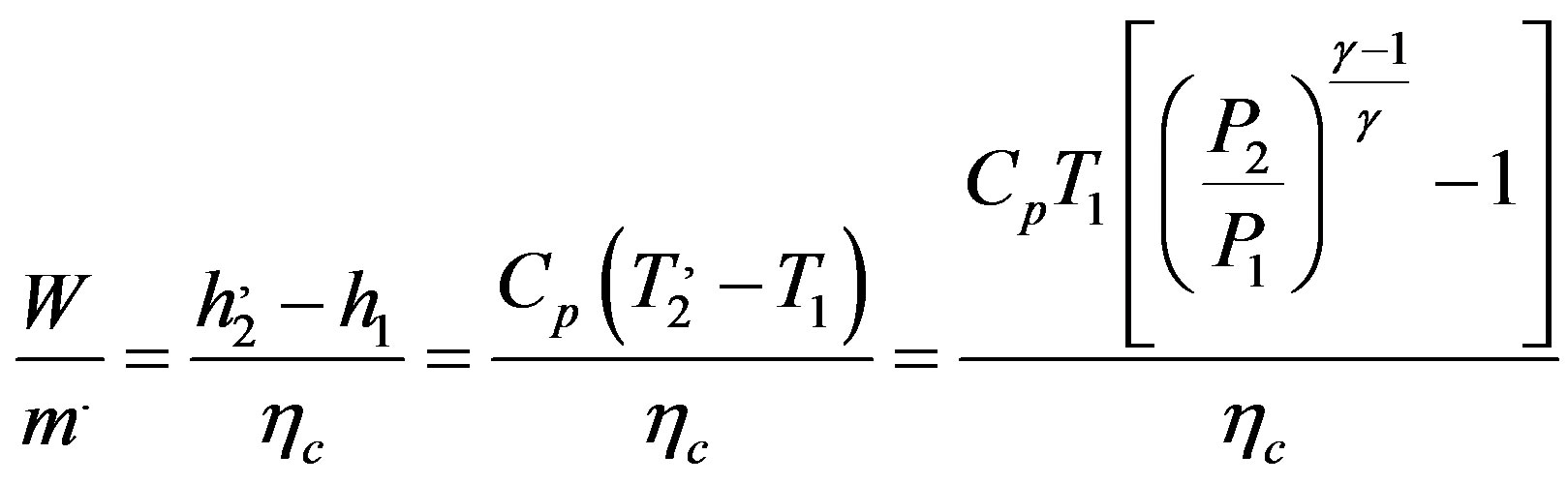 (1)
(1)
In examining this equation, it can be seen that increasing T1 would increase the compression work.
Assuming no pressure losses, and equal specific heats in the cycle gas turbine, thermal efficiency can be reduced to the equation below (Sorenson, 1950) [3].
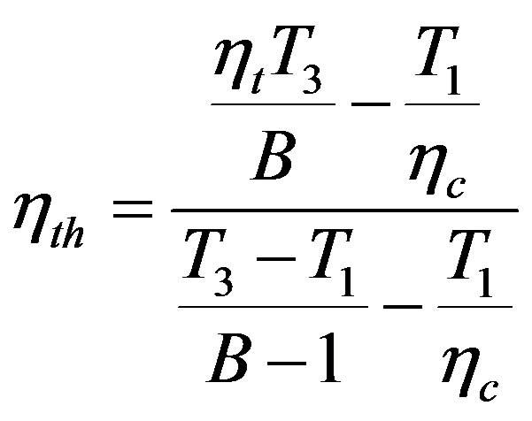 (2)
(2)
where:
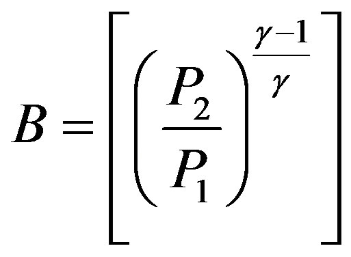
 = Compressor efficiency, ηt = Turbine efficiency, T3 = Turbine inlet temp.,
 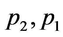 = Cycle pressure limits.
Examination of this equation shows that the cycle efficiency decreases with an increase in compression inlet temperature. When the inlet temperature goes up the compressor discharge pressure and temperature drops and more fuel is required to attain the same turbine inlet temperature (TIT).
An increase in ambient temperature T1 causes the numerator, representing net power output to decrease at a faster rate than the denominator, representing the heat delivered. So the cycle efficiency decreases with increasing inlet compressor temperature.
Figure 1 shows a T-S diagram on a hot day the drop in pressure ratio that occurs on the hot day can be seen on this diagram. The cycle peak temperature is still limited as before and so the expansion ratio also drops meaning that less work is extracted from the turbine. As the compressor work increases and the turbine work decreases, the output power drops [3].
Further, as the ambient temperature increases, the pressure ratio of the compressor decreases and more fuel has to be added to attain the same turbine inlet temperature (TIT) this further decreases the output of the gas turbine unit and the cycle efficiency drops [3].
3.2. Effect of Inlet Air Temp. on GE Gas Turbine Performance Characteristics
GE offers a table explains the effect of inlet air temperature on the power output and heat rate of many models of gas turbine. Table 1 provides a complete listing of the available outputs and heat rates of the GE heavy-duty gas turbines [4].
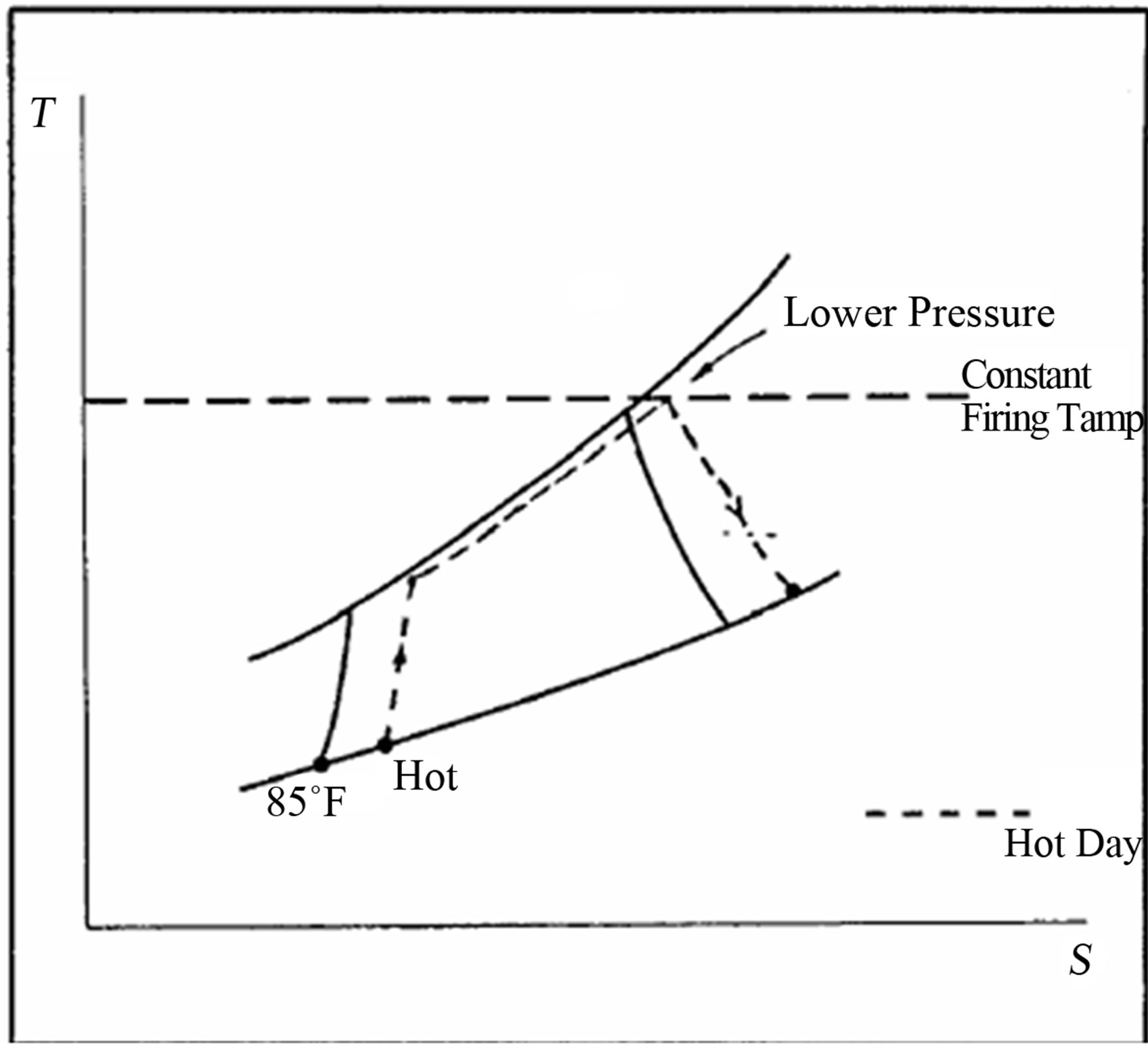
Figure 1. T-S Diagram of Simple Brayton Cycle on Hot Day.
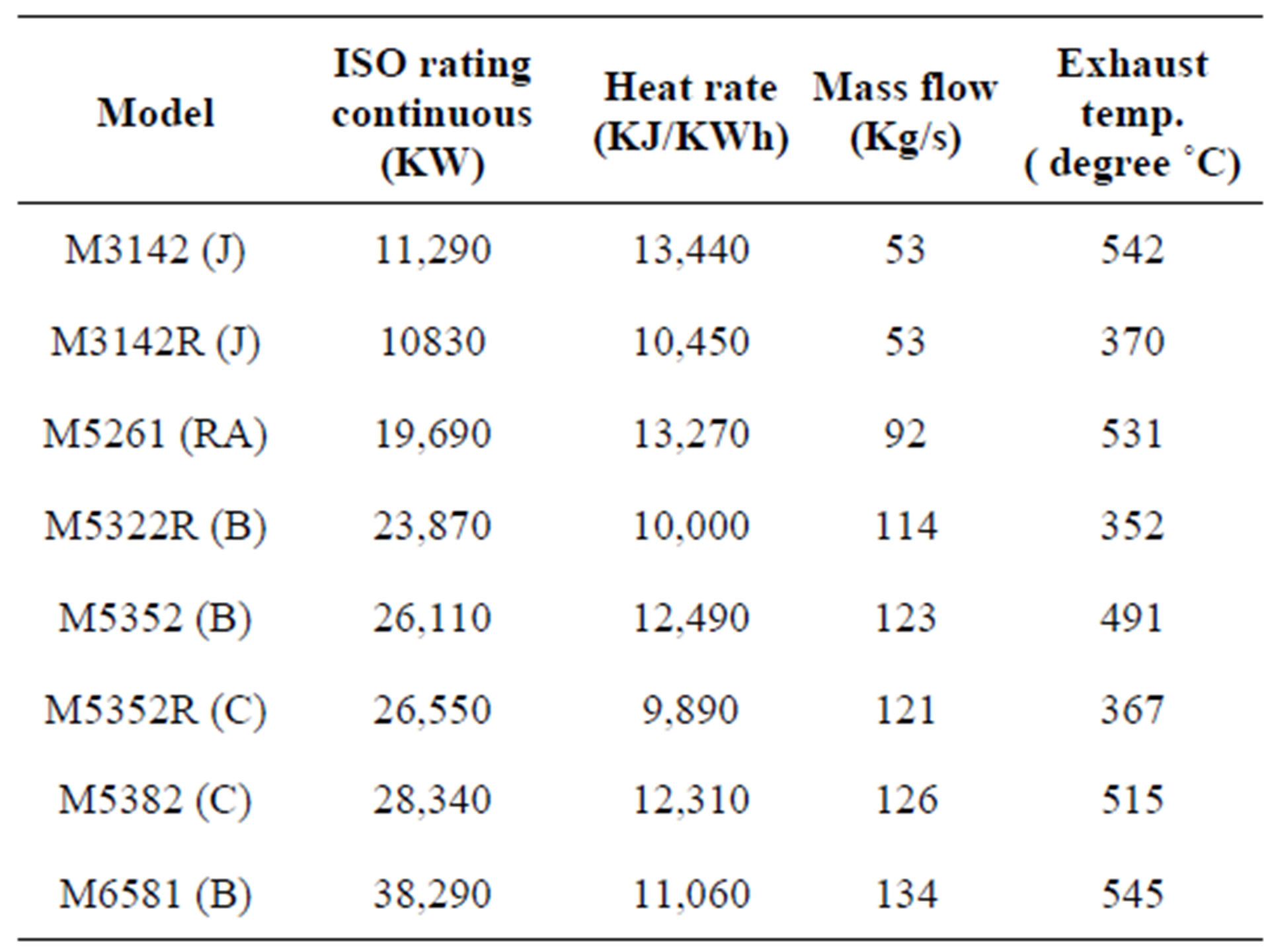
Table 1. GE gas turbine performance characteristics— Mechanical drive gas turbine ratings.
3.3. Factors Affecting Performance of Gas Turbine
The performance of Gas Turbine viz. the power output and the heat rate (measure of efficiency, i.e. the amount of energy consumed per kWh of electricity produced) depends on the following major parameters [5].
1) Site altitude i.e. atmospheric pressure.
2) Inlet pressure drops in the filters and intake system.
3) Outlet pressure drops in the HRSG (Heat Recovery Steam Generator).
4) Site design temperature.
5) Site design relative humidity corresponding to the site design temperature.
3.4. Impact of Higher Inlet Air Temperature on Gas Turbine Performance
A gas turbine is a constant volume machine i.e. the volume of air compressed is fixed, irrespective of ambient temperature. Hence, as the temperature of air raises the density of air decreases and the mass flow rate of compressed air gets reduced. The power output of the gas turbine is proportional to the mass flow rate of air. Thus as the ambient temperature increases, the power output decreases. Further, the efficiency of the gas turbine also falls, as more power is required to compress warmer air, from the above paragraph (factors affecting performance of gas turbine). For a given site and the configuration, the first three parameters are constant and cannot be changed. However, it is possible to alter the other two parameters and obtain a higher output and improved efficiency by cooling the air before it is admitted in the gas turbine compressor section. Impact of higher ambient air temperature is very well spelled in a given Figure 2 [5], and Table 2 [6].
4. Methods Currently Adopted by Industry
Industry has implemented various techniques to reduce ambient temp. They are as follows [5]:
1) Vapor Compression:
Various refrigerant type air-chilling systems are available in the market. The biggest advantage of this is that one can reduce temp of inlet air up to 15˚C. The biggest disadvantage in this system is higher power consumption to cool inlet air and pressure drop in the air,
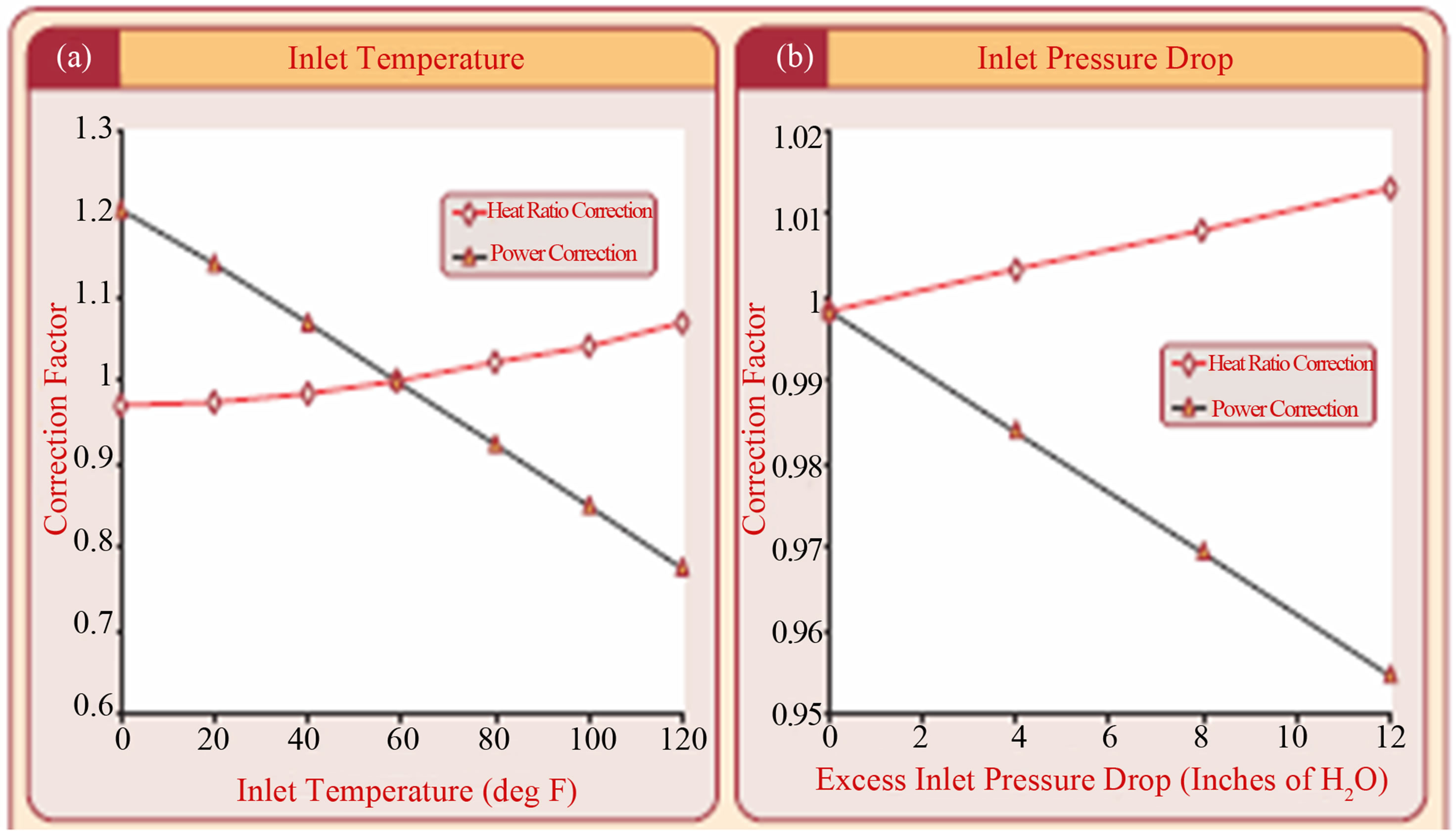
Figure 2. Changes in Power Output and Heat Rate for a 40 MW Gas Turbine Output to: (a) Inlet Air Temperature. (b) Inlet Pressure Drop.
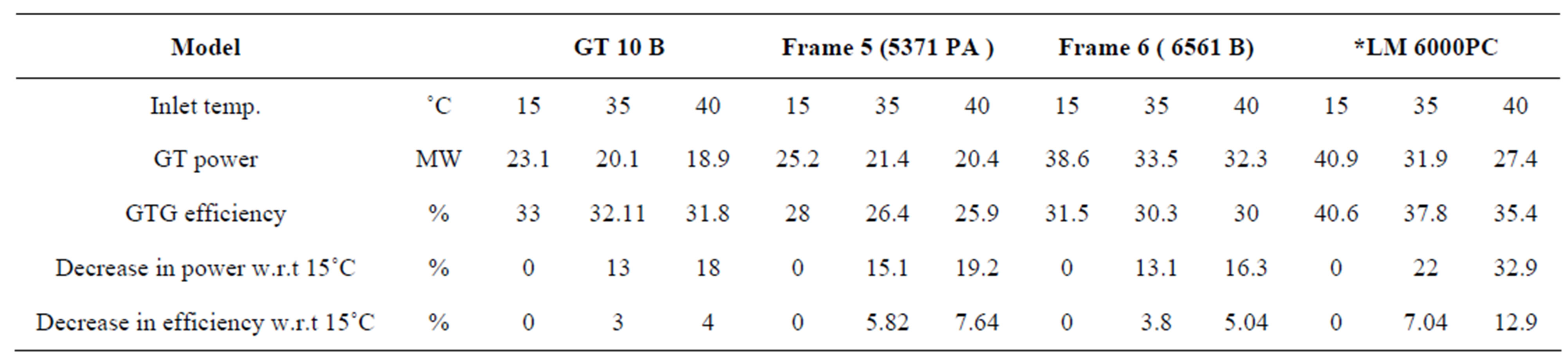
Table 2. Performance of various gas turbine models with respect to inlet air temperature.
thus adversely affecting the performance of compressor.
2) Vapor Absorption Chillers:
Steam is used to give the chilling effect and one can achieve 15˚C inlet air temperature.
This system consumes steam which reduces output of the steam turbine .It also reduces the inlet air pressure which adversely affects the performance of compressor.
3) High Pressure Fog system:
It’s one of the recent technologies employed for inlet air cooling. It's similar to evaporative cooling, but instead of using water as an evaporative medium, the water is atomized into billions of supper small droplets thereby creating a large evaporative surface area. With fog overcooling arrangement, one can generate more power. The biggest disadvantages of this technique are high cost of high pressure nozzles, high vibration, prices of high pressure pumps and the ability of erosion in compressor blades.
4) Evaporative Cooler:
Evaporative cooling works on the principle of reduceing the temperature of an air stream through water evaporation. The process of converting water from liquid to a vapor state requires energy. This energy is drawn from the air stream, the result being cooler and more humid air. The effectiveness of an evaporative cooling system depends on the surface area of the water exposed to the air stream and the residence time. Performance of the system is restricted by the amount of moisture present in the air. It works well in low humidity area.
5. The Present Work (Case Study)
For better choice between the cooling methods it’s necessary to take into consideration the following factors:
1) Capital cost.
2) Maximum achievable cooling range.
3) Auxiliary power/steam consumption.
4) Reliability of the system.
5.1. Evaporative Cooler in Shuaiba North Gas Turbine Power Plant
The system existed in Shuaiba North gas turbine power plant for decreasing the inlet air temperature to the compressor consists of two centrifugal water pumps with capacity 20 m3/hr and 120 m head. The two pumps are parallel arrangement. Figure 3 shows the line diagram of the system arrangement.
The evaporative cooling system arrangement is also shown in Figure 4 [7].
5.2. Thermodynamic Relationships of Evaporative Cooler System
The function of the evaporative cooler is to increase turbine output by lowering the inlet dry bulb temperature and increasing the air density through the evaporation of water into the inlet airflow. Re-circulated water introduced over the top of the evaporative cooler media drains through and wets the media. Filtered ambient air comes into contact with the wetted media where the air is
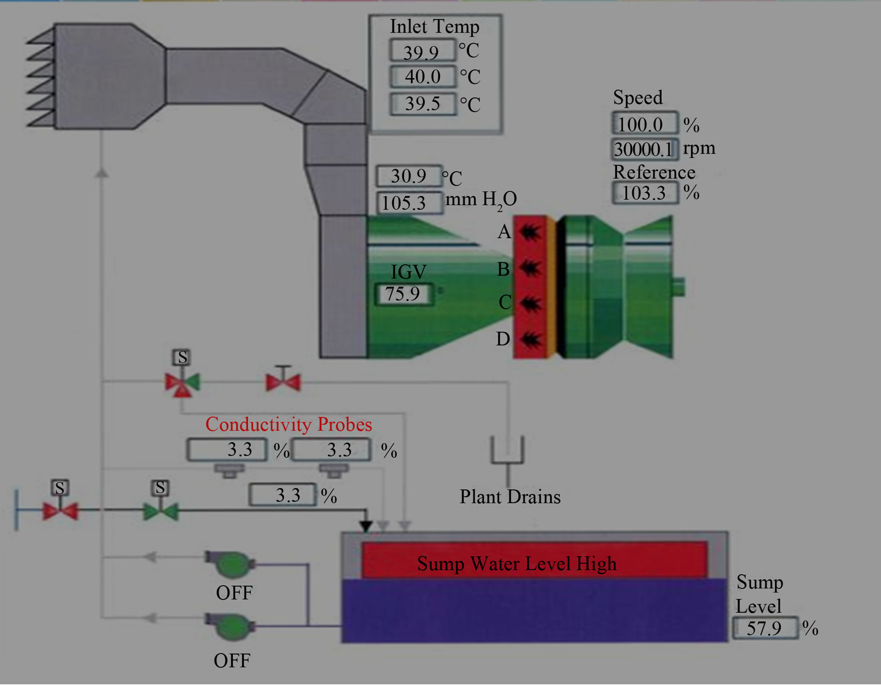
Figure 3. Schematic Diagram of Evaporative Cooling Components.
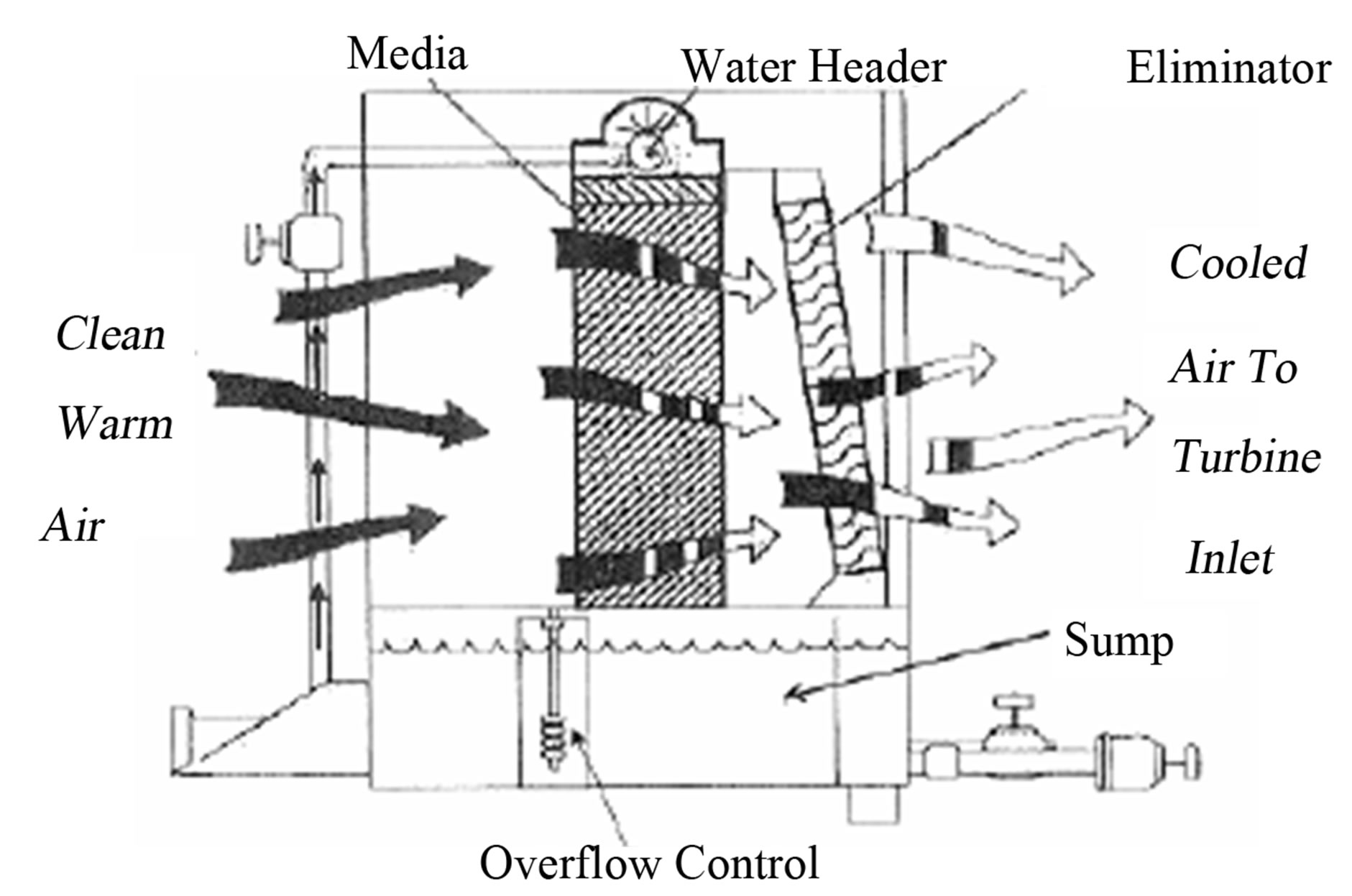
Figure 4. Schematic Diagram of an Evaporative Cooling.
cooled by the heat of evaporation of water. Gas turbine mass flow rate increases due to the lower air temperature and increased water content. Higher mass flow results in increased power output from the gas turbine. When discussing media type evaporative coolers, a couple of key parameters are essential to the proper operation and maintenance of evaporative coolers. These evaporative cooler parameters are: Saturation Efficiency, Evaporation Rate, Blow down Rate, Makeup Water Rate, Water Carryover, and Water Bypass
5.2.1. Saturation Efficiency (Effectiveness)
The performance of an evaporative cooler is based on the ratio of the number of degrees it can cool the air compared to the wet bulb temperature depression. As air passes through an evaporative cooler, the dry bulb temperature is lowered, but the wet bulb temperature remains approximately the same.
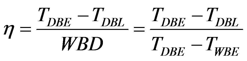
The dry bulb temperature will then approach the wet bulb temperature as the air is cooled and the relative humidity will rise (due to moisture added to the airflow through evaporation). The entering wet bulb temperature is a function of the entering conditions of the airflow (air dry bulb temperature, ambient pressure or altitude with respect to sea water level, and relative humidity). Since an evaporative cooler operates along constant wet bulb temperature lines, the entering wet bulb temperature determines the maximum amount of cooling that can be achieved. We can define the saturation efficiency of an evaporative cooler as the ratio between the actual amounts of cooling achieved (difference between entering and exiting airflow temperatures) and the maximum allowable cooling per the entering conditions (Wet Bulb Depression). The effectiveness of an evaporative cooler may be calculated using the following formula and Figure 5 [7].
 (3)
(3)
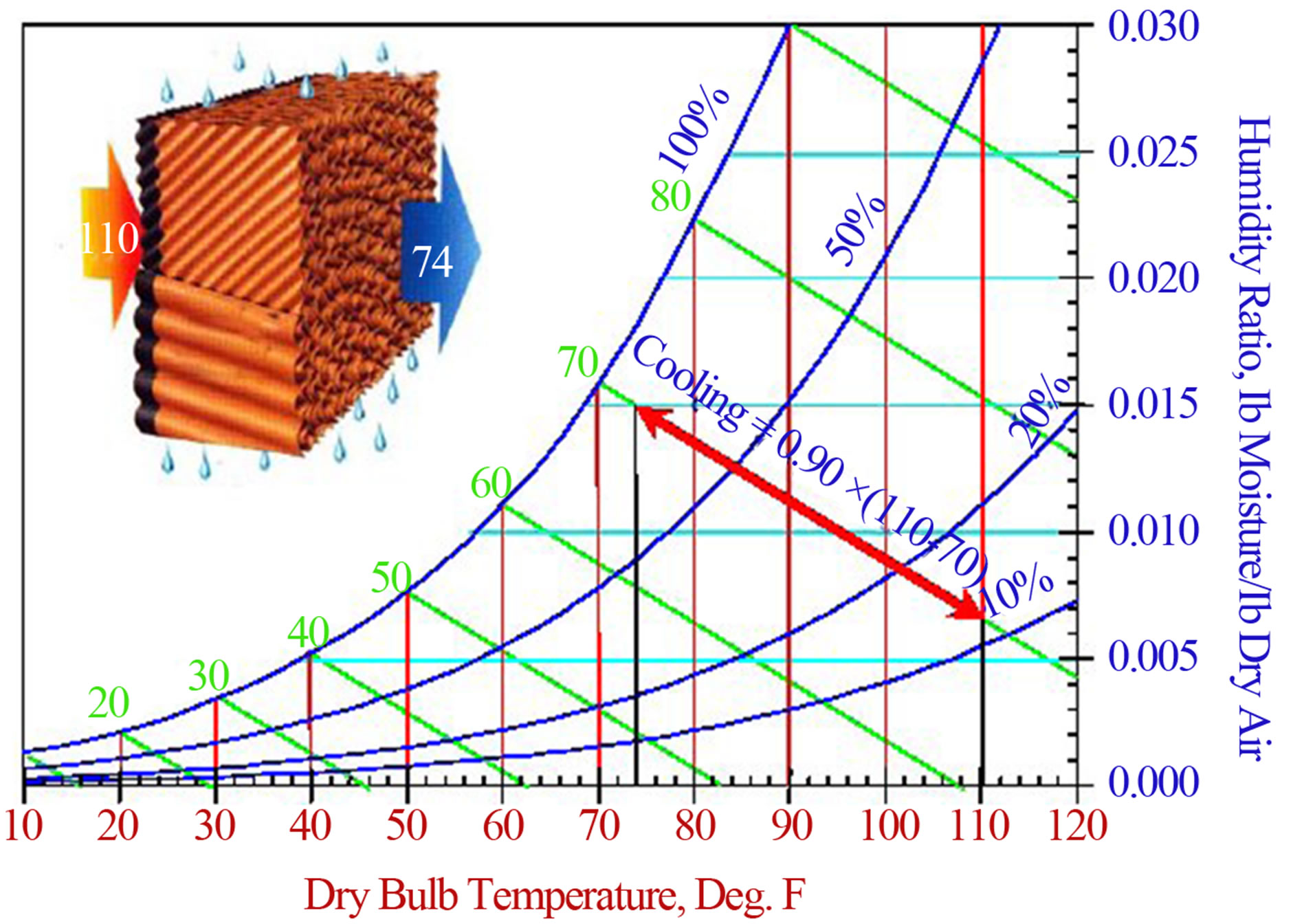
Figure 5. Evaporative Cooler Process on Psychometric Chart.
where:
η = Efficiency in percent.
TDBE = Entering Dry Bulb Temp TWBE = Entering Wet Bulb Temp TDBL = Leaving Dry Bulb Temp WBD = Wet Bulb Depression, or =TDBE − TWBE
1) Dry Bulb Temperature The temperature as measured by a standard thermometer.
2) Wet Bulb Temperature If the air is at a temperature above its dew point, evaporation of water will occur in the wick causing cooling and the reading of a temperature below the dry bulb temperature, the wet bulb and dry bulb temperatures are equal at 100% humidity.
The Wet Bulb Depression is the difference between the ambient dry bulb and the wet bulb temperature. The Wet Bulb Depression is the maximum amount of cooling achievable with a 100% efficient evaporative cooler system.
3) Humidity Humidity, which is expressed by the water vapor pressure in air, is controlled by the ambient temperature. Relative Humidity is the ratio of the vapor pressure of water in air compared the saturated water vapor pressure at the same temperature. Dew Point Temperature of the air is the temperature at which condensation of liquid water may occur.
4) Ambient Pressure The temperature and barometric pressure of atmospheric air vary considerably with altitude as well as with local geographic and weather conditions. The standard atmosphere gives a standard of reference for estimating properties of air at various altitudes. At sea level, the standard barometric pressure is 14.696 Ib/in2 [29.921 in. Hg] and the standard temperature is 59˚F [15˚C]. The temperature is assumed to decrease linearly with increasing altitude while the specific volume increases. The lower atmosphere is assumed to consist of dry air that behaves as a perfect gas.
5.2.2. Evaporation Rate
The evaporation rate is the amount of water that is added to the gas turbine airflow as a result of the energy transfer between airflow and water, and the subsequent evaporation of water into the air. The amount of water evaporated into the air or evaporation rate will depend on the entering ambient air conditions. Factors such as dry bulb temperature, relative humidity, and air ambient pressure determine the maximum amount of water that may be evaporated before air becomes “saturated” with water.
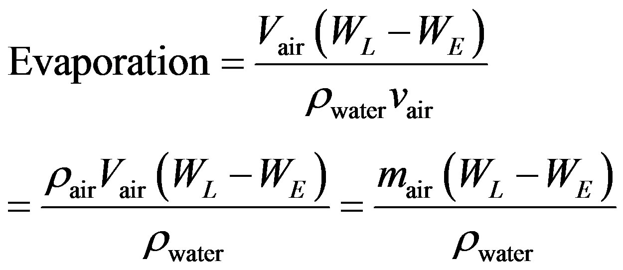
The amount of water evaporated in gallons per minute as the air passes through the cooler can be calculated using the psychometric chart using the following formula:
 (4)
(4)
where:
Vair = Actual volumetric flow rate of air (cubic feet of air per minute or CFM)
ρwater = Density of water (lb water/gal) at TWBE
ρair = Density of air (lb air/ft3) at entering airflow conditions WE = Moisture content of entering air (lbs. water/lb. dry air)
WL = Moisture content of leaving air (lbs. of water/lb. dry air)
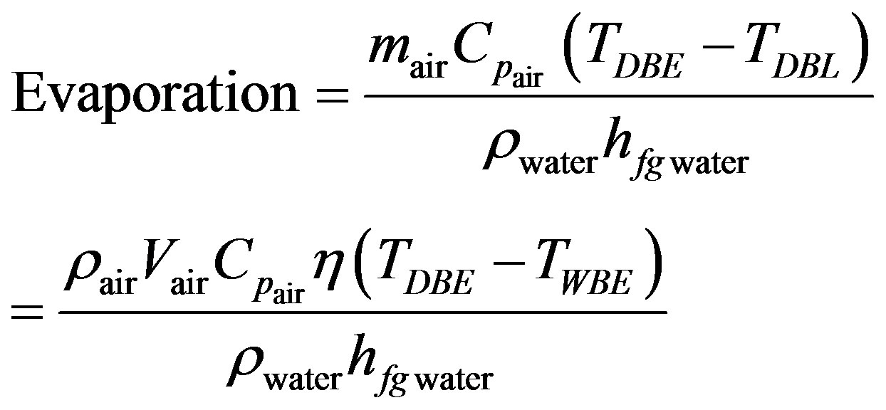
mair = Mass airflow rate (lb. dry air/min) at entering conditions Vair = Specific volume of air (ft3/lb. dry air) at entering conditions Similarly, since the evaporation rate is a function of the temperature of the ambient air and airflow, the amount of water evaporated may be obtained from the energy balance equation between air entering and leaving the evaporative cooler media:
 (5)
(5)
where:
TDBL = Dry bulb temperature at leaving from evaporative cooler.
TDBE = Dry bulb temperature at entrance to evaporative cooler.
TWBE = Wet bulb temperature at entrance to evaporative cooler.
CPair = Specific heat of air at TDBE (Btu/lb. ˚F)
hfgwater = Heat of evaporation of water (Btu/lb water) at TWBE
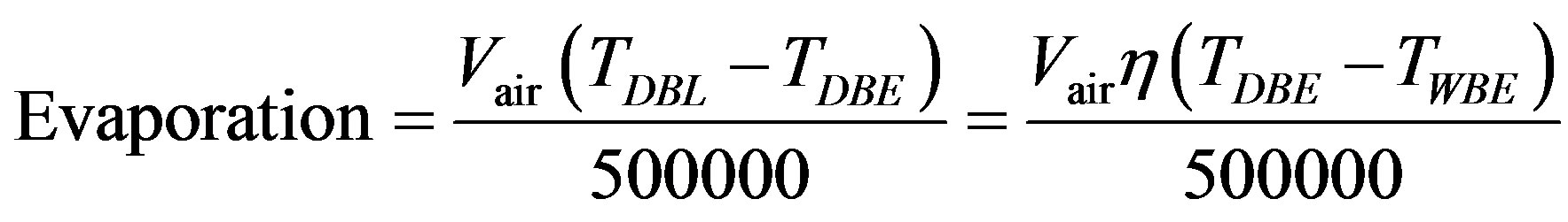
For practical purposes, the following version of the energy balance equation is used:
 (6)
(6)
5.2.3. Blow down (Bleed-Off) Rate
Water always contains a certain amount of dissolved minerals. The process of evaporative cooling removes pure water as vapor from the re-circulating flow and leaves behind the solids that had been dissolved in the water when it was added as makeup. Accordingly, enough water must be blown down from the re-circulating flow to control the level of these solids and to avoid build-up of insoluble minerals on the pad surface (commonly referred to as “scaling”), which results in an increase in pressure drop, and a loss of evaporation area and efficiency.
Blow down is the flow of water that must be continuously removed from the cooler in order to maintain the chemistry of the re-circulating water at the design value. It is a function of evaporation rate and the cycles of concentration that can be achieved with a given water quality in the system.
 (7)
(7)
The chemistry of the sump is established by determining the maximum cycles of concentration that the makeup water can go through. By definition, the number of cycles of concentration is equal to the number of times that incoming (makeup) water may be re-circulated before it is removed (bled) from the system. Two methods are commonly used for controlling blow down and maintaining the desired chemistry in the sump of the evaporative cooler: Constant flow and Conductivity control blow down.
5.2.4. Makeup Water Rate
Makeup water is the water added to the sump of the evaporative cooler to replace the water lost by evaporation into the airflow and the water removed from the sump through blow down or bleed-off as required.
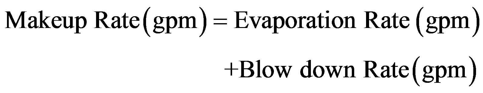 (8)
(8)
When conductivity control is used to control blow down, the makeup water required while blow down is on will be higher than the average identified by the makeup rate formula. When the blow down is off (Blow down rate = 0 gpm), the required make up rate will be equal to the current evaporation rate.
A high makeup water rate is typically required during startup of the evaporative cooler system in order to ensure enough water is available out of the sump (recirculation) tank during initial wetting of media.
5.3. Role Played by Evaporative Cooler on Power Output and, Heat Rate of Shuaiba North Gas Turbine Power Plant
From Table 3 which show the properties of air at entering and leaving from evaporative cooler, When using the evaporative cooling techniques the power output = 224.9 MW and heat rate = 9882.2 kj/kw hr - when the ambient conditions are: dry bulb inlet temperature TDB = 42.48 C, inlet pressure = 0.99 bar and relative humidity = 12%, the leaving conditions from the evaporative cooling are as follows:
Exit dry bulb temperature TDBL = 22.43 CExit pressure= 0.98 bar, and the relative humidity = 85.11%.
At entrance to evaporative cooler from Figure 5.
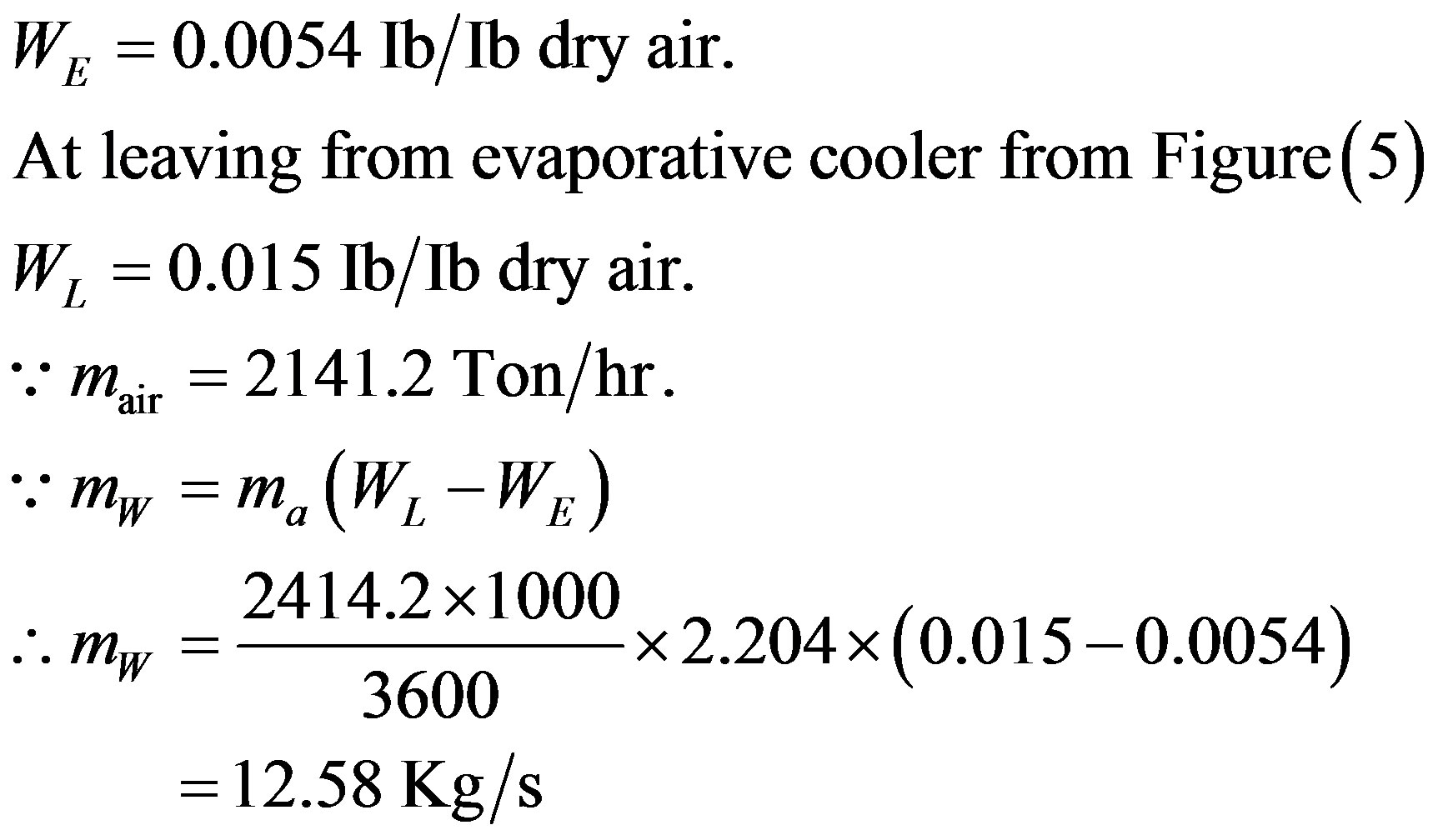 (9)
(9)
6. Calculation of Evaporative Cooling Efficiency
Using the data in Table 4 which shows the humidity ratio at entering and leaving from evaporative cooler:

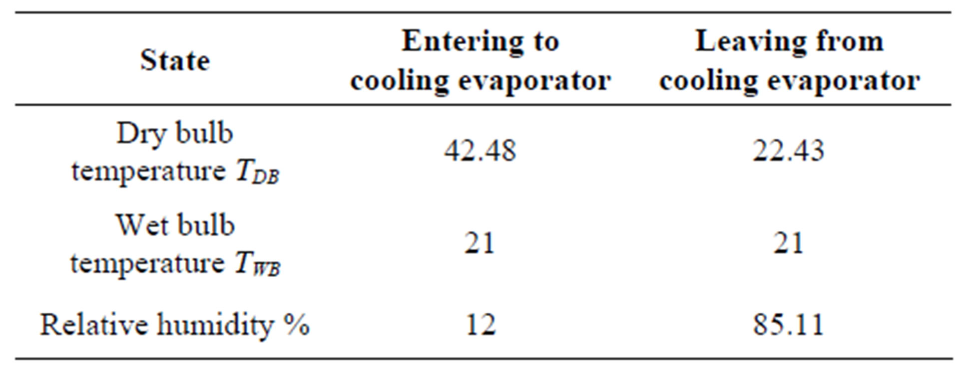
Table 3. Properties of air at entering and leaving from evaporative cooler.
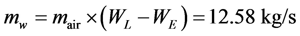
6.1. Humidity
Amount of air entered when power output = 224.9 MW, mair = 2141.2 Ton/hr.
Amount of water used when power output = 224.9 Mw is
6.2. Power Saved at Various Inlet Temperatures
Table 5 determines the amount of power saved as a result of using evaporative cooler in services in Shuaiba North gas turbine power plant at different inlet air temperature.
7. Differences in Heat Rate When Using the Evaporative Cooling Techniques
Table 6 below shows the quantity of gas oil and natural gas fuels consumed in producing 225 Mw/unit from Shuaiba North gas turbine power plant when evaporative cooler in service and when it was out of services. It’s clear that the quantity of fuel consumed increases when evaporative cooler is out of services, especially during hot weathers.
8. Money Saved When Using the Evaporative Cooler Techniques
The unit price of gas oil and natural gas fuels in 23 January 23, 2012 are as follows [8].
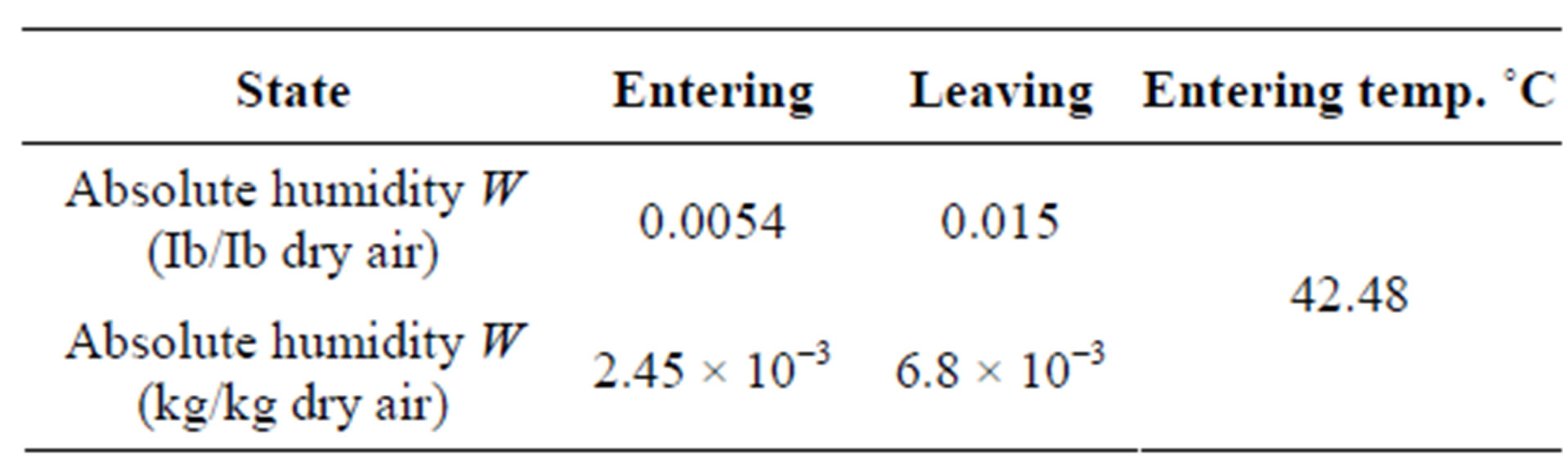
Table 4. Humidity Ratio at Entering and Leaving from Evaporative Cooler.
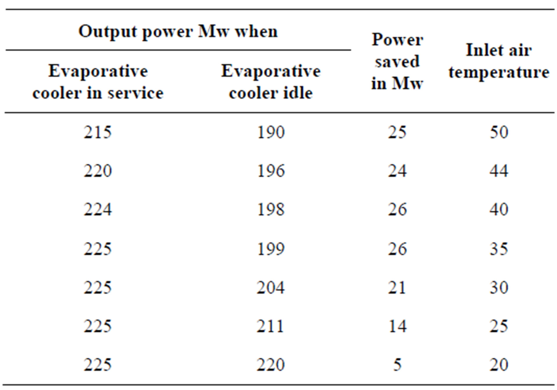
Table 5. Output power saved as a result of using an evaporative cooler.
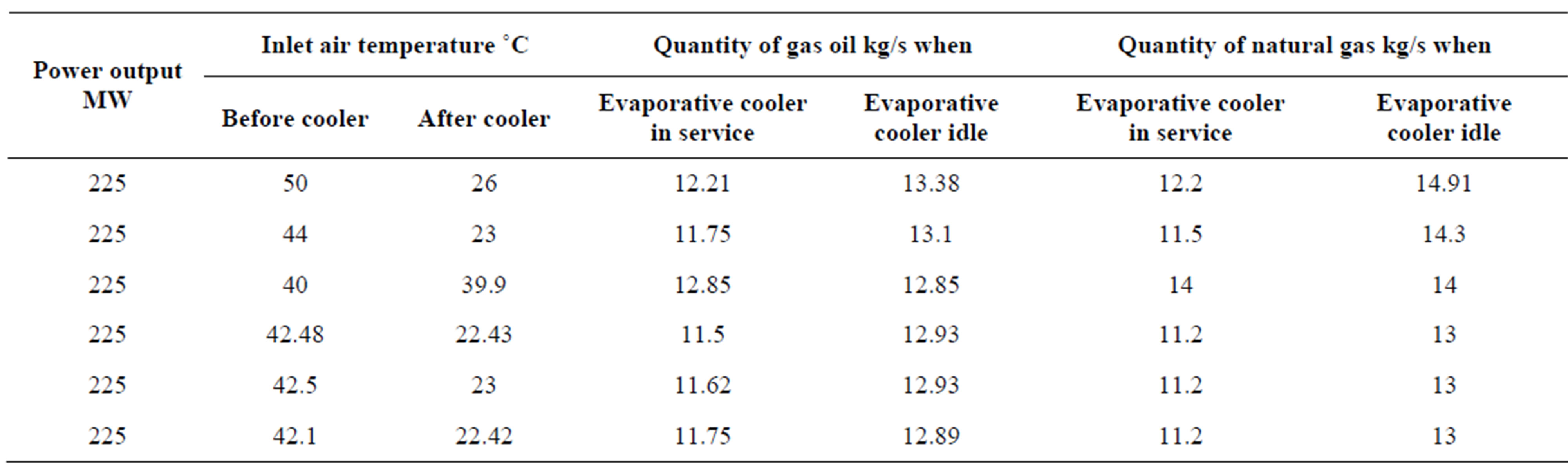
Table 6. Quantity of fuel consumed at different inlet air temperature.
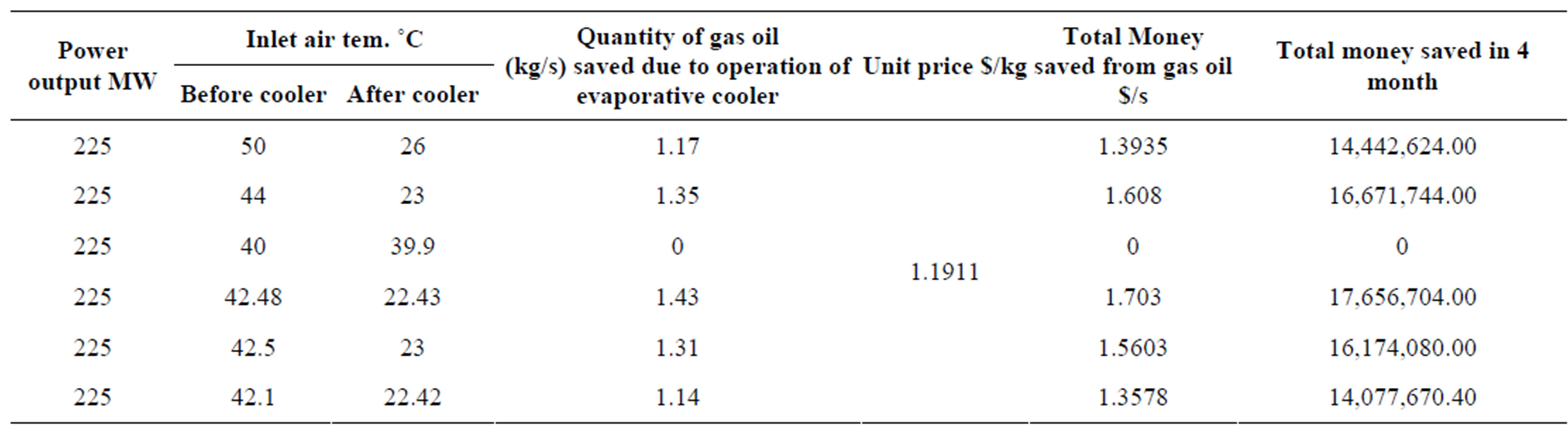
Table 7. Money saved due to using evaporative cooler in Shuaiba North gas turbine power plant.
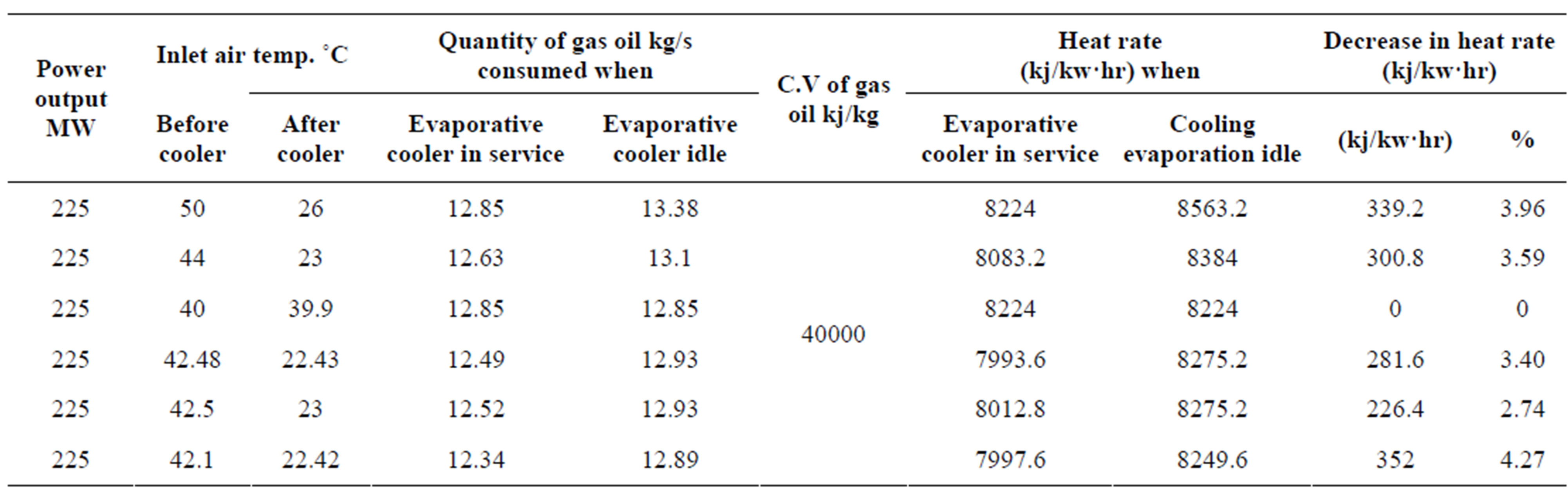
Table 8. Decrease in heat rate in (kj/kw·hr) When Evaporative Cooling in Service.
Diesel (Gas oil) $3.945 per Gallon (US).
Natural Gas $1.0324 per Thermo.
When using evaporative cooler during hot weathers a lot of money can be saved as a result of decreasing the amount of fuel burned. Table 7 determine a sample of money saved when power output = 225 MW. When inlet air temperature ranging from 40˚C - 50˚C.
Heat Rate
Another important factor in determining the role played of evaporative cooler in Shuaiba North gas turbine power plant is the heat rate in (Kj/Kw·hr). The decrease of heat rate means the more efficient the gas turbine unit.
Table 8 determines the heat rate for Shuaiba North gas turbine power plant when power output 225 Mw. and inlet air temperature range 40˚C - 50˚C.
9. Discussions
It’s clear from Figure 6 that as the inlet air temperature decreases, the output power increases, which is due to increase in inlet air density which retails increases of inlet mass flow rate which leads to increases of gas turbine power output.
From Figure 7 there is a considerable amount of money saved as a result of using evaporative cooling techniques because less fuel consumed at constant turbine inlet temperature (TIT = constant ).
From Figure 8 and Figure 9 as the inlet air temperature decreases, a significant decreases in heat rate is also detected.
From Figure 10 it can be noticed that there is a significant needs to use evaporative cooler especially at high temperature and low humidity.
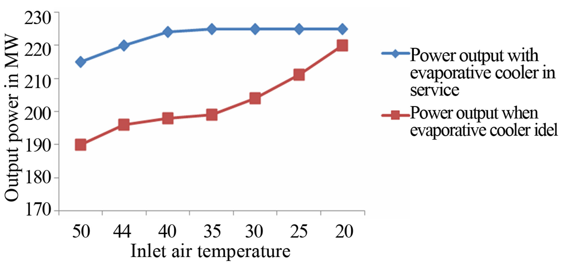
Figure 6. Effect of Inlet Air Tem. On the Power Output from Shuaiba North Gas Turbine.
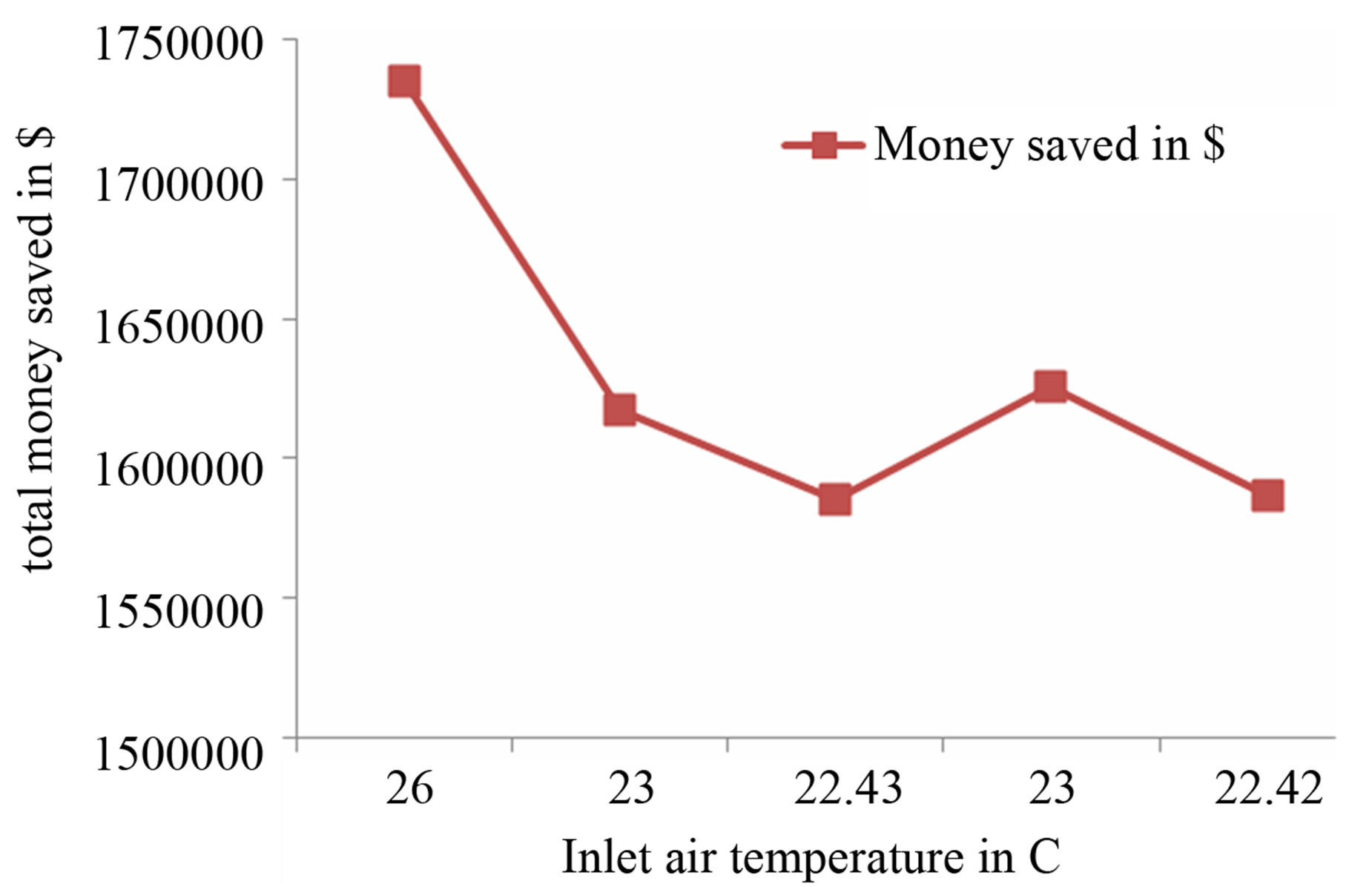
Figure 7. Money Saved When Using Evaporative Cooler in Shuaiba North Gas Turbine in $.
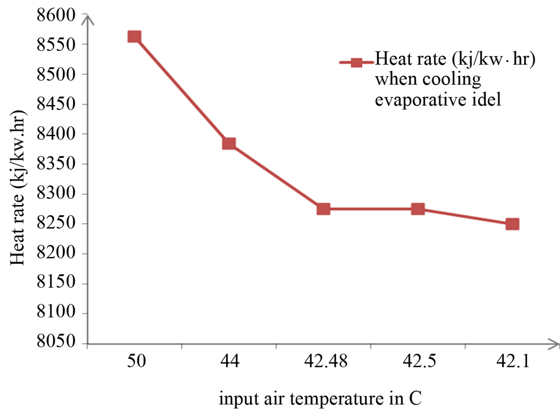
Figure 8. Effect of Input Air Tem. On Heat Rate (Kj/Kw·hr) When Cooling Evaporative Idle.
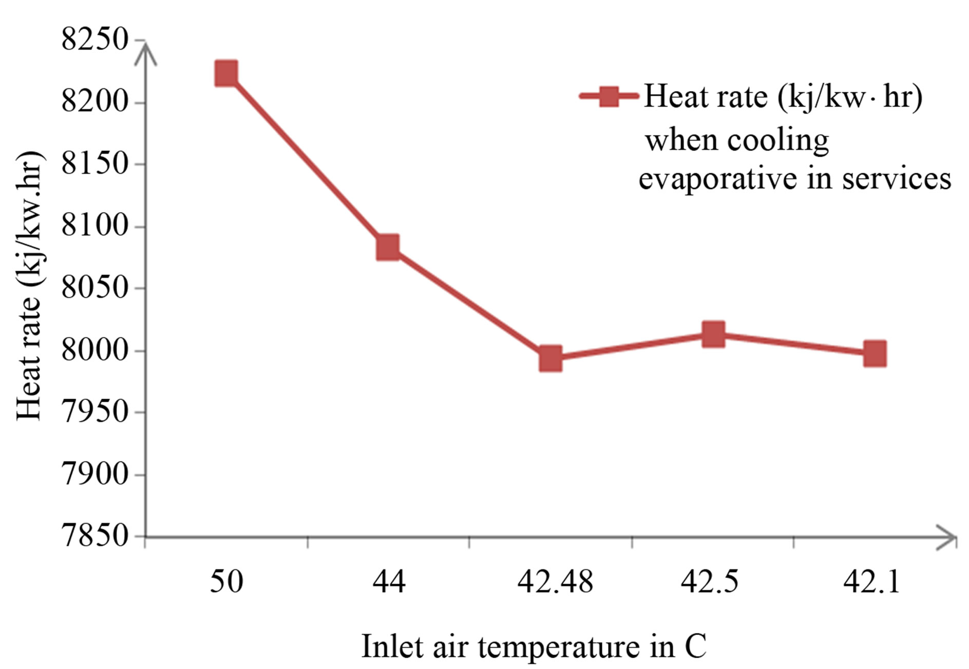
Figure 9. Effect of Input Air Tem. On Heat Rate (Kj/Kw·hr) When Cooling Evaporative in Service.
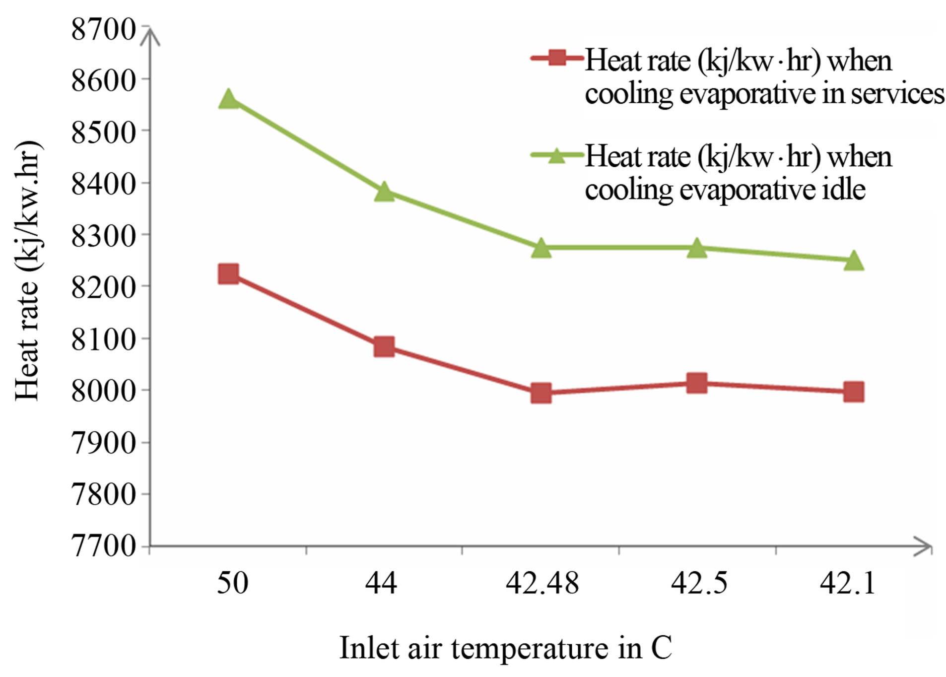
Figure 10. Comparison between Heat Rate in (Kj/Kw·hr) Versus Inlet Air Temp.
10. Suggestions and Recommendations
For more power output and lower heat rate from a gas turbine, a combination of two methods of air cooling techniques can be used but, this techniques needs more analysis in future works.
REFERENCES
- M. Chaker, C. B. M. Homji and Thomas Mee III, “Inlet Fogging of Gas Turbine Engines-Part A: Fog Droplet, Thermodynamics, Heat Transfere and Practical Considerations,” Proceedings of ASME Turbo Expo 2002, 3-6 June 2002, Amsterdam.
- M. Chaker, C. B. M. Homji and Thomas Mee III, “Inlet Fogging of Gas Turbine Engines,” Proceedings of ASME Turbo Expo 2001, 4-7 June 2001, New Orleans.
- C. B. M. Homji and Thomas Mee III, “Inlet Fogging of Gas Turbine Engines—Part B: Practical Considerations, Control, and O&M Aspects,” Proceedings of ASME Turbo Expo 2000, 8-11 May 2000, Munich.
- F. J. Brooks, “GE Gas Turbine Performance Characteristics,” GE Power Systems, Schenectady.
- P. K. Patel, “Better Power Generation from Gas Turbine along With Improved Heat Rate,” 2003.
- J. Petek and P. Hamilton, “Performance Monitoring of Gas Turbine,” GE Energy, Vol. 25, No. 1, 2005.
- Shuaiba North Power Plant Operation Manual, “Evaporative Cooler Operation & Maintenance”.
- http://oilprice.com/Energy/Oil-Prices/Natural-Gas-Analysis-for-the-Week-of-January-23-2012.html