Energy and Power Engineering
Vol.5 No.3(2013), Article ID:30951,9 pages DOI:10.4236/epe.2013.53018
Modeling the Effect of Variable Timing of the Exhaust Valves on SI Engine Emissions for Greener Vehicles
1Mechanical Engineering Department, Applied Science Private University, Amman, Jordan
2Mechanical Engineering Department, Jordan University of Science and Technology, Amman, Jordan
3Mechanical Engineering Department, Philadelphia University, Amman, Jordan
Email: hamzy211@yahoo.com, dado@ju.edu.jo, al-khashali@yahoo.com
Copyright © 2013 Osama H. M. Ghazal et al. This is an open access article distributed under the Creative Commons Attribution License, which permits unrestricted use, distribution, and reproduction in any medium, provided the original work is properly cited.
Received December 3, 2012; revised January 5, 2013; accepted January 19, 2013
Keywords: Variable Exhaust Valve Timing; Spark Ignition Engines; Performance; Emissions; Green Vehicles
ABSTRACT
The problem with fixed valve timing that the valve train is set by the automaker for peak efficiency running at a specific point in the engine’s operating range. When the vehicle is moving slower or faster than this ideal operating point the engine’s combustion cycle fails to properly burn the air/fuel mixture leading to considerably compromised engine performance and wastes fuel. Variable Valve Timing (VVT) is a solution developed to overcome this engine deficiency, dynamically altering the valve's opening and closing for optimal performance at any speed. The intension in this work is to contribute towards pursuing the development of variable valve timing (VVT) for improving the engine performance. This investigation covers the effect of exhaust valve opening (EVO), and closing (EVC) angle on engine performance and emissions. The aim is to optimize engine power and brake specific fuel consumption (BSFC) where the effect of engine speed has also been considered. Power, BMEP, BSFC, NO, and CO were calculated and presented to show the effect of varying valve timing on them for all the valve timing cases. The calculations of engine performance were carried out using the simulation and analysis engineering software: LOTUS”, and engine emissions were calculated using “ZINOX” program. Sensitivity analysis shows that the reduction of 10% of (EVO) angle gave a reduction of around 2.5% in power and volumetric efficiency, also a slight increase in nitrogen oxide (NO) and carbon monoxide (CO), while a 10% decrease in (EVC) causes around 1% improvement in Power. The effects of different (VVT) from the simulations are analyzed and compared with those in the reviewed literature.
1. Introduction
Talking about the reduction of engine fuel consumption means to keep unvaried, sometimes improved, the performance level of current engine production. Dealing with engine topics exclusively, improving fuel economy to reduce CO2 emissions means improving the engine thermal efficiency [1] .This target can be met following different routes, each of them could be an effective way with different cost-to-benefit ratio. Often, it could be observed, it is helpful to adopt numerous solutions simultaneously. As an example, fast combustion, lean burn, variable valve timing and actuation, gasoline direct injecttion and so on. It is known that load reduction in spark-ignition engines is traditionally realized by introducing additional losses during the intake stroke by means of a throttle valve. At these operating points, the engine efficiency decreases from the peak values to values dramatically lower. The optimization of intake and exhaust valve timing can provide significant reductions in pumping losses at part load operation [2-4].
Also, the control of gas emissions has begun to add to the numerous constraints that vehicle manufacturers have to satisfy. Furthermore, the reduction of engine fuel consumption becomes a primary requirement as well as meeting current and future emission legislations. By using variable valve timing (VVT) technology it is possible to control the valve lift, phase, and valve timing at any point on the engine map, with the result of enhancing the overall engine performance. By using variable valve timing (VVT) technology it is possible to control the valve lift, phase, and valve timing at any point on the engine map, with the result of enhancing the overall engine performance. To get full benefits from (VVT), various types of mechanisms have been proposed and designed. Some of these mechanisms are in production and have shown significant benefits in improving engine performance [5,6]. Bozza et al. [7] have developed a 1-D mathematiccal model to simulate the operation of a SI engine equipped with (VVT). They examined the effect of the two valves timing on the engine performance, and demonstrated the potential of employing variable inlet and exhaust valve timing. Bonatesta et al. [8] have examined the influence of valve timings on the flame development angle and the rapid burn angle. He showed that at lower speeds and work output conditions, valve timing influenced burn angles through changes in dilution mass fraction, charge density, and charge temperature.
Cao et al. [9] have investigated the influence of valve timings on controlled auto-ignition (CAI) combustion in a four-stroke engine. The analysis shows that the intake valve opening (IVO) and intake valve closing (IVC) timings have a strong influence on the gas exchange and mixing processes in the cylinder, which in turn affect the engine performance and emissions. Symmetric (IVO) timing relative to exhaust valve closing (EVC) timing tends to produce a more stratified mixture, earlier ignition timing, and localized combustion, and hence higher NOx and lower unburned HC and CO emissions, whereas retarded (IVO) leads to faster mixing, a more homogeneous mixture, and uniform temperature distribution. The variable valve timing strategy has a strong influence on the gas exchange process, which in turn influences the engine parameters and the cylinder charge properties, hence the control of the (CAI) process. The (EVC) timing has the strongest effect, followed by the IVO timing, while the (EVO) and (IVC) timings have minor effects [10]. Ping et al. [11] have investigated the effect of Variable Cam Timing (VCT) for intake and exhaust valve on the gasoline engine performance. Ping was simulated the analysis using software “WAVE”. The result showed that the torque at low speed and the maximum power are increased, and the fuel consumption at low speed and part load condition is improved by using (VCT). The objective of this work is to find the effect of variable timing of the exhaust valve on the performance of SI engines (power, BMEP, and BSFC) and emissions for different engine running conditions and speeds.
2. Theoretical Analysis
2.1. Modeling the Intake and Exhaust Process
The induction and exhaust process were modeled using the mass flow through the valve concept. For this purpose we used empirical data. Data giving measured effective valve areas, or flow coefficients (Cf), are required as input values to the program. A mathematical model of the flow through the valve is developed, from which the effective’ area of the valve throat can be derived from the measured values of pressure across the valve and the mass flow rates, Woods and Khan [12].
2.2. Gas Properties Calculations
Gas is transferred to all elements as a mixture of 11 gases plus fuel. The properties of the individual gases are calculated as functions of temperature with these properties being averaged as molar fractions to give the overall properties of the mixture. The main benefit of this approach is that a wide range of fuels and air fuel ratios can be accurately simulated with the effects of gas composition on parameters such as the speed of sound in exhaust systems being correctly calculated. The gas species considered are; CO2, CO, N2, H2O, O2, H2, C8H18, C12H26, CH4, H, N, NO, O, OH. The gas property model is based on polynomial curve fits to thermodynamic data for each species [13].
2.3. Combustion Process
In this simulation, the combustion process was modeled as a single zone combustion model and the Wiebe relations [14] have been used.
The Wiebe function defines the mass fraction burned as
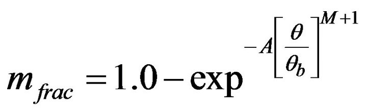 (1)
(1)
where A = coefficient in Wiebe equation = 10.0 for gasoline.
M = coefficient in Wiebe equation = 2.0 for gasoline.
Θ = actual burn angle.
Θb = total burn angle.
2.4. Heat Transfer
Heat transfer was modeled in all elements. Within cylinders the empirically derived heat transfer correlation proposed by Annand [15] was employed.
The connective heat transfer model proposed by Annand is defined as;
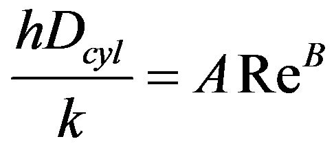 (2)
(2)
where h = heat transfer coefficient [W/m2·K].
A = Annand open or closed cycle coefficient = 0.2.
B = Annand open or closed cycle coefficient = 0.8.
k = thermal conductivity of gas in the cylinder [W/m K].
Dcyl = cylinder bore [mm].
Re = Reynolds number based upon mean piston speed and the engine bore.
Thus the heat transfer per unit area of cylinder wall is defined as:
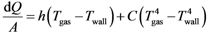 (3)
(3)
where:
 heat transfer per unit area [W/m2].
C = Annand closed cycle coefficient.
2.5. Design Tool
For the purpose of analyzing the engine characteristics the dimensions were considered with Lotus Engineering Software. The engine model is a single-zone model which solves the basic differential equations for intake, compression, power and exhaust strokes. In this analysis, a model of a single cylinders engine has been built and investigated. The fuel used in this study is a gasoline (C8H18). Port injection system has been studied. The compression ratio is 8:1 and kept constant for all engine runs. The EVO was varied from 0˚ - 25˚ and EVC varied from 0˚ - 60˚. The engine speed was varied from 1000 - 5000 rpm. All tests were carried out for equivalence ratio φ = 1. The empirical heat release functions are derived from the Wiebe equation. The engine model uses Annand correlation to estimate engine heat transfer. The engine model also includes a friction model to predict brake power. The engine performance and emissions has been calculated and analyzed. The base engine data are given in Table 1. The engine valve timing is shown in Figure 1. The values of mole fraction of NO, CO were calculated by “ZINOX” program developed by Teodorczyk et al. [16]. In this program, the kinetic model for NO is based on the theory developed by Lavoie et al [17].
3. Results
3.1. Exhaust Valve Opening Angle (EVO)
The calculations were carried out for the engine geometry, fuel, and running conditions shown in Table 1. The original value of (EVO) angle bBDC was varied from 22˚
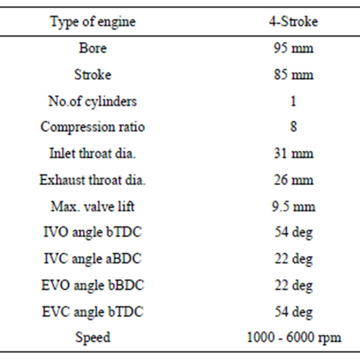
Table 1. Base engine geometry, fuel is gasoline (C8H18).
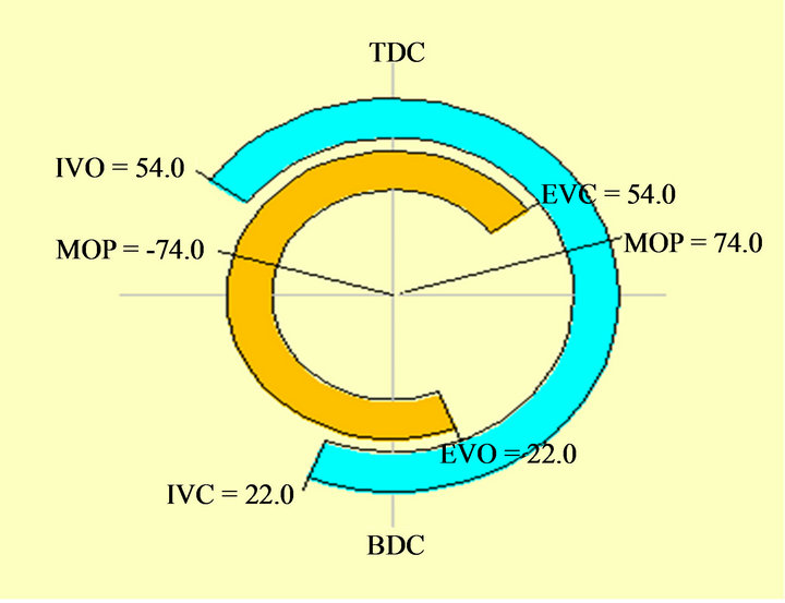
Figure 1. Variable valve timing diagram.
down to 0˚ at BDC in steps; all other parameters were kept constant. The calculations are performed at full load conditions. Figure 2 shows the brake power versus the (EVO) angle opening bBDC for different engine speeds between (1000 - 5000 rpm). It shows a decrease in power with the (EVO) angle reduction for all engine running speeds. But it is less sever at lower engine speed (less than 1500 rpm).That was noticed by Shiga et al. [4], who showed that, at low speeds, a late (EVO) reduce the volumetric efficiency ηvol. In contrast at high engine speeds early (EVO) leads to greater reduction in volumetric efficiency, and this limits the output power. This ηvol reduction was also noticed by Stone [18], where limited maximum power output was noticed. The late opening of the exhaust valve bBDC showed a decrease in BMEP for all engine speeds. In Figure 3, the variation of BMEP versus (EVO) angle bBDC at different engine running speeds between (1000 - 5000 rpm) is shown. This is due to the less effective scavenging of the cylinder, as the pressure decreases, hence the reduced work and BMEP. The effect on BSFC is the opposite as shown in Figure 4. It shows the variation of BSFC versus (EVO) angle that BSFC is highly affected by (EVO) angle at high engine speeds, while it is increased slightly by reducing (EVO) angle at low engine speeds emissions.
3.2. Exhaust Valve Closing Angle (EVC)
For the engine geometry and running conditions shown in Table 1, all parameters were kept constant except the (EVC) angle. It was varied from the original value 54˚ aTDC down to 0˚ at TDC in steps. As shown in Figure 5 the brake power is drawn versus the EVC angle for different engine speeds between (1000 - 5000 rpm). It shows an increase in power with the (EVC) angle reduction but this increase in power was small for values of (EVC) less than 25˚ for all engine running speeds considered. This effect is more recognized at higher engine speeds (2500 -
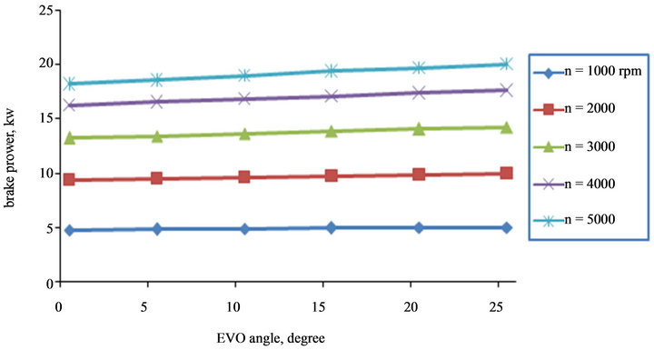
Figure 2. Power versus EVO angle for different speed.
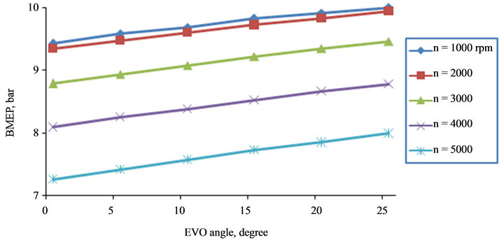
Figure 3. BMEP versus EVO angle for different speed.
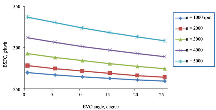
Figure 4. BSFC versus EVO angle for different speed.
5000 rpm). This was also noticed by Shiga et al. [4]. He mentioned that the increase in power may be due to the reduction of residual gases and backflow of exhaust into the inlet manifold, but a late (EVC) closing causes the high pressure exhaust gas reducing the amount of inlet mixture incoming through the inlet manifold. As indicated by Fontana et al. [1] that retarded valve close angles induce a considerable reverse flow and results in the reducetion of ηvol and internal exhaust gas recirculation.
Figure 6 shows the variation of BMEP versus (EVC) angle. The late closing of the exhaust valve showed an increase in BMEP especially at higher engine speeds is noticed. A less effect on BMEP at lower engine speeds. Also this figure shows the insensitivity of BMEP for (EVC) angle at less than 25˚. This was also noticed by Fontana et al. [1] as by decreasing the (EVC) angle the BMEP increases. The BSFC is hardly affected by EVC angle higher than 25˚ for low engine speeds (less than 1500 rpm) as shown in Figure 7, but it was sensitive to (EVC) angle aTDC variation for higher engine speeds. The mechanism is operated by planetary gear train to continuously and precisely change the phase angle between camshaft and crank shaft. The internal ring gear has an external worm tooth so it can acts like a worm wheel. It trains with the worm, the mechanism is operated by planetary gear train to continuously and precisely change the phase angle between camshaft and gear. The four identically planetary gears are meshing with the ring gear and the sun gear and they are carried by the two arms.
3.3. Engine Emissions
Figure 8 shows the effect of (EVO) angle on NO emission at different engine speeds. The reduction of EVO angle causes a further increase of NO mole fraction down to angle 0˚. It is also the case for CO emission mole fraction as shown in Figure 9. The effect of (EVC) angle aTDC on NO emission is shown in Figure 10. The reduction of (EVC) angle causes an increase in NO down to angle 30˚. A further decrease in EVC angle causes a decrease in NO emission. It is also the case for CO emission as shown in Figure 11.

Figure 5. Power versus EVC angle for different speed.
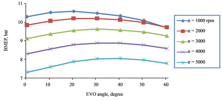
Figure 6. BMEP versus EVC angle for different speed.
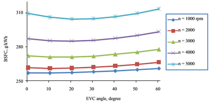
Figure 7. BSFC versus EVC angle for different speed.
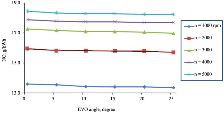
Figure 8. NO versus EVO angle for different speed.
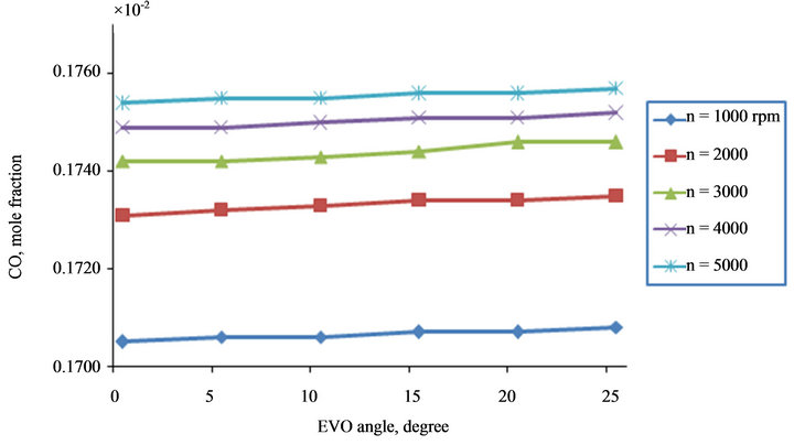
Figure 9. CO versus EVO angle for different speed.
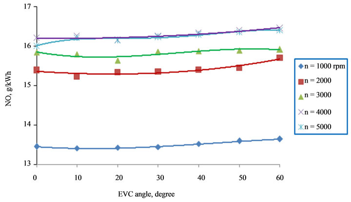
Figure 10. NO versus EVC angle for different speed.
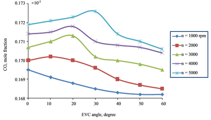
Figure 11. CO versus EVC angle for different speed.
4. Conclusions
1) There is a little effect on engine performance when (EVC) angles reduced to less than 25˚ bTDC at low speeds.
2) There is a reduction in engine performance by decreasing the (EVO) angle bBDC at all engine speeds and an increase of NO emissions.
3) The effect of (EVC) reduction is beneficial to Power, BMEP, and BSFC for different speed and also will reduce engine NO and CO emission down to 20˚ degrees.
4) On the contrary the (EVO) reduction causes a drop in the engine performance and increase NO and CO emission.
REFERENCES
- G. Fontana and E. Galloni, “Variable Valve Timing for Fuel Economy Improvement in a Small Spark-Ignition Engine,” Applied Energy, Vol. 86, No. 1, 2009, pp. 96- 105. doi:10.1016/j.apenergy.2008.04.009
- T. Ahmad and M. Thobald, “A Survey of Variable Valve Actuation Technology,” SAE, New York, SAE Paper 89, 674, 1989.
- O. H. Ghazal, Y. S. Najjar and K. J. Al-Khishali, “Effect of Inlet Valve Variable Timing in the Spark Ignition Engine on Achieving Greener Transport,” World Academy of Science, Engineering and Technology, Vol. 59, 2011, pp. 1073-1077.
- S. Shiga, S. Yagi, M. Morita, T. Matsumoto, T. Krasawa, and T. Nakamura, “Effects on Valve Close Timing for Internal Combustion Engines,” Transactions of the Japan Society of Mechanical Engineers, Vol. 62, No. 596, 1996, pp. 1659-1665.
- H. Hong, G. B. Parvate-Patil and B. Gordon, “Review and Analysis of Variable Valve Timing Strategies—Eight Ways to Approach,” Journal of Automobile Engineering, Vol. 218, No. 10, 2004, pp. 1179-1200. doi:10.1177/095440700421801013
- N. Kosuke, K. Hiroyuki and K. Kazuya, “Valve Timing and Valve Lift Control Mechanism for Engines,” Mechatronics, Vol. 16, No. 2, 2006, pp. 121-129. doi:10.1016/j.mechatronics.2005.09.007
- F. Bozza, A. Gimelli, A. Senatore and A. Caraceni, A Theoretical Comparison of Various VVA Systems for Performance and Emission Improvements of SI-Engines, SAE Paper 2001-010-0670, 2001.
- F. Bonatesta and P. J. Shayler, “Factors Influencing the Burn Rate Characteristics of a Spark Ignition Engine with Variable Valve Timing,” Journal of Automobile Engineering, Vol. 222, No. 11, 2008, pp. 1963-1974. doi:10.1243/09544070JAUTO873
- L. Cao, H. Zhao, X. Jiang and N. Kalian, “Unstanding the Influence of Valve Timings on Controlled Auto-Ignition Combustion in a Four-Stroke Port Fuel Injection Engine,” Journal of Automobile Engineering, Vol. 219, No. 6, 2005, pp. 807-823. doi:10.1243/095440705X11077
- N. Milovanovic, R. Chen and J. Turner, “Influence of Variable Valve Timings on the Gas Exchange Process in a Controlled Auto-Ignition Engine,” Journal of Automobile Engineering, Vol. 218, No. 5, 2004, pp. 567-583. doi:10.1243/095440704774061228
- Y. Ping, X. Zhang, Y. Dong, G. Zhu and Q. Wang, “Study on Performance Improvement of Vehicle Engine by Using Variable Cam Timing,” Neiranji Gongcheng/ Chinese Internal Combustion Engine Engineering, Vol. 29, No. 6, 2008, pp. 20-23.
- T. Rychter and A. Teodorczyk, “Teoria Silnikow Tlokowych,” 1st Edition, WKiL Company, Warszawa, 2006.
- G. Lavoie, J. B. Heywood and C. J. Keck, “Experimental and Theoretical Study of Nitric Oxide Formation in Internal Combustion Engines,” Combustion Science and Technology, Vol. 1, No. 4, 1970, pp. 313-326. doi:10.1080/00102206908952211
- R. Stone, “Introduction to Internal Combustion Engines,” 3rd Edition, McMillan Press, London, 1999.
- Habempirische Formel fur Die Verbrennungsgeschrwindigkeit Verlag der Akademie der Wissenschaften der VdSSR I.Wiebe Moscow (1956)R.
- W. J. D. Annand, “Heat Transfer in the Cylinder of Reciprocating Internal Combustion Engines,” Proceedings of the Institution of Mechanical Engineers, Vol. 177, No. 1, 1963, pp. 973-996.
- W. A. Woods and S. R. Khan, “An Experimental Study of Flow through Poppet Valves,” Proceedings of the Institution of Mechanical Engineers, Vol. 180, No. 14, 1965, pp. 32-41.
- R. S. Benson, “The Thermodynamics and Gas Dynamics of Internal Combustion Engines,” Vol. 1, Clarendon Press, Oxford, 1982.
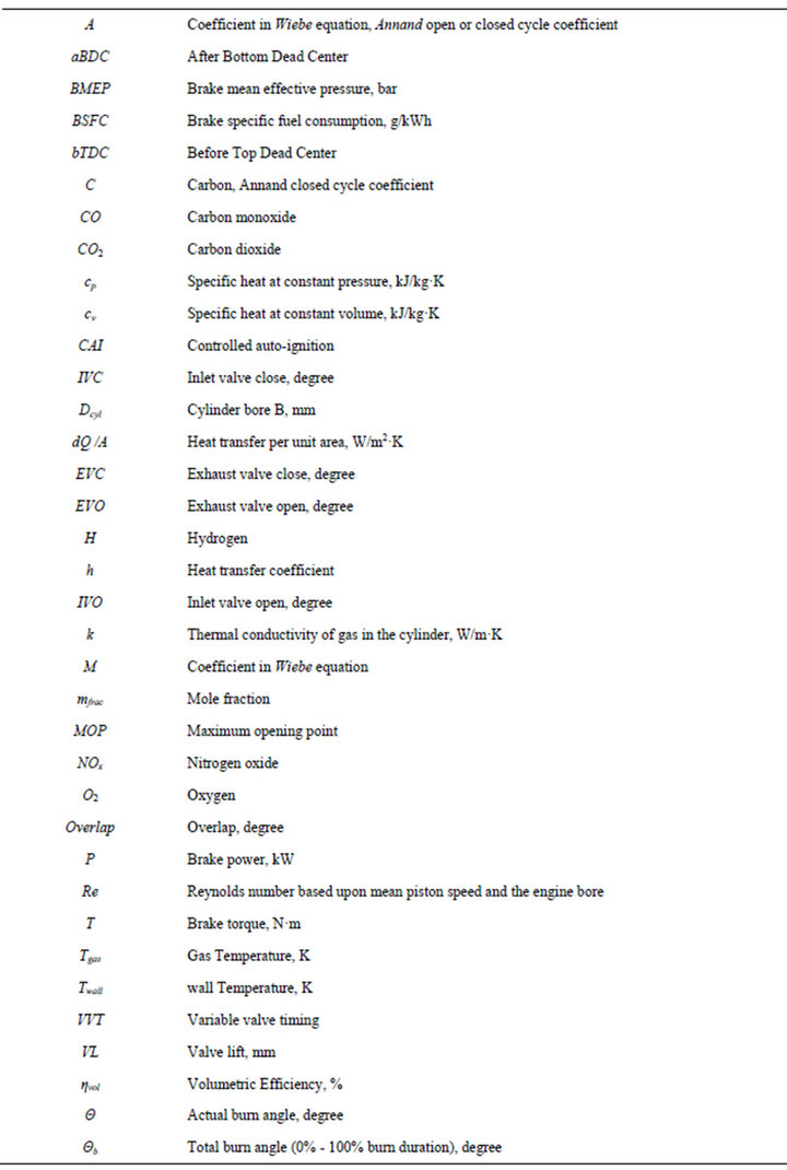
Nomenclature