Journal of Sensor Technology
Vol.4 No.2(2014), Article
ID:44813,11
pages
DOI:10.4236/jst.2014.42005
Design Methodology of a Micro-Scale 2-DOF Energy Harvesting Device for Low Frequency and Wide Bandwidth
Mahmoud M. Magdy1, Ahmed M. R. Fath El-Bab1,2, Samy F. M. Assal1,3
1Mechatronics and Robotics Engineering Department, Egypt-Japan University of Science and Technology, Alexandria, Egypt
2Mechanical Engineering Department, Faculty of Engineering, Assiut University, Assiut, Egypt
3Production Engineering and Mechanical Design Department, Faculty of Engineering, Tanta University, Tanta, Egypt
Email: mahmoud.sharkawy@ejust.edu.eg, ahmed.elbab@eng.au.edu.eg, drengsassal@gmail.com
Copyright © 2014 by authors and Scientific Research Publishing Inc.
This work is licensed under the Creative Commons Attribution International License (CC BY).
http://creativecommons.org/licenses/by/4.0/


Received 2 March 2014; revised 2 April 2014; accepted 9 April 2014
ABSTRACT
A detailed design methodology of a micro-scale 2-DOF energy harvesting device that can harvest human motion energy of low frequency and wide bandwidth is developed. Based on the concept of the 2-DOF vibration absorber, device parameters are selected to harvest energy at low frequency of 1 - 10 Hz and wide bandwidth with ±20% of the mean frequency, which matches the human motion. The device dimensions are limited to 40 × 30 × 10 mm3 to fit with the human wrist size. Then, a finite element model is developed to investigate the system performance with the selected parameters. When subjected to harmonic excitation of 1 g, the proposed 2-DOF device is able to provide a power of at least 10 µW in between the two close resonant peaks of 4 Hz and 6 Hz, which is the target frequency range. The device shows very high power per square frequency compared with the reported harvesters.
Keywords:Energy Harvesting, Two Degree of Freedom, Low Frequency, Wide Bandwidth

1. Introduction
Development of a micro-scale device that can harvest energy from non-traditional source is still very attractive point of research. Such a device is essential for a wide variety of applications such as self-powered wireless sensors and biomedical implants in which energy source is needed. Among the different sources of energy in the environment, vibration/kinetic energy is the most available one, especially where heat and solar energy is not constantly available. Micro-electro mechanical system (MEMS)-based energy harvesting (EH) devices are more compatible with microelectronics applications besides to its low weight and volume [1] .
For vibration-based energy harvesters, there are three types of transduction mechanisms; namely, piezoelectric, electromagnetic and electrostatic [2] . In these mechanisms the efficiency of vibration to electricity conversion is very low in the most existing micro generators, because it suffers from getting the power at narrow bandwidth from the ambient sources due to their single resonance frequency. So, one of the most challenging points for a vibration-based EH device is to obtain the maximum power at low frequency and with wide bandwidth. Generally, EH systems consist of a cantilever beam and a proof mass, so they can be regarded as singleDOF systems. Such systems harvest energy at their first resonant frequency, while their high-order modes are usually neglected because they provide much lower response level compared with the first mode [2] . However, wide bandwidth-based EH devices could be a solution to this problem and many techniques are developed for this purpose. Those techniques can be classified as multi-modal harvesting technique [2] -[9] , resonance tuning technique [10] [11] , and nonlinear technique [12] [13] . A wide variety of multi-modal systems have been developed to obtain a wide bandwidth energy harvester [2] [3] , in which harvesters are based on an array structure from cantilevers with different lengths and tip masses. Different frequencies produced from these cantilevers can cover a wide range of frequency which increases the bandwidth. But such designs suffer from the excess volume and weight. A hybrid energy harvesting device was reported in [4] . In this hybrid system, the harvester consisted of a cantilever beam with bonded piezoelectric plates and a permanent magnet attached at the tip, which oscillated within a stationary coil fixed to the housing. The first and the second resonances of such device were far away from each other (20 Hz and 300 Hz) which provided discrete effective bandwidth. A 2-DOF harvester with a dynamic strain magnifier was proposed in [6] to magnify the power output. It could not achieve two close working frequencies besides that, this magnifier with a spring beam significantly increases the volume and weight of the original harvester. An L-shaped cantilever piezoelectric structure for multimodal energy harvesting was reported [7] . The second natural frequency of this harvester was approximately double the first one. In addition to its large volume, the device design had a problem of voltage cancelation. In [8] , another multi-DOF system that use drotational and translational displacements suffered from the excess volume and thus cannot be realized by MEMS technology. One macro-scale 2-DOF system which overcomes the problem of the excess volume by designing the so-called “cutout” beam was developed in [9] . Compared with the previously reported 2-DOF harvester designs, it was more compact and could have two close resonant frequencies.
In this paper, in order to obtain high power with wide bandwidth in a pre-specified volume; a detailed design methodology of a 2-DOF EH system is developed based on the cutout beam design, targeting the low frequency range of the human motion. Based on the most dominant frequency for the human motion during the daily activities, the system parameters are selected. Then, a finite element model is developed to investigate the system performance with the selected design parameters. Finally, the open circuit voltage is calculated based on piezoelectric transaction mechanism. This paper is organized as follows: Section 2 introduces the 2-DOF EH system model. Then based on system model, Section 3 presents the selection criteria of the system parameters. Section 4 shows the finite element model of the system with the selected parameters to investigate its performance with low frequency. Finally, the discussion and conclusions are presented in Section 5.
2. Energy Harvester Design
2.1. Energy Harvester Mathematical Model
Because one of our targets is to develop an EH with wide bandwidth, a 2-DOF harvester is selected here. The 2-DOF vibration system-based EH, as shown in Figure 1(a) consists of two masses and twosprings; namely, the firstmass (m1) and the second mass (m2), the first spring (k1) and the second spring (k2). The wide bandwidth of this 2-DOF system is attributed to the frequency range between the two amplitude peaks at resonances compared to that of the one peak for the single-DOF system. The dynamic model of this system under the base excitation force of  is given as follows:
 (1)
(1)
where  and ω are the amplitude and frequency of the exciting force, respectively. x1 and x2 are the displacements of m1 and m2, respectively. The amplitudes X1 and X2 can be expressed as:
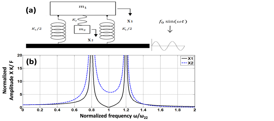
Figure 1. (a) Schematic diagram of a vibration absorber; (b) Normalized amplitudes vs. normalized frequency.
 (2)
(2)
 (3)
(3)
It is evident from Equation (2) that the amplitude  of the main system mass becomes zero when the exciting frequency
  reaches the value of
 . At this condition, the amplitude of the second mass becomes
  as shown in Figure 1(b). This is the well-known condition for the second spring-mass system to work as a vibration absorber suppressing the displacement of the first mass. This condition plays a critical role in the design, as it will be explained later.
The maximum energy, which can be gained from the 2-DOF harvester system, is the amount of the dissipated energy by the absorber damping c2. Therefore, the output power (P) depends on the difference between the amplitudes of the two masses and the damping value (c2) as follows [14] :
 (4)
(4)
where c2 is the equivalent damping ratio due to transaction from mechanical to electrical energy. Satisfying the above condition achieves the following merits:
1) A large amplitude difference between the two masses over the targeted frequency range, which increases the resultant output power (It will be shown later in Subsection 3.1).
2) The continuity of the output signal due to existence of two close resonance peaks in the targeted bandwidth without scarfing the power density (power/volume).
3) Keeping the first mass almost stationary at the most dominant frequency of the human motion during the daily activities. In case of using the piezoelectric material as transduction mechanism, this will avoid the voltage signal cancellation, due to the generation of a positive charge at the first spring K1 and the a negative charge at the second spring K2, when X1 and X2 are out of phase.
So, the system parameters (m1, m2, k1, k2) are selected to satisfy this condition. Also, low frequency (human motion) and wide bandwidth should be considered. This selection process will be discussed in Section 3.
2.2. Energy Harvester Design Layout
The proposed device is designed as “cutout” beam as shown in Figure 2. It consists of two beams to act as the two springs K1 and K2 and two masses m1 and m2 which are located at the end of the two beams. Each proof

Figure 2. Layout of the proposed EH system.
mass is placed at the end of each beam to act as a concentrated load. In the meantime, the second beam K2 with small thickness and wide widthis configured to get low value ofspring stiffness and provide a large area of stress. The proposed layout, cutout beam design, is more compact than the conventional 2-DOF harvesters, because this design comprises one main cantilever and an inner secondarycantilever which reduces the total volume of the harvester.
3. System Design Procedure
In this section, based on the human motion with low frequency and target bandwidth, the system parameters (m1, m2, k1, k2) will be selected. The selection procedure is based on the following criteria:
1) The resonant frequency of the device is selected to match the human motion frequency range.
2) The frequency bandwidth of the device should be matched with the human frequency spectrum.
3) The output generated power should be as large as possible.
4) The EH device size is selected to be 40 × 30 × 10 mm3 to fit the human wrist size.
3.1. Frequency Range Selection
Firstly, the frequency range of the human motion ranges from 1 to 10 Hz based on the reported values in [15] . So, the most dominant frequency (the mean frequency) is selected as  = 5 Hz = 30 rad/s. Secondly, the power generated from the proposed harvester can be determined using Equation (4). It can be noted from Equation (4) that, the higher the difference between the two amplitudes
 , the higher the generated power. On the other hand, the higher the ratio of the bandwidth, the lower the difference between the two amplitudes
  as shown in Figure 3, and the lower the power generated. The amplitudes difference
  with band width ratio of ±20%, is shown in Figure 4.
In other words, there is a tradeoff between the generated power and the bandwidth regarding the amplitude difference. So, to compromise between wide bandwidth and power generated, three cases of bandwidth ratios are studied; namely, bandwidth of ±10%, ±20%, and ±30% of the mean frequency, as shown in Figure 3(a), Figure 3(b), Figure 3(c), respectively. The case of ±20% bandwidth ratio is selected here to match the frequency range of the human motion during the day activities which is about ±18% [15] . As a summary, the mean frequency and the bandwidth are selected as 5 Hz and ±20% respectively.
3.2. System Parameters Calculation
Based on the third criteria, in order to maximize the generated power, the stress in the piezoelectric layer should be maximized. So, according to the maximum allowable stress of the piezoelectric material (25 MPa) [16] , the required mass m2, which affect the stress induced in second beam K2 and subsequently on the stress of piezoelectric layer, as shown in Figure 5, is calculated. The stress σ induced in the second beam K2 can be calculated as:
 (5)
(5)
where  which is equivalent to
  is effective force in which
  is the exciting acceleration equals to 1g,which is the most dominant acceleration of the human motion [15] .
  is the second beam length.
  in which
  is the thickness of the second beam.
  is the moment of inertia in which
  is the width of the second beam. E is the Young’s modulus and d is the allowable deflection. From
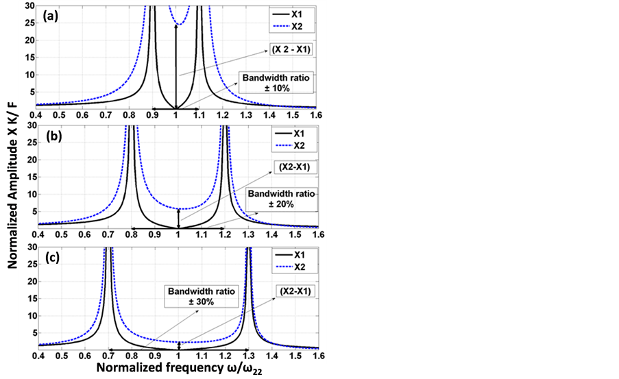
Figure 3. Normalized amplitudes vs. normalized frequency with different bandwidth ratio.
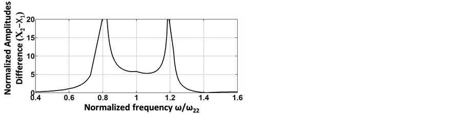
Figure 4. Normalized amplitudes difference vs. normalized frequency at bandwidth ratio ±20%.
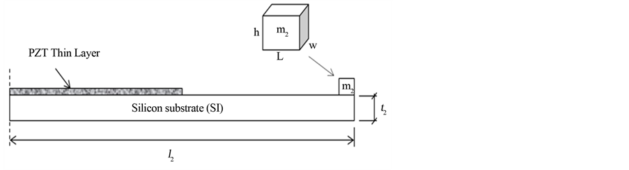
Figure 5. Schematic drawing of secondary beam.
Equation (5), the relation between the stress and the thickness can be obtained as follows:
 (6)
(6)
Substituting Equation (6) into Equation (5), the stress can be obtained as follows:
 (7)
(7)
From Equation (7), the thickness of second beam can be calculated as follows:
 (8)
(8)
Also, from Equation (5) the stress can be formulated as:
 (9)
(9)
where E of Silicon (Si) is 160 GPa. Using the specified device size, the length  and width
  of the second beam are 30 mm and 25 mm, respectively. Also, the allowable deflection d is taken equal to half of the device height, d = 5 mm. Finally using Equations (8) and (9),
  can be calculated as
  = 0.15 gm.
The masses  are chosen as a Tungsten material due to its high density of 19,300 kg/
 . The width of
  is taken equal to the width of the beam and its height is h = 500 µm, which is the thickness of Tungsten wafer. Then, the length of
  is calculated as 0.5 mm. Finally, according to the condition
 , k2 can be calculated as
 .
.
From the characteristic equations of the 2-DOF EH system shown in Figure 1(a), the relationship between the two resonance frequencies and the system parameters (m1, m2, k1, k2) can be obtained as follows [17] :
 (10)
(10)
 (11)
(11)
The two resonance frequencies are taken as ±20% of  30 rad/s; namely,
  = 24 rad/s and
  = 36 rad/s. Then, m1 and k1 can be calculated from Equations (10) and (11) to achieve the desired resonance frequencies of the system as
  and
and .
.
4. Finite Element Analysis
In this section, ANSYS software is used for creating a virtual testing setup for the proposed EH devices with the selected parameters. The springs k1 and k2 of the EH device are modeled as Silicon material (Young’s modulus of 160 GPa and Poisson ratio ν = 0.23) .The masses are modeled as Tungsten (Young’s Modulus of 411 GPa and Poisson ratio ν = 0.28). The dimensions of the EH device are shown in Figure 6 and listed in Table1 Then, the boundary conditions are taken as:
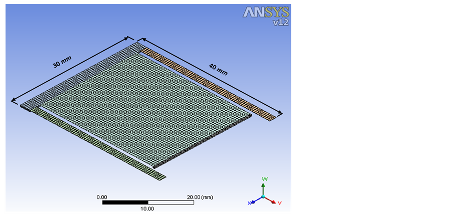
Figure 6. Meshing of EH system.

Table 1. Dimensions of energy harvesting device.
1) Exciting frequency range is from 1 to 10 Hz.
2) Exciting acceleration for the EH system is 1 g.
3) The end of the second beam k2 is considered as a fixed end.
4) The system is meshed into solid tetrahedral elements with a medium divided mesh as shown in Figure 6.
Two analyses are performed to validate the device performance. The first includes a modal frequency analysis to determine the modal shapes of the EH system. The second is a harmonic response analysis to determine the displacement of mass m2 and the stress induced in k2.
4.1. Modal Analysis
This subsection focuses on the determination of the natural frequencies and modal shapes of the EH system during the excitation of the system. Modal analysis is performed using ANSYS software in order to find the natural frequencies and corresponding modal shapes of EH system. The first and the second mode shapes are shown in Figure 7, while the natural frequencies of the first three modes are summarized in Table2 The first mode shape shown in Figure 7(a) is the normal mode during which the secondary beam vibrates perpendicular to the plane of the system. In the second mode shape shown in Figure 7(b), the secondary beam appears to rotate about an axis parallel to the plane of the system.
According to the values shown in Table 2, the harvester tends to oscillate in the first mode when excited and the frequency of this first mode is within the target frequency range required for applications of human motion. The motion of this mode generates maximum stress at the root of k2 which induces electric charge in the piezoelectric layer as shown on Figure 8.
4.2. Harmonic Response Analysis
In this subsection, a simulation of the harmonic system response using ANSYS software is carried out. The displacements of m2 at different exciting accelerations (0.5 g, 0.7 g, 1 g) are shown in Figure 9. This figure shows that the proposed device can harvest energy with wide bandwidth and at frequencies that match the human motion. This is due to the proper selection of the system parameters as discussed before. This figure shows also that thevariation of exciting acceleration has small effect on the displacement of m2 in between the two peaks. This means that relatively stable output power can be obtained within the target frequency range, when thehuman acceleration changes during motion.
Table 2. Theortical values of the first three natural frequencies.
 (a)
(a)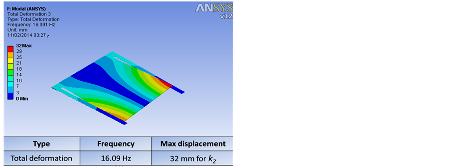 (b)
(b)
Figure 7. The First two modal shapes by ANSYS simulation (a) The first mode (b) The second mode.
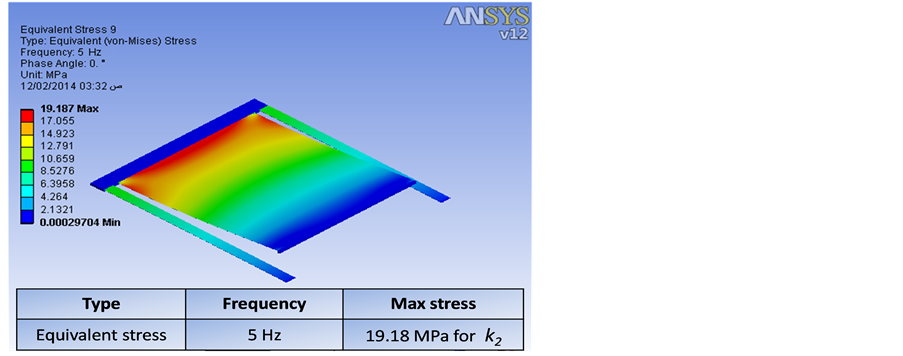
Figure 8. Stress distribution of EH system.
4.3. Stress Analysis and Voltage Generation
In this subsection, a piezoelectric layer (PZT) is assumed to be deposited on the second beam with thickness tp = 10 µm as shown in Figure 10 to convert the mechanical stress to voltage. This piezoelectric layer operates in 3-1 mode, which means that the mechanical stress/strain is applied in the axialdirection (1-direction) while the electrical field is generated in transverse direction (3-direction) as shown in Figure 10. Hence, based on the equation of the open-circuit, the voltage  that generated across the piezoelectric electrodes can be obtained from Equation (12) [18] . Table 3 shows the material properties of PZT layer.
 (12)
(12)
The theoretical value of output voltage can be calculated from the simulation software based on the stress
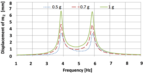
Figure 9. Displacement of m2 vs. Frequency.
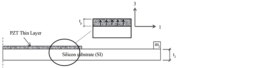
Figure 10. Mode 3-1 of piezoelectric layer.
Table 3. Material properties of piezoelectric trancducer.
distribution over the frequency range from 1 - 10 Hz in the secondary beam. The value of the voltage has two peaks of 4.7 V and 4.5 V at the two resonance frequencies of the system as shown in Figure 11.
4.4. Power Calculation
Using Equation (4) the power generated by the system can be calculated by assuming the total damping ratio as c2 = 0.1. Figure 12 shows the generated power with respect to the normalized frequency and acceleration. The generated power of the system at the center frequency of 5 Hz and excitation acceleration of 1 g is 20 µW. The actual useful power harvested by the system is affected by the mechanical to electrical efficiency for piezoelectric transducer which is taken as (50%) [19] . So, the useful harvested power can be calculated as 10 µW.
5. Discussion and Conclusions
A detailed design procedure of a 2-DOF piezoelectric EH system is presented here to harvest the human motion energy at frequency range from 1 Hz to 10 Hz. The system design parameters are selected to satisfy the condition of a vibration absorber and constrained by volume of (40 × 30 × 10) mm3. This helps to get wide bandwidth and high output power. A finite element model is developed to investigate the system performance. The displacement of the secondary mass m2 shows wide bandwidth of (4 - 6 HZ) with different exciting accelerations (0.5 g, 0.7 g, 1 g), which matches the human motion frequency range. The generated useful power of the system at a total damping ratio of 0.1 and exciting acceleration of 1 g is 10 µW at the center frequency 5 Hz.
The output power and the frequency range of the proposed EH system are compared with the other reported
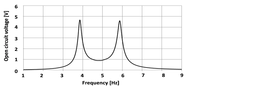
Figure 11. Open circuit output voltage vs. frequency.
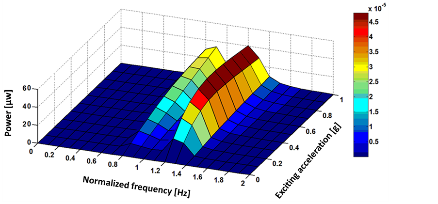
Figure 12. The harvested power at different exciting acceleration and normalized frequency.
Table 4. Comparison between this proposed system and other published wide banwidth EH systems.
F-BW: Frequency Bandwidth; C-F: Center Frequency; P-SCF: Power per Square of Central Frequency.
EH multi-modal systems as shown in Table4 Because the generated power is proportional to the square of the operating frequency, as given by Equation (4), the power per square of central frequency (P-SCF) is used in this comparison. The power per square of central frequency value (P-SCF) is calculated as the output power at the central frequency divided by the square of central frequency value. The proposed EH system shows high P-SCF compared with the other reported EH system. Finally, the system fabrication and the experimental testing are the future extensions of this work.
Acknowledgements
The first author is supported by a scholarship from the Mission Department, Ministry of Higher Education of the Government of Egypt which is gratefully acknowledged.
References
- Beeby, S.P., Tudor, M.J. and White, N.M. (2006) Energy Harvesting Vibration Sources for Microsystems Applications. Measurement Science and Technology, 17, 175-195.http://dx.doi.org/10.1088/0957-0233/17/12/R01
- Shahruz, S. (2006) Design of Mechanical Band-Pass Filters for Energy Scavenging. Journal of Sound and Vibration, 292, 987-998. http://dx.doi.org/10.1016/j.jsv.2005.08.018
- Ferrari, M., Ferrari, V., Guizzetti, M., Marioli, D. and Taroni, A. (2008) Piezoelectric Multifrequency Energy Converter for Power Harvesting in Autonomous Microsystems. Sensors and Actuators A: Physical, 142, 329-335. http://dx.doi.org/10.1016/j.sna.2007.07.004
- Tadesse, Y., Zhang, S. and Priya, S. (2009) Multimodal Energy Harvesting System: Piezoelectric and Electromagnetic. Journal of Intelligent Material Systems and Structures, 20, 625-632.http://dx.doi.org/10.1177/1045389X08099965
- Ou, Q., Chen, X., Gutschmidt, S., Wood, A. and Leigh, N. (2010) A Two-Mass Cantilever Beam Model for Vibration Energy Harvesting Applications. International Conference on Automation Science and Engineering (CASE 2010), Toronto, 21-24 August 2010, 301-306.
- Arafa, M., Akl, W., Aladwani, A., Aldrarihem, O. and Baz, A. (2011) Experimental Implementation of a Cantilevered Piezoelectric Energy Harvester with a Dynamic Magnifier. In: SPIE Smart Structures and Materials+ Nondestructive Evaluation and Health Monitoring, International Society for Optics and Photonics, 79770Q-79770Q.
- Erturk, A., Renno, J.M. and Inman, D.J. (2009) Modeling of Piezoelectric Energy Harvesting from an L-Shaped Beam-Mass Structure with an Application to UAVs. Journal of Intelligent Material Systems and Structures, 20, 529-544. http://dx.doi.org/10.1177/1045389X08098096
- Kim, I.-H., Jung, H.-J., Lee, B.M. and Jang, S.-J. (2011) Broadband Energy-Harvesting Using a Two Degree-of-Freedom Vibrating Body. Applied Physics Letters, 98, Article ID: 214102. http://dx.doi.org/10.1063/1.3595278
- Wu, H., Tang, L.H., Yang, Y.W. and Soh, C.K. (2013) A Novel Two-Degrees-of-Freedom Piezoelectric Energy Harvester. Journal of Intelligent Material Systems and Structures, 24, 357-368.http://dx.doi.org/10.1177/1045389X12457254
- Roundy, S. and Zhang, Y. (2005) Toward Self-Tuning Adaptive Vibration-Based Micro Generators. Proceedings of SPIE, 5649, 373-384. http://dx.doi.org/10.1117/12.581887
- Leland, E.S. and Wright, P.K. (2006) Resonance Tuning of Piezoelectric Vibration Energy Scavenging Generators Using Compressive Axial Preload. Smart Materials and Structures, 15, 1413-1420.http://dx.doi.org/10.1088/0964-1726/15/5/030
- Erturk, A., Hoffmann, J. and Inman, D.J. (2009) A Piezomagnetoelastic Structure for Broadband Vibration Energy Harvesting. Applied Physics Letters, 94, Article ID: 254102. http://dx.doi.org/10.1063/1.3159815
- Arrieta, A.F., Hagedorn, P., Erturk, A. and Inman, D.J. (2010) A Piezoelectric Bistable Plate for Nonlinear Broadband Energy Harvesting. Applied Physics Letters, 97, Article ID: 104102.http://dx.doi.org/10.1063/1.3487780
- Tang, X.D. and Zuo, L. (2011) Enhanced Vibration Energy Harvesting Using Dual-Mass Systems. Journal of Sound and Vibration, 330, 5199-5209.http://dx.doi.org/10.1016/j.jsv.2011.05.019
- Yun, J., Patel, S.N., Reynolds, M.S. and Abowd, G.D. (2011) Design and Performance of an Optimal Inertial Power Harvester for Human-Powered Devices. Mobile Computing, IEEE Transactions, 10, 669-683.http://dx.doi.org/10.1109/TMC.2010.202
- Dompierre, A., Vengallatore, S. and Frechette, L.G. (2011) Theoretical and Practical Limits of Power Density for Piezoelectric Vibration Energy Harvesters. The 11th International Workshop on Micro and Nanotechnology for Power Generation and Energy Conversion Applications (PowerMEMS 2011), 249-252.
- Thomson, W. (1996) Theory of Vibration with Applications. CRC Press, Boca Raton.
- Liu, H.C., Tay, C.J., Quan, C.G., Kobayashi, T. and Lee, C.K. (2011) Piezoelectric MEMS Energy Harvester for LowFrequency Vibrations with Wideband Operation Range and Steadily Increased Output Power. Microelectromechanical Systems Journal, 20, 1131-1142.
- González, J.L., Rubio, A. and Moll, F. (2002) Human Powered Piezoelectric Batteries to Supply Power to Wearable Electronic Devices. International Journal of the Society of Materials Engineering for Resources, 10, 34-40.